Design of a Robot for Gait Rehabilitation by
Caitlyn Joyce Bosecker B.S., Mechanical Engineering (2006) Northeastern University
ARCHIVES
MASSACHUSETTS INS E OF TECHNOLOGYMAY 0
1
2009
LIBRARIES
Submitted to the Department of Mechanical Engineering in Partial Fulfillment of the Requirements for the Degree of Master of Science in Mechanical Engineering
at the
Massachusetts Institute of Technology February 2009
C 2009 Massachusetts Institute of Technology All rights reserved
Signature of Author...
Departnint of Mecha nical Engineering January 16, 2008 N"
N'
C ertified by ...
ano'fgo Krebs Principle Research Sui tist and Lecturer Thesis Supervisor
A ccepted by ...
David'E. Hardt Professor and Graduate Officer Department of Mechanical Engineering
Design of a Robot for Gait Rehabilitation by
Caitlyn Joyce Bosecker
Submitted to the Department of Mechanical Engineering
on January 16, 2009 in Partial Fulfillment of the Requirements for the Degree of Master of Science in Mechanical Engineering
Abstract
The ability to walk is important for independent living and when this capacity is affected by injury, gait therapy is the traditional approach to re-train the nervous system, to re-build muscle strength, to improve balance, and to re-train kinematics in order to reduce the stresses applied to bones and muscles. The importance of this problem is illustrated by the approximately 5.8
million stroke survivors alive in the US today and an estimated 700,000 strokes occurring each year. In fact, for stroke survivors with mild to moderate impairment, only 37% regain the ability to walk within one week post-stroke and 73% fall within the first six months. Falls are a leading cause of injury among Americans over 65 years old with over one third of this population experiencing a fall each year and an unsteady gait increases this risk. This growing population will require gait therapy.
This thesis presents the design, development, fabrication, and proof-of-concept testing for a novel device to deliver gait therapy. While robotic devices exist, none of them take advantage of the concept of passive walkers and most focus on reproducing gait kinematics for impaired patients. Yet research has found that appropriate neural input is an important factor in efficacious therapy. For gait, this input would be the collision between the foot and the ground at heel-strike. The goal of this novel device is to allow patients to begin gait therapy before they are able to independently walk overground while maximizing the amount interface driven neural input during stepping in a safe environment.
Thesis Supervisor: Hermano Igo Krebs
Table of Contents
h Chapter 1: Introduction... 8 1.1 M otivation... 8 1.2 Thesis Overview ... 8 2 Chapter 2: Background ... 102.1 Stroke and Spinal Cord Injury ... 10
2.2 Gait Basics ... 11
2.2.1 Gait K inem atics ... 12
2.2.2 Pathological Gait... 14
2.3 Central Pattern Generator ... 19
2.4 Gait Therapy ... 20
2.4.1 Physiotherapy... 21
2.4.2 Robotic Therapy ... 22
3 Chapter 3: D esign Concepts and Selection... 30
3.1 TRIZ - Theory of Inventive Problem Solving... 31
3.2 K 'nex Proof-of-Concept ... 32
3.3 Functional Requirem ents ... 33
3.3.1 Treadm ill... 36
3.3.2 Body W eight Support ... 39
3.4 A ctuation D esign ... 40
3.4.1 Lead and Ball Screw s... 40
3.4.2 Lever ... 42
3.4.3 Cam ... 43
3.4.4 Hydraulic A ctuator w ith Return Spring... 44
3.4.5 Hydraulic Bi-D irectional A ctuator ... 46
3.4.6 Pneum atic Bi-Directional A ctuator... 46
3.4.7 Linear A ctuator ... 47
3.5 Cam vs. Hydraulic A ctuation... 48
3.5.1 Cam D esign Requirem ents ... 48
3.5.2 Hydraulic System Requirem ents... 50
3.6 Body W eight Support System ... 55
4 Chapter 4: D etailed D esign and D evice A ssem bly... 58
4.1 Cam Design... 58
4.1.1 Cam Profile Developm ent... 59
4.1.2 Pressure Angle ... 68
4.1.3 Cam Surface Coordinates ... 70
4.2 Cam shaft M aterial Selection... 73
4.3 Cam shaft Bearing Selection... 75
4.3.1 Ball Bearings... 75
4.3.2 Angular Contact Bearings ... 76
4.3.3 Cylindrical Roller Bearings ... 76
4.3.4 N eedle Roller Bearings... 77
4.3.5 Tapered Roller Bearings ... 77
4.4 Full Cam System ... 79
4.6 Body W eight Support (BW S) D esign... 82
4.6.1 BW S Fram e... 82
4.6.2 BW S Subject Interface... 86
5 Chapter 5: Device Troubleshooting and Healthy Subject Testing... 92
5.1 M otor G ear Reduction ... 92
5.2 Treadm ill Speed Reduction... 94
5.3 Fully A ssem bled System ... 96
5.4 H ealthy Subject Testing... 98
5.4.1 Electrom yography... 98
5.4.2 H ealthy Subject Test Results ... 101
5.4.3 M annequin Testing ... 108 6 Chapter 6: Conclusions... 112 6.1 Project Evaluation... 112 6.2 Future W ork... 112 References... 115 Appendix A ... 119
Appendix B: Kinematic Robot-Based Evaluation Scales and Clinical Counterparts to Measure Upper Limb Motor Performance in Patients with Chronic Stroke ... 128
B I Introduction... 128
B2 M ethods ... 129
B3 Results ... 134
B4 D iscussion ... 138
B5 Investigating Shoulder/Elbow Score of the Fugl-Meyer Assessment... 140
B6 Principle Com ponent A nalysis... 142
Appendix B References ... 145
Appendix C: MRI-Compatible Wrist Robot: Seal Redesign and Phantom Testing... 148
Cl Internal Leakage n ... 148
C2 Seal edesin ... 151
C3 Leakage and Friction Testing ... 154
C4 Phantom Testing ... 158
C5 Conclusions ... 162
List of Figures
Figure 2-1. Spinal cord levels and corresponding function. ... 11
Figure 2-2. Normal human gait cycle at about 3 ft/sec (1 m/sec) [5]... 12
Figure 2-3. Anatomical planes of the human body (axial also known as the frontal plane). ... 12
Figure 2-4. Trajectory of hip movement during gait. ... 13
Figure 2-5. Trajectory of hip and knee during gait (side view)... 13
Figure 2-6. Anterior trunk bending... 15
Figure 2-7. Posterior trunk bending... 16
Figure 2-8. C ircum duction... 16
Figure 2-9. H ip hiking... 17
Figure 2-10. Steppage... 18
Figure 2-11. V aulting... 18
Figure 2-12. Golgi tendon organ... 20
Figure 2-13. LiteGait, a) coupled with a treadmill, b) for overground training. ... 24
Figure 2-14. G ait Trainer I... 25
Figure 2-15. H aptic W alker. ... 26
Figure 2-16. KineAssistTM...27
Figure 2-17. L okom at@ . ... 28
Figure 3-1. Two-legged passive walker [34]... 30
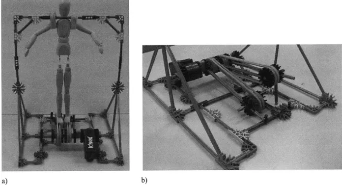
Figure 3-2. K'nex scaled proof-of-concept, a) system with 12" mannequin, b) close-up of treadm ill concept... 33
Figure 3-3. Anthropometrics a) 99% Male, b) 1% Female [37]... 35
Figure 3-4. Foot clearance and time requirements for treadmill actuation... 36
Figure 3-5. Angles during a healthy gait cycle at about 3.3 ft/sec of, a) the hip, b) knee, and c) an k le... 3 7 Figure 3-6. a) BowFlex@ TreadClimber@, b) TreadClimber@ in Use. ... 38
Figure 3-7. Lead screw example... 40
Figure 3-8. B all screw ... 4 1 Figure 3-9. Lead screw design configuration. ... 41
Figure 3-10. Lead screw jamming under a moment load. ... 41
Figure 3-11. Lead screw configuration to reduce overturning load... 42
Figure 3-12. Mechanical advantage of a lever... 42
Figure 3-13. Lever design concept... 43
Figure 3-14. Cam design concept, a) cam design side view, b) front view... 44
Figure 3-15. Hydraulic actuator with return spring. ... 45
Figure 3-16. Bi-directional hydraulic actuator... 46
Figure 3-17. Bi-directional pneumatic actuator... 46
Figure 3-18. Linear actuators... 47
Figure 3-19. Determining required camshaft speed from stride length ... 48
Figure 3-20. Motor torque/speed curve. ... 50
Figure 3-21. Device to test the mechanics of running under simulated low gravity [41]... 56
Figure 3-22. Honda leg assist device... 56
Figure 4-1. a) Radial Cam, b) Axial Cam [39]. ... 58
Figure 4-2. Timing Diagram for Both Treadmills. ... 60
Figure 4-3. Naive cam SVAJ diagram [39]. ... 60
Figure 4-4. Double-Dwell cycloidal position SVAJ diagram... 62
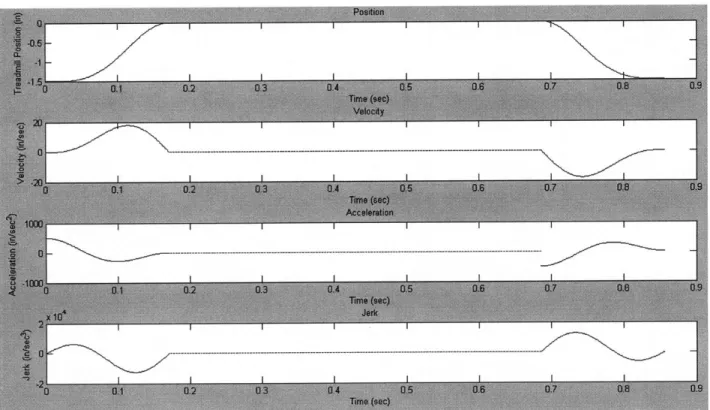
Figure 4-5. Single-Dwell cycloidal position SVAJ diagram. ... 63
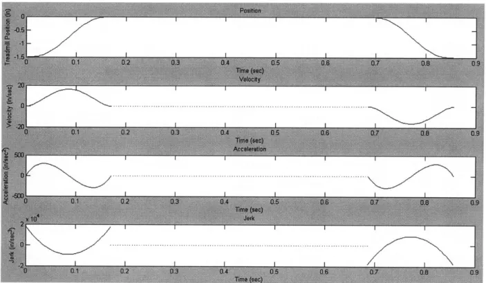
Figure 4-6. Single-Dwell double harmonic SVAJ diagram... 65
Figure 4-7. Single-Dwell polynomial SVAJ diagram... 67
Figure 4-8. Cycloidal, double harmonic, and polynomial position functions. ... 67
Figure 4-9. Prime radius for a cam roller follower [39]. ... 68
Figure 4-10. Pressure angle of an oscillating roller follower [39]... 69
Figure 4-11. Pressure angle for a cam with Rp = 5.75 inches... 70
Figure 4-12. Cam profile of an oscillating roller follower [39]... 71
Figure 4-13. Cam surface coordinates... 72
Figure 4-14. Loading of camshaft... 73
Figure 4-15. a) Conrad ball bearing, b) filling slot ball bearing [46]. ... 75
Figure 4-16. Angular contact bearing ... 76
Figure 4-17. Cylindrical roller bearing [46]. ... 77
Figure 4-18. Needle roller bearing [46]... 77
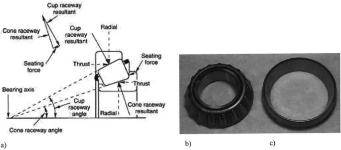
Figure 4-19. a) cone geometry of tapered roller bearing, b) tapered roller bearing cone, c) cup. 78 Figure 4-20. Method for preloading tapered roller bearings [47]... 78
Figure 4-21. Cam system for treadmill actuation. ... 79
Figure 4-22. Detail of bearing pre-load design... 80
Figure 4-23. Assembled cam subsystem... 80
Figure 4-24. Treadmill height modification... 81
Figure 4-25. Treadmill motor height modification ... 81
Figure 4-26. 80/20, 3030 aluminum extrusion, a) front view and dimensions, b) isometric view [4 8]... 82
Figure 4-27. BWS frame, a) front view, b) side view, c) isometric view... 83
Figure 4-28. BWS frame base member bending, a) location of beam in frame, b) force diagram. ... 8 4 Figure 4-29. BWS subject interface attachment member bending, a) location of beam in frame, b) force diagram ... 84
Figure 4-30. BWS frame cross member bending, a) location of beam in frame, b) force diagram. ... 8 5 Figure 4-31. BWS frame column buckling, a) location of beam in frame, b) force diagram... 85
Figure 4-32. a) body weight support subject interface, b) subject harness... 86
Figure 4-33. a) loading on bicycle seat, b) diagram of cantilever bending. ... 87
Figure 4-34. Added BWS vertical stability, a) side view, b) detailed view. ... 88
Figure 4-35. Vertical DOF in bicycle seat, a) bicycle seat, b) cross-sectional view of nesting p ip es... 8 8 Figure 4-36. Vertical DOF in upper body support, a) upper body support, b) cross-sectional view of nesting pipes. ... 89
Figure 4-37. BWS pelvic rotation degree of freedom... 90
Figure 4-38. Back support, a) front view, b) vertical back support, and c) back support at 200.. 90
Figure 5-1. 20:1 ratio gear reducer. ... 93
Figure 5-2. Camshaft gear reduction, a) side view, b) top view... 94
Figure 5-3. Schematic of pulley reduction and belt length ... 95
Figure 5-4. Treadmill pulley, a) original 4.3:1 reduction, b) modified 6:1 reduction ... 96
Figure 5-6. Fully assembled system, a) front view, b) side view. ... 97
Figure 5-7. Tibialis anterior [52]. ... 99
Figure 5-8. Soleus [52]. ... 99
Figure 5-9. R ectus fem oris [52]... 100
Figure 5-10. Sem itendinosus [52]... 101
Figure 5-11. Subject EMG placement. ... 101
Figure 5-12. Muscle activity during one gait cycle [51]... 102
Figure 5-13. Average healthy subject walking EMG data [51]... 102
Figure 5-14. Healthy subject normal treadmill walking TA EMG... 103
Figure 5-15. Healthy subject normal treadmill walking soleus EMG. ... 104
Figure 5-16. Healthy subject normal treadmill walking rectus femoris EMG. ... 104
Figure 5-17. Healthy subject normal treadmill walking semitendinosus EMG... 105
Figure 5-18. Healthy subject actuated treadmill walking TA EMG... 106
Figure 5-19. Healthy subject actuated treadmill soleus EMG. ... 107
Figure 5-20. Healthy subject actuated treadmill rectus femoris. ... 107
Figure 5-21. Healthy subject actuated treadmill walking semitendinosus EMG... 108
Figure 5-22. Mannequin test, a) at toe-off, b) swing phase, c) heel-strike. ... 109
Figure 5-23. Mannequin goniometer placement... 109
Figure 5-24. Mannequin hip angle... 110
Figure 5-25. Mannequin knee angle. ... 110
List of Tables
Table 3-1. Subject anthropometrics [37]. ... 34Table 3-2. Motor torque and speed characteristics. ... 50
Table 4-1. Boundary Conditions for Single-Dwell Polynomial Functions... 66
Acknowledgements
I would like to thank my advisor, Dr. Igo Krebs, for allowing me to pursue three different research projects which I enjoyed while learning a great amount from the experience.
Current and former members of the Newman Lab have been willing to answer my questions on many topics, attempted to pass on expertise, and made Journal Club a fun and rewarding experience. In no particular order I would like to thank: Steven Charles, Jooeun Ahn, Yun Seong Song, Shelly Levy-Tzedek, Benedetta Cesqui, Laura Dipietro, Emilio Gonzalez, Domenico Formica, Patrick Ho, Hyunglae Lee, Mohammad Rastgaar, and Nevan Hanumara.
I would not have been able to complete the machining for my projects without the help and advice from Mark Belanger in the Edgerton Student Shop. Whether I had to modify a life-size wooden mannequin, or machine more common parts, Mark had great patience and a sense of humor.
In order to ensure that the MRI wrist motor material selection would not cause image distortion, I needed to run a phantom test in an MRI. The staff at McLean hospital was extremely helpful and generous with their time and knowledge including Jennifer Britton and Mike Rohan.
Numerous friends and family members provided unwavering support throughout these past two years and their encouragement kept me on track. I would not have been able to achieve my dream of receiving a degree from MIT without the life-long love and support from my mother and father who taught me to always do my best. Finally, Jon Hastie, who has enriched my life every day for over five and a half years, helped me learn from my frustrations and celebrate my successes. :o)
Chapter 1: Introduction
1.1 Motivation
The goal of this project was to design a novel device that can be used to safely and effectively deliver efficacious gait therapy. While several robotic devices exist, none take advantage of the concept of passive walkers. This design will improve on these options by allowing gait therapy to begin before the patient can independently walk overground without restricting the movement to a rigid, repetitive kinematic profile, maximizing the amount of weight bearing steps with ecological heel strike that the patient makes, and having a compact design that can be implemented in a variety of settings.
1.2 Thesis Overview
This thesis contains six chapters and an Appendix A covering the development, design, fabrication, and testing of a novel proof-of-concept device for gait rehabilitation. Chapter 2 presents relevant background information about the populations this device may benefit, the fundamentals of human gait, and the available conventional and robotic therapy options. Chapter 3 defines the device functional requirements, discusses design concepts for both the walking surface and body weight support components of the device, and describes the design selected to build the proof-of-concept prototype. Chapter 4 details the design calculations for the material selection, component selection, and the assembly of the entire device. Chapter 5 addresses assembling both components of the device and testing its functionality with healthy subjects and a passive mannequin. Finally, Chapter 6 provides a summary for this project with items for future work required for this device to be able to be tested with affected patients in a clinical setting.
Work completed for two additional projects is presented in Appendix B and C. Appendix B contains a draft of a paper currently under review for publication that summarizes work with
MIT-Manus robot-derived metrics and four common clinical scales for 111 chronic stroke patients. The goal was to use the robot metrics to estimate the clinical scores. Appendix C documents work completed with an MRI compatible wrist device for rehabilitation. This device uses a single-vane motor and fluid to transmit power, but the seals around the vane were causing very high rotational friction while still allowing an unacceptable level of leakage around the vane. A new seal design was chosen, and a hollow cross-section as opposed to a solid seal was employed. The material selection of the vane motor was tested inside an MRI to check for image distortion and phantom signals.
Chapter 2: Background
This chapter will present relevant background information for this project including characteristics of stroke and spinal cord injury (SCI) subjects, human gait, common gait patterns adopted to compensate for injury, the conjecture of a central pattern generator, and finally conventional and currently available robotic therapy options.
2.1 Stroke and Spinal Cord Injury
Stroke is the third leading cause death and the leading cause of permanent disability in the United States, with about 5.8 million stroke survivors alive today and an estimated 700,000 strokes occurring each year [1]. A stroke occurs when a blood vessel that delivers oxygen and nutrients to the brain bursts (hemorrhagic) or becomes blocked (ischemic). Ischemic strokes are the most common [1]. Without oxygen and nutrients, the nerve cells in the affected area can die within minutes, and the functions the area controlled will be greatly affected or no longer work. Depending on the location affected, this can lead to decreased speech, behavior, memory, and motor skills. Weakness on one side of the body, called hemiparesis, is common. The effect of stroke on the ability to walk is significant with only 37% of stroke survivors regaining the ability to walk within one week post-stroke and a 73% incidence of falls within the first six months in individuals with mild to moderate impairment [2]. With the "baby-boomer" generation reaching their early 60's in 2008, the population at highest risk for stroke is expected to greatly increase as stroke incidence increases with age. This will add to the population in need of special care and therapy.
A second important population that requires physical therapy is patients with spinal cord injuries (SC). Over 250,000 people in the United States have an SCI with an estimated 11,000 new injuries each year [3]. In contrast to the stroke population, the average age of SCI individuals is 31, with 56% of the injuries occurring between the ages of 16 and 30 [3]. The most common causes of injury are vehicular accidents (37%), followed by violence (28%), and falls (21%).
There are two main types of injuries, complete and incomplete. A complete injury results in the patient having no motor or sensory function below the injury while a patient with an incomplete
injury may retain some sensory or movement function. Figure 2-1 shows the spinal cord and the corresponding areas of the body for each level. Approximately 52% of SCI patients are classified as paraplegic, with the injury occurring in the thoracic region, and 47% as quadriplegic, with the injury occurring in the cervical region [3]. Individuals with incomplete injuries may be able to regain function through physical therapy and this is an active area of research.
Figure 2-1. Spinal cord levels and corresponding function.
2.2 Gait Basics
Locomotion is the process through which an organism moves itself from one place to another. Although many methods exist, the majority of mammals are quadrupeds while humans are bipeds. Studies have shown that at slow speeds quadrupeds coordinate their limbs so that three feet remain on the ground and provide the stability of a tripod while one limb advances [4]. This behavior is also seen in crawling babies. Bipedal walking does not have this stability and requires greater neural control to maintain balance while advancing [4].
2.2.1 Gait Kinematics
Human walking is simply described as a process where an erect body is first supported by one leg and as the moving body passes over this leg the other is swinging forward in order to be the next support [4]. Figure 2-2 shows the distribution of swing and stance phases for a healthy human walking at an average speed of about 3 ft/sec (~1 m/s) and Figure 2-3 illustrates the anatomical planes of the body which will be used to describe the kinematics.
0% 10% 20% 30% 40% 50% 60% 70% 80% 90% 100%
~~.
r
Right heel Right foot Right mid- Right push Right toe Right mid- Right heel
strike flat stance off off swing strike
I I I I
0% 10% 20% 30% 40% 50% 60% 70% 80% 90% 100%
Figure 2-2. Normal human gait cycle at about 3 ft/sec (1 m/sec) [5].
Caranal Plane
Inman describes the six determinants of gait as: pelvic rotation, pelvic tilt, knee flexion in stance phase, ankle motion, foot contact, and lateral displacement of the body [4]. In normal, level walking, the pelvis rotates about the vertical axis about 40 on the non-weight-bearing side for a total of about 80 over a full cycle, and this rotation increases with gait speed (Figure 2-4). This rotation reduces the distance the center of mass must be lifted when the body passes over the stance leg and thus reduces the amount of energy required. The second determinant, pelvic tilt, is approximately 50 downward in the coronal plane at normal walking speed and reduces the
clearance available for the swing leg. This requires the third determinant, knee flexion, in order for the foot to clear during swing phase. These first three determinants work together to reduce the vertical displacement of the center of mass resulting in a center of mass with the path shown in Figure 2-5. Normally, the vertical motion of the center of mass is about +/- 2 in (-5 cm) [4].
Figure 2-4. Trajectory of hip movement during gait.
The ankle and foot work together to prevent high stresses by cushioning the impact of the foot. During stance, the contact area of the foot reduces the deviation of the knee's path from horizontal. Ankle dorsiflexion and plantar flexion further smooth the path of the knee, reducing the impact load. The final element, lateral displacement of the body, occurs because the body shifts over the weight bearing leg with each step to increase stability. Over a full stride, this displacement is about 1.5 - 2 in (4 - 5 cm) and it increases as the width of the stance increases
[4].
2.2.2 Pathological Gait
In order for an individual to be able to walk without aide, they must be able to do a minimum of four things [6]:
1) Each leg in turn must be able to support the full body weight without collapsing. 2) Balance must be maintained during single-leg stance.
3) The swing leg must be able to advance in order to transition into support stance.
4) Sufficient power must be provided to make the necessary limb and forward trunk movements.
When this is not possible, the individual may adopt abnormal movements, or use an aid such as a cane, crutches, or a gait orthosis. The following is a brief description of common pathological gait behaviors.
Lateral Trunk Bending
Lateral trunk bending, also known as ipsilateral lean or Trendelenburg gait, occurs when an individual bends their trunk towards the side of the supporting limb in an effort to reduce the forces on both the abductor muscles and hip joint of the swing leg during single-leg stance. This pattern is adopted for a variety of reasons which may include hip pain, hip abductor weakness, an
abnormal hip joint, or unequal leg length. This behavior produces the gait pattern commonly referred to as waddling [6].
Anterior and Posterior Trunk Bending
Anterior trunk bending occurs when the individual flexes their trunk forward early in stance phase and is a compensation for inadequate knee extensors (Figure 2-6) [6]. During normal gait, the ground reaction force vector at heel strike passes behind the knee joint and creates a moment that tries to produce knee flexion. This moment is opposed by contraction of the quadriceps. If the quadriceps are unable to resist this moment, leaning the trunk forward moves the ground reaction force vector in front of the knee which further extends the knee and prevents it from buckling due to the reduced quadriceps force [6].
Normal Anterior trunkbending
Figure 2-6. Anterior trunk bending.
Posterior trunk bending is the opposite of anterior bending where the individual leans their trunk backwards and is a compensation for inadequate hip flexors (Figure 2-7). The ground reaction force during normal gait passes in front of the hip joint which creates a moment that tries to flex the trunk forward on the thigh. This moment is opposed by contraction of the hip extensors, most importantly the gluteus maximus. By leaning the trunk back, the ground reaction force vector is shifted to behind the hip joint, thus reducing the force required by the hip extensors [6].
Normal Posterior trunkbending
Figure 2-7. Posterior trunk bending.
Circumduction
When an individual is unable to create enough clearance for the swing leg to advance using a normal gait pattern, this clearance is sometimes achieved by swinging the leg out to the side (Figure 2-8). Often, this gait pattern is used when only one leg is affected, as in hemiparesis, and the healthy leg completes a normal swing phase. In this case, circumduction is used to compensate for weak hip flexors [6].
Stance footC
Swing' foot
Hip Hiking
Another strategy to create leg swing clearance is hip hiking. The individual lifts or "hikes" the side of the pelvis of the swinging leg by contracting the spinal muscles and the lateral abdominal wall (Figure 2-9) [6]. This behavior affects both the pelvic rotation and pelvic tilt determinants of gait presented previously. Hip hiking is often employed to overcome weak hamstrings which allow the knee to extend making the leg too long to clear during the swing phase [6].
C7
Figure 2-9. Hip hiking.
Steppage
Steppage is another strategy used to increase the clearance during the swing phase through increasing the knee and hip flexion to lift the foot higher than normal (Figure 2-10). This is most common when the individual is compensating for a plantarflexed ankle, commonly known as "drop foot" [6].
Figure 2-10. Steppage.
Vaulting
In an additional effort to produce sufficient ground clearance during the swing phase, rising up on the toes of the stance phase leg is called vaulting (Figure 2-11). Vaulting is similar to circumduction, hip hiking, and steppage in how it attempts to increase the clearance of the swing leg, but unlike those behaviors it involves the stance leg as opposed to the swing leg. It is employed to counteract weak hamstrings or to provide clearance of the prosthesis of an above-knee amputee [6].
Figure 2-11. Vaulting.
Although the preceding was not meant to be a comprehensive list of all gait pathologies, a common trait of many of the compensation behaviors was to overcome a decrease in the amount of ground clearance during swing phase. This clearance is a cause of several pathologies which prevents normal gait and should be addressed when delivering therapy [6].
2.3 Central Pattern Generator
The human body can exhibit different types of movements. The simplest type of movement is reflexes, such as knee jerk, which are involuntary and occur when the stimulus is large enough to activate the required sensory pathway [7]. In contrast, rhythmic motor patterns like walking are much more complex and are subject to continuous voluntary control [7]. Hooper defines a central pattern generators (CPGs) as, "...neural networks that can endogenously (i.e. without rhythmic sensory or central input) produce rhythmic patterned outputs; these networks underlie the production of most rhythmic motor patterns" [7]. Additional research, commonly with spinal cats, has shown that the generation of rhythmic patterns does not require the action of the entire nervous system, but rather only the CPG's small, autonomous neural network [7]. Studies have shown that spinal cats that underwent intense treadmill training were able to regain gait function even though the spinal injury did not completely heal. There is still a large debate on whether CPGs play and similar role in humans.
Dietz found in a study of six patients with complete spinal cord injury that when EMG data was recorded of treadmill gait training with 70% body weight support and therapists lifting and placing the legs that the electromyography (EMG) patterns were comparable to healthy subjects, but with smaller amplitudes [8]. While individuals with complete spinal cord injuries have not regained gait function, the training has positive effects on the cardiovascular and musculoskeletal systems [9]. Both complete and incomplete SCI patients have also shown significant increases in EMG activity during gait training which indicates that the isolated human spinal cord contains both the capacity to generate a locomotor pattern and to "learn" [9]. Harkema et al. observed that for spinal patients the EMG signal amplitude was highly correlated with the phase of the gait cycle and was independent of loading [10].
EMG responses in affected patients are hypothesized to be due to the Golgi tendon organs (Figure 2-12). These receptors are located at the intersections of muscle fibers and tendons and interpret loading. Providing stimulation to these receptors is theorized to be critical to improving the outcome of gait rehabilitation for SCI patients and highlights the importance of load-bearing stepping during therapy [8-9].
NWeAbbr_
Mtufuiar faers
Wn hir renh din
Figure 2-12. Golgi tendon organ.
EMG activity has also been studied in hemiparetic stroke patients, and Kirker et al. reported amplitude and onset latency in hip abductors and adductors of seventeen patients in response to sideways pushing [11]. This study also found that the hemiparetic subjects exhibited normal muscle activation patterns during stepping compared to age-matched controls, despite poor standing balance control. Kirker concluded that hemiparetic patients should be able to start gait training before they regain full balance [11]. Beginning gait training sooner may improve the outcome and build muscles to also improve balance.
2.4 Gait Therapy
The ability to walk is very important for an individual to be independent. Falls are a leading cause of injury among Americans over 65 years old with over one third of this population experiencing a fall each year [12]. An unsteady gait increases this risk which may result in further injury. Gait therapy aims at re-training the nervous system, re-building muscles, improving balance, and teaching proper kinematics to reduce the stresses applied to bones and muscles.
There are two main methods of providing gait therapy - traditional physiotherapy and robotic therapy. Both types are discussed below.
2.4.1 Physiotherapy
There are different schools of thought and methods for delivering physiotherapy. One of these was developed by Bobath and it suggests that before a patient is instructed to take a step they must prepare by training trunk balance by both sitting and standing, modify motor responses of the lower limb including contraction of the hip and ankle muscles, and alternate responses of antagonist muscles including knee flexors and extensors [13]. These tasks are meant to reduce the amount of compensatory behavior required to execute a gait cycle since poor habits are often hard to break once they have been adopted. The Bobath method states that, "all the various phases of walking can be prepared for in standing" [14]. Before full gait training is started, subjects practice transitioning from a seated to a standing position with full weight balanced over both feet without using any aids or their arms to complete the task [15]. Bobath developed this method to treat cerebral palsy patients but the benefits observed for that population have not been reported with stroke patients.
Once standing has been accomplished, therapists may provide the necessary support to facilitate stepping. This support includes the therapist standing on the patient's affected side and placing their hands on either side of the patient's pelvis and the thumbs or balls of the hand to facilitate hip extension and avoid hyperextension of the knee. For each step, the therapist guides the weight over the stance in preparation for the following swing phase. The emphasis is placed on
completing proper movements rather than speed and distance [15].
While there are other training schools, some advocating the opposite approach compared to the Bobath method, delivering therapy is very labor intensive for the therapist(s) involved where patients can easily outweigh the clinician. This creates a serious limitation on how long the therapy can be delivered without causing injury to the therapist or their fatigue becoming a safety risk for the patient.
2.4.2 Robotic Therapy
Mechanical devices can be employed to alleviate therapist exertion, but there are potential disadvantages: a machine can decrease the amount of time the therapist is in contact with the patient. Another potential handicap is that a machine may provide too much aid allowing the patients to be "lazy" and not attempt to move or activate load receptors. The common mechanical device employed to assist in gait therapy is the treadmill. It reduces the space needed and assists the therapist in completing part of the movement.
Overground vs. Treadmill Walking
Utilizing mechanical devices to deliver therapy is not a new idea and several have been developed for gait therapy. One method of reducing the amount of space required for therapy and to encourage patients to maintain a constant gait velocity is to conduct the therapy on a treadmill. Numerous studies have been completed with both healthy and impaired subjects to compare gait kinematics between treadmill and overground walking and the effect of body weight supported treadmill training (BWSTT) on functional outcome. Riley et al. studied 33 healthy subjects and compared their overall gait kinematics for overground and treadmill walking and concluded that the kinematics were very similar but that the ground reaction forces were significantly larger (P<0.05) for the overground walking compared to the treadmill [16]. Similarly, Lee et al., Stolze et al., and Matsas et al. observed small differences in joint kinematics for healthy subjects, but concluded that treadmill walking did not show any negative effects on gait [17-19]. In studies that included hemiparetic patients, Nilsson found no difference in walking ability, balance, or sensorimotor performance between the BWSTT group and the subjects that completed overground training [20]. Hesse et al. found a significant difference (P<0.05) between BWSTT and conventional Bobath physiotherapy concluding that treadmill training was superior with regard to restoring gait function [21].
To evaluate if providing BWS effected the outcome of gait training, Visintin et al. studied a population of 100 stroke patients that were randomly selected to complete treadmill gait therapy either with 40% BWS or without BWS for six weeks [22]. The results showed that the BWS
group scored significantly (P<0.05) higher than the no-BWS group for functional balance, motor recovery, overground walking speed, and overground walking endurance. This significant difference continued at the 3 month follow-up evaluation with the BWS having significantly higher scores for overground walking speed and motor recovery.
An additional advantage of using a treadmill for gait training is the ability to control and increase the speed at which therapy is being completed. Pohl et al. studied a group of 60 stroke patients randomly chosen to receive either structured speed-dependent treadmill training (STT) (with the use of an interval paradigm to increase the treadmill speed), limited progressive treadmill training (LTT) (speed increased no more than 5% per session), and conventional gait training (CGT) (Bobath techniques) [23]. After a 4-week training period, the STT group scored significantly higher (P<0.01) than the LTT and CGT groups for overground walking speed, cadence, stride length, and Functional Ambulation Category scores [23]. Lamontagne et al. also found a positive result from increasing gait speed without any observed negative effects and the increased speed induced improvements in body and limb kinematics and muscle activation patterns [24].
Treadmill training has not been found to have a detrimental impact and in some studies subjects that completed therapy with a treadmill regained more function compared to traditional physiotherapy. With the added benefit of BWSTT reducing the strain on the therapists, this method is safe and acceptable.
The following are examples of devices designed for delivering gait therapy. It is not meant to be a complete listing, but rather an illustration of devices commercially available and in development.
LiteGait@
LiteGait@ is a body weight support device that can either be coupled with a treadmill or used for overground training (Figure 2-13). While it increases the safety of gait training by providing support in case of a fall, the therapist must still bend over in order to access the patient's legs to
aid with providing swing clearance and proper foot placement. This device does have the advantage of being simple and easy to maneuver and able to be used in both treadmill and overground therapies.
b)
Figure 2-13. LiteGait, a) coupled with a treadmill, b) for overground training.
Robotic Devices
-While treadmill training improves efficiency, it still requires a therapist to monitor pelvis
movement and propel the leg forwards. Robotic devices were built in an attempt to automate the therapy process. The following are a sample of these robots.
Gait Trainer I
The Gait Trainer I incorporates an adjustable BWS and driven foot plates that simulate stance and swing which are secured to the patient's feet (Figure 2-14). While it eliminates the need for therapist intervention after the patient is secured in the device, the motorized foot plates do not require any action by the patient. This motion may not adequately stimulate muscle load receptors and by actively moving the patient's feet, the patient is allowed to be "lazy". A multi-center study, DEutsche GAngtrainerStudie (DEGAS), with 155 non-ambulatory, sub-acute stroke patients compared outcomes from traditional physiotherapy alone and combined
physiotherapy and use of the Gait Trainer I over a four week period [25]. After the study, approximately 53% of the group that received the combined therapy was able to walk independently compared to approximately 22% of the physiotherapy group. This improvement remained at the six-month follow-up with 70% of the combined therapy group and 36% of the physiotherapy group able to walk independently [25].
Peurala et al. completed a study with 45 ambulatory chronic stroke patients separated into three therapy groups: 1) Gait Trainer I, 2) Gait Trainer I with functional electric stimulation, and 3) walking overground (without robotic aides) [26]. All groups also received traditional physiotherapy and the study lasted three weeks. Evaluations conducted at the conclusion of the study and at six-month follow-up showed that all groups improved walking and dynamic balance, and the best result was obtained in the Gait Trainer I with electric stimulation group
[26].
Haptic Walker
Developed by Henning Schmidt and the Rehabilitation Robotics Group at the Fraunhofer Institute, the Haptic Walker (Figure 2-15) is a walking simulator for patients with affected central nervous systems (i.e. stroke) [27]. This device includes body weight support and two
platforms, one for each of the patient's feet to be attached. The platforms have programmed motion patterns including simulating normal walking and stair climbing and move the patient's legs. This device is not yet commercially available and further testing will be required to see if patient's benefit from this type of therapy and if the programmed gait patterns provide adequate activation of the muscle load receptors.
Figure 2-15. Haptic Walker.
KineAssistim
KineAssist is designed for overground use with the goals of maximizing patient safety while allowing therapists easy access to the patient's legs (Figure 2-16). This device is compact and designed to be able to fit through standard doors. The patient attachment supports the back and the pelvis but still allows rotation about the vertical axis, lateral bending, and pelvic hike [2]. Designers included these degrees of freedom so that the patient could be challenged and would not be able to depend on a rigid structure. KineAssist is able to support a patient in the event of a fall which allows therapists to safely challenge patients.
Figure 2-16. KineAssistTM.
Lokomat@
The Lokomat BWSTT system is widely adopted and is currently used in over 130 rehabilitation centers worldwide (Figure 2-17) [28]. It includes a treadmill, an adjustable and active BWS designed to provide a constant level of support throughout the gait cycle, and a robotic orthosis with four degrees of freedom (left and right knee and hip joints) [29]. The device allows vertical movements during gait, but prevents lateral movements which are a major limitation as it prevents weight shifting from one leg to the other. It also monitors hip and knee angles and imposes a fixed gait pattern determined from testing with healthy subjects. Under this condition, the subject can remain completely passive and the actuators of the gait orthosis provide the necessary power. Additional schemes are being developed in an attempt to allow a more interactive experience.
Several studies have been completed with the Lokomat to investigate the effects of gait training with a predetermined gait pattern. Mayr et al. conducted a randomized blinded pilot study with 16 subjects in an ABA or BAB design (A = 3 weeks of Lokomat training and B = 3 weeks of conventional physical therapy) [30]. Both therapy groups improved their walking function significantly over the trial, but the most improvement for both groups was observed after the completion of a Lokomat training block [30]. These findings were not replicated in larger studies by Hornby et al. [31] and Hidler et al. [32] who completed studies comparing Lokomat training to conventional therapy for stroke patients and found no advantage of the Lokomat training.
Due to the fact that the robotic orthosis limits degrees of freedom, muscle activation patterns may differ compared to normal treadmill walking and Hidler et al. [28] observed significant differences in the spatial and temporal muscle activation patterns of healthy subjects. Specifically, quadriceps and hamstring activity was significantly higher during the swing phase for Lokomat training and ankle flexor and extensor muscle activity was reduced throughout most of the gait cycle. A recent study completed by Hidler et al. to investigate kinematic trajectories of healthy subjects walking in the Lokomat compared to normal treadmill walking showed that the range of motion of the ankle and amount of ankle extension is significantly greater in the Lokomat and peak ankle flexion occurred 11.7% earlier in the gait cycle [28]. Similar results
were found with the hip muscles indicating that subjects begin the swing phase earlier compared to treadmill walking. Another finding was that the robotic orthosis shifted during gait, which is significant because the Lokomat applied gait pattern relies heavily on the angular measurements which are assumed to be recorded from the subject's joint center. Misalignments of up 0.78 in (2 cm) were observed at the knee during swing and up to 1.5 in (4 cm) were measured at the hip during stance [28].
While the Lokomat greatly reduces the strain on therapists and provides a safe environment for patients to practice walking, especially during the early stages of rehabilitation, it also allows patients to be "lazy". Furthermore, as patients regain walking ability, the limited degrees of freedom do not require balance or weight shifting which are necessary for adaptation to daily living [30].
The next chapter will present the design concept development for a novel device for gait rehabilitation that will safely incorporate the needs of maximizing foot-ground collisions during therapy and provide adequate body weight support while keeping the subject actively engaged in the therapy.
Chapter 3: Design Concepts and Selection
This chapter will discuss the design process beginning with the brainstorming phase and through the design concept formulation and selection. It will also outline the functional requirements for this device.
The goal of this system is to allow patients to begin treadmill gait therapy before they are able to walk independently overground, but contrary to existing devices, it will not specify a rigid kinematic pattern that must be followed. In addition, this device will address the need of allowing proper neural input provided by heel strike. If patients can be trained earlier in the recovery process, it may reduce the amount of compensatory behavior (i.e. "bad habits") they develop including hip hike and circumduction as discussed in Chapter 2. This project was inspired by the passive walking devices which are purely mechanical with no actuators, sensors, or controllers that are able to "walk" down slopes (Figure 3-1) [34]. The device in Figure 3-1 is able to walk down a 3.10 slope at a speed of about 1.67 ft/sec (0.51 m/s). In order for this concept to be applied to human gait, a method to create the required ground clearance for swing must be developed.
3.1 TRIZ - Theory of Inventive Problem Solving
TRIZ is an acronym in Russian which translates to, "The Theory of Inventor's Problem Solving," and was developed by Genrich Altshuller beginning in 1946 [35]. Altshuller received his first certificate of authorship (Russian equivalent of a patent) at age 15 for an underwater breathing apparatus, and his next at 20 for a method for escaping a submarine without diving gear. In the late 1940s, he began work in the Inventions Inspection department of the Russian Navy, and by 1969 had reviewed about 40,000 patent abstracts in order to determine if an invention had been developed [35].
From this experience, he developed 40 principles which he noticed were common traits employed in successful inventions [35]. An example of these principles is "Phase Change" and this principle utilizes the properties of material phase transitions in the design solution. One example is the construction of space shuttles which use layers of material that will evaporate as they reenter the atmosphere to absorb the intense heat and keep the shuttle cooler [36].
Altshuller recognized that one of the keys to the success of inventive ideas was that many problems stem from contradictions between two or more components or desired traits. One simple example is the desire to produce a car that is both fast and affordable. In order to make the car travel faster, a larger engine is often needed, but this increases the price of the car. He defined inventing as identifying and eliminating the contradiction.
During the beginning stages of brainstorming for this project, the contradiction encountered was that while a walking surface is necessary for gait therapy, this surface inhibits the leg during the swing phase and requires intervention to overcome. In conventional physiotherapy, this intervention is the therapist lifting the patient's leg, and for the Lokomat the robotic orthosis provides the foot clearance. It is also the reason that patients develop compensatory behavior when they are unable to produce adequate swing clearance. These solutions are employed above the walking surface and do not attempt to alter it.
Two TRIZ principles applicable to this problem are "Do it in Reverse" and "Periodic Action" [36]. "Do it in Reverse" applies an opposite action. A stationary lap pool uses this principle by moving the water while the swimmer remains in place. This allows the pool to be compact without restricting the swimmer [36]. For this project, altering the walking surface is the opposite of previous devices and instead of lifting the patient's leg, lowering the walking surface would also provide swing clearance. The second principle, "Periodic Action" replaces a continuous action or process with a periodic one [36]. This principle is already employed in therapy where the patient's leg is lifted only when floor clearance is needed. For this project, the walking surface could remain stationary during foot contact and only lower during the swing phase.
A treadmill was chosen to employ these principles because it has positive characteristics of delivering therapy in a confined space, providing a constant, controllable gait speed, is a proven device for gait therapy, and the surface height can be made adjustable. A scaled proof-of-concept of this idea was developed and is presented next.
3.2 K'nex Proof-of-Concept
In order to quickly and inexpensively determine if actuating the walking surface was a feasible solution, a model was made using the construction toy K'nex and a 12 inch (30.5 cm) wooden mannequin (Figure 3-2). The mannequin was altered so that its legs would swing freely and it was crudely supported above the treadmill (note: this method of body weight support is not suggested as a viable solution!). The treadmills were constructed from rubber bands and were hinged and driven by the same motor so the height of one was independent of the other.
a) b)
Figure 3-2. K'nex scaled proof-of-concept, a) system with 12" mannequin, b) close-up of treadmill concept.
The motor drove both "treadmills" at the same speed and they were "actuated" by hand. Even though the mannequin's legs had additional degrees of freedom compared to the average human (namely rotation about the vertical axis), by keeping the treadmill surface parallel to the ground during foot contact and then lowering to allow free swing, the mannequin was able to maintain a gain pattern. This concept appears to be a feasible solution and will be developed and scaled for human subjects.
The functional requirements for a rehabilitation device that employs this idea will be discussed next.
3.3 Functional Requirements
In order for this device to be able to effectively and safely deliver gait therapy it must be adjustable to accommodate a range of patients. Figure 3-3 shows the measurements of the 9 9th
percentile male and the 1st percentile female and Table 3-1 lists the measurements that will be
the BWS. The requirements for both the treadmill unit and BWS unit are outlined in the following sections.
Height (in) [cm] 75.6 [192] 58.1 [147.5]
Weight (Ibs) [kg] 244 [111] 93 [42]
Chest width (in) [cm] 14.1 [35.6] 8.8 [22.4]
Average Stride (in) [cm] 27.4 [69.6] 20.2 [51.3] Hip Width (in) [cm] 16.9 [42.9] 11.2 [28.4] Ground to hip (in) [cm] 40.1 [101.8] 29.6 [75.2]
Ground to armpit (in) [cm] 60.6 [153.9] 45.4 [115.3]
Ground to crotch (in) [cm] 36 [91.4] 27 [68.6]
Table 3-1. Subject anthropometrics [37].
1% Woman 99% Man
INPERCENnil@ zN AE2 06 YEAS7 W. 244W8 111.2 aG AkiMEI 7 169 7' -it* rTTU AGE 20-65 YEARS WT 93 LB 42 2 KG ARM SPAN 57.9" 1470 AKIMBO 29.8' 758 a) Figure 3-3. Anthropometrics a) b) 99% Male, b) 1% Female [37].
3.3.1 Treadmill
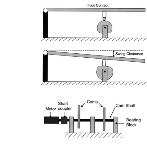
In order for the treadmill to meet the requirements to deliver therapy, it must provide a stable walking surface that is parallel to the ground, allow adequate clearance for a leg to swing without knee flexion, and return to the parallel position in time for the heel strike of the next stride. The average walking speed of a healthy individual is 3.3 ft/sec (1 m/s), but studies with stroke patients are often completed at speeds between 0.29 and 1.17 ft/sec (0.09 - 0.36 m/s) [38]. An appropriate treadmill must be able to operate in this range for use by affected subjects. Figure 3-4 shows the required foot clearance for the 9 9th percentile male and 1st percentile female for both
a 100 and 150 toe-off angles.
Figure 3-4. Foot clearance and time requirements for treadmill actuation.
While 100 is the common angle for healthy individuals walking at about 3.3 ft/sec (1 m/s), 15* was included as a factor of safety. These trajectories were calculated by treating the leg and heel as a simple pendulum acting under gravity with Equations 3.1 - 3.3:
T = 2rc L
g
(eq.
3.1)
(eq.
3.2)
MaxClearance = L
(1-
cos 0,)
(eq.
3.3)
Where T is the full period of the leg (a swing phase would be of the full period of a pendulum), 0(t) is the angle of the leg at time t, Q, is the toe-off angle, L is the length of the leg, and g is the gravity constant (32.2 ft/sec2 or 9.81 m/s2). For the
9 9th percentile male with a 150
toe-off, 1.5 inches (3.8 cm) of swing clearance will be adequate. Also, for the 1't percentile
female, the treadmill must be actuated in 0.14 seconds in order to provide swing clearance and return to parallel in time for foot strike.
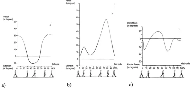
Figure 3-5 shows the angles of the hip, knee, and ankle throughout a healthy gait cycle [5].
Fleoto (in degrees) 5D- 40- 20- 10-Extenon _eUeWcyl (in degrees) 0 10 20 30 40 50 60 70 00 90 100% (in degrees) 7 0- 50-40 30 1 20- 10-Extension 10 -- r - - Gi yl (in degrees) 0 10 20 30 40 50 00 70 00 90 100% Dorsifexon (in degrees) 0 2y3e Gait0 0 10 20 30 40 50 60 70 80 90 100% a) b) c)
Figure 3-5. Angles during a healthy gait cycle at about 3.3 ft/sec of, a) the hip, b) knee, and c) ankle.
The walking surface of the treadmill must be long enough for the subject to be able to complete a normal stride, with an allowance for missteps, and the width must accommodate stance width. The recommended minimum treadmill length is about 60 in (150 cm) with a width of 25 in (60
cm) [38]. It should be noted that the width of the treadmill should not exceed 29.5 in (75 cm) because this will require the therapist to lean forward in order to access the subject's legs [15].
BowFlex® TreadClimber®
A hinged, split treadmill is available on the market as an exercise machine called the BowFlex TreadClimber (Figure 3-6). This treadmill is similar to the K'nex proof-of-concept with two treadmills hinged at one end and driven by the same motor. Since this device is marketed for home use, it is designed for disassembly so that it can be shipped in flat, compact boxes. Another advantage of being designed for home use is that it has a small footprint compared to many treadmills with a width of 28.5 inches (72.4 cm) and a length of 46 inches (116.8 cm).
b)
Figure 3-6. a) BowFlex@ TreadClimber@, b) TreadClimber® in Use.
In contrast to its use for exercise where the adjustable cylinders provide resistance as the user steps and pushes the treadmill down so it is parallel to the ground, a patient would be facing in the opposite direction and the treadmills would be externally actuated up and down. The cylinders, display support columns, and handles would be removed to accommodate this change and the display and controls would be relocated for easy access by a therapist.
The TreadClimber treadmill length is 40 inches (101.6 cm), which will be adequate for the testing of healthy patients and since the body weight support system will prevent the subject from shifting forward or backward along the treadmill. The total treadmill width is 18.5 inches (47 cm) which will allow the therapist easy access to the subject's legs.
A BowFlex TreadClimber TC3000 was chosen to serve as the base for the full scale proof-of-concept prototype. Additional product specifications are listed in Appendix A.
3.3.2 Body Weight Support
Many patients are not able to stand under their own weight when they begin physical therapy or they may need assistance maintaining balance. A body weight support (BWS) system needs to provide enough support to unload up to 100% of the patient's weight and keep the patient safe from falls while not interfering with the required ranges of motion. Using an upper limit of a 350 lbs (158.8 kg) patient, and a factor of safety of 3 for fall prevention, the BWS must be able to withstand up to about 1050 lbs (476.4 kg).
Providing too many degrees of freedom may make it difficult for a patient to maintain stability, but restricting all pelvic motion will not create a realistic walking environment. A BWS should allow enough vertical movement of the patient's center of gravity to permit normal gait without causing a loss of posture. As discussed in Chapter 2, a common rule of thumb is to allow +/- 2 in (5 cm). A study of 25 healthy men and 25 healthy women measured the average vertical displacement as 1.46 +/- 0.35 in (3.7 +/- 0.9 cm) and 1.06 +/- 0.24 in (2.7+/- 0.6 cm) respectively [38]. Pelvic tilt is also important to maintaining balance and about 5* is required on average. In addition, rotation about the vertical axis of +/- 40 is important for the swing phase and advancing the foot for the next step.
This structure must fit around the treadmill assembly which is 24 inches (61 cm) wide, but still be narrow enough to fit through a standard door frame which is 35 inches (89 cm) wide and 83 inches (211 cm) tall so it can be moved easily. The design chosen to actuate the treadmills will
determine the height above the ground the walking surface will be which will dictate the required height of the body weight support.
3.4 Actuation Design
The key to the success of this device is to actuate the treadmills so that they are parallel to the ground during foot stance, provide an adequate swing clearance of 1.5 inches (3.8 cm), and return to the parallel position for heel strike. Load calculations were completed using the 18 lb
(8.2 kg) weight of the treadmill alone, and assuming the subject weighed 350 lbs (158.8 kg). The following are eight design configurations that are able to produce this required motion. Each concept's strengths and weaknesses are discussed.
3.4.1 Lead and Ball Screws
Lead screws are able to convert the rotary motion of a motor into precise linear motion and are capable of withstanding large axial loads. The two components of a lead screw are the screw and the nut (Figure 3-7). The screw diameter, pitch, and material are chosen by the loading conditions and speed requirements. The nut material is chosen to complement the screw and is often softer so that the threads are not quickly worn.
Figure 3-7. Lead screw example.
Ball screws are similar to lead screws, but they also contain ball bearings in the nut (Figure 3-8). These bearings reduce the friction between the screw and the nut, but also increase the cost.
Screw Shaft
Steel Balls
,-Nut
Figure 3-8. Ball screw.
Figure 3-9 shows a schematic with a lead screw and a motor actuating each of the treadmills.
Figure 3-9. Lead screw design configuration.
In order for the required clearance between the treadmill and the lead screw, the screw is positioned to the side of the treadmill with a distance between the center of the treadmill and lead screw of about 6 inches (15.2 cm). This creates a moment or an overturning load (Figure 3-10) of 108 in-lb (12.2 Nm) for only the treadmill load and up to 2208 in-lb (249.5 Nm) if the treadmill is carrying the full weight of the user. This may cause the screw to jam.
Figure 3-10. Lead screw jamming under a moment load.
Since lead screws inherently can only support axial loading, one design change that could greatly reduce this moment load is to have two lead screws for each treadmill (Figure 3-11). Although this makes the loading on the screws a thrust load, it doubles the number of components
![Figure 3-21. Device to test the mechanics of running under simulated low gravity [41].](https://thumb-eu.123doks.com/thumbv2/123doknet/14685295.560102/57.918.284.643.117.385/figure-device-test-mechanics-running-simulated-low-gravity.webp)
![Figure 4-10. Pressure angle of an oscillating roller follower [39].](https://thumb-eu.123doks.com/thumbv2/123doknet/14685295.560102/70.918.222.705.117.468/figure-pressure-angle-oscillating-roller-follower.webp)
![Figure 4-12. Cam profile of an oscillating roller follower [39].](https://thumb-eu.123doks.com/thumbv2/123doknet/14685295.560102/72.918.122.756.114.572/figure-cam-profile-oscillating-roller-follower.webp)