Design of a High Speed Planing Hull with a
Cambered Step and Surface Piercing Hydrofoils
by
Leon Alexander Faison
Bachelor of Science in Electrical Engineering, Christian Brothers University, 2007
MASSAOHU~YS iSTI TUT E
OF T EG'41LOGY
AUG 15 2014
U L RA RIES
Submitted to the Department of Mechanical Engineering in Partial Fulfillment of the Requirements for the Degrees of Naval Engineer and Master of Science in Mechanical Engineering
at the
Massachusetts Institute of Technology June 2014
2014 Leon Alexander Faison. All rights reserved.
The author hereby grants to MIT permission to reproduce and to distribute publicly paper and electronic copies of thj thesis docum nt in whole or in part in any
mediu;p ow known o ereafter created.
Signature redacted
Signature of Author
S
Certified by_
Leon Alexander Faison Department of Mechanical Engineering
ignature redacted
May 9, 2014
Chryssostom4s Chryssostonlihs, Director of MIT Sea Grant Doherty Professor of Ocean Science and Engineering Professor of Mechanical and Ocean Engineering
Signature redacted
Thesis Supervisor Certified byAccepted by
Stefan/Brizzolarh! Assistant Director for Research at MIT Sea Grant Research Scientist, Depart nt of Mechanical Engineering
Signature redacted
David E. Hardt Ralph E. and Eloise F. Cross Professor of Mechanical Engineering Chairman, Departmental Committee on Graduate Students
Design of a High Speed Planing Hull with a Cambered Step and Surface Piercing Hydrofoils
by
Leon Alexander Faison
Submitted to the Department of Mechanical Engineering
on May 9, 2013 in Partial Fulfillment of the Requirements for the Degrees of Naval Engineer and Master of Science in Mechanical Engineering
at the Massachusetts Institute of Technology Abstract
Design of a high speed planing hull is analyzed by implementing a cambered step and stem, surface piercing hydrofoils, commonly known as a Dynaplane hull. This configuration combines the drag reduction benefits of a stepped hull with a fully ventilated afterbody by using a stem stabilizer. The largest obstacle with this design is maintaining trim control and stability at high speeds. There has been limited research on the Dynaplane design since Eugene Clement first conducted tow tank tests in the David Taylor Model Basin (DTMB) in the 1960s. Modem experimental methods such as computational fluid dynamics (CFD) allow the designer to run multiple simulations at once while testing a variety of parametric variables. The analysis will combine theoretical, empirical, and computational methods to determine the hydrodynamic characteristics of the design and develop a new Dynaplane configuration that allows for speeds in excess of 50 knots. The design approach begins with using a reference hull named Model
5631 from a small systematic series of resistance tests at the DTMB. This modeled hull is based
on the U.S. Coast Guard 47 ft Motor Lifeboat which is a hard chine, deep V planing hull. Clement's Dynaplane design process was followed with exception of the stem stabilizer recommendation. Instead, a surface piercing super cavitating (SPSC) hydrofoil designed by Dr. Stefano Brizzolara was used. These designs further improve upon the powering requirements of a conventional planing hull by effectively increasing the lift to drag ratio. A commercially available CFD software program called Star-CCM+ is used for the computational portion. The computational model is first validated using results from the Model 5631 tow tank tests. Three series of CFD tests were then conducted on the new Dynaplane design; which include developing wake geometry predictions for a swept back stepped hull, and then varying the trim angle and longitudinal center of gravity. These tests were run at an FnV=5 in a calm sea state. Results from the analysis demonstrate the benefits of a fully ventilated afterbody using the SPSC hydrofoils and predict the hydrodynamic behavior for the new design. Also, the results extend the range of application of Clement's Dynaplane design to hulls with 20 degree deadrise. This thesis gives naval architects design guidance for such a hullform and demonstrates the potential of CFD as a tool for analyzing these parametric variables.
Thesis Supervisor: Chryssostomos Chryssostomidis
Acknowledgements
This thesis would not have been possible without the guidance and support of so many individuals and organizations who helped the author achieve its completion. The sincerest appreciation is expressed to the following:
" To my family and friends, for their love and support.
* To Dr. Stefano Brizzolara, for his enthusiasm, confidence, and guidance in the accomplishment of this research. Without his technical expertise, this thesis would not have been possible.
" To Dr. Chryssostomos Chryssostomidis, for giving me the opportunity to work with the
bright minds within MIT's Sea Grant program.
* To the members of the Innovative Ship Design Lab, Luca Bonfiglio, Giuliano Vernengo, Zvi Sheingart, and Vasileios Georgiadis, who all provided contributing efforts and feedback on the research.
" To Dr. Donald L. Blount, for his practical experience, insight and technical knowledge on
planing hulls.
" To CAPT Mark Thomas and CDR Jerod Ketcham, for setting the example of the U.S. Navy's
Core Values and teaching the Naval Officers in the 2N Program about naval construction and engineering.
" Lastly, the author would like to thank the United States Navy for sponsoring his graduate
Table of Contents
Abstract --- 3 Acknowledgements---5 Table of Contents --- 6 List of Tables --- 7 List of Figures --- 8 Nomenclature --- 10 Chapter 1 - Introduction--- 11 1.1 Background --- 111.2 Planing Hull Dynamics --- 12
1.3 Motivation--- 16
1.4 Design Procedure --- 18
Chapter 2 - Numerical Model Validation--- 20
2.1 Hull Selection --- 20
2.2 Computational Engineering--- 21
2.3 CFD Validation --- 24
2.4 Performance Enhancements --- 29
Chapter 3 - The Dynaplane Configuration --- 31
3.1 Clement's Dynaplane --- 31
3.2 Cambered Step Design --- 32
3.3 Afterbody and Stern Stabilizer Design --- 40
3.4 Wake Profile Comparison from Empirical and Computational Methods--- 46
3.5 Final Design --- 55
Chapter 4 - Hydrodynamic Analysis --- 56
4.1 Stability Concerns --- 56
4.2 Previous Methods for Predicting Dynamic Stability--- 57
4.3 Model 5631 Dynaplane Pitch and Heave Moment Considerations --- 60
4.4 Model 5631 Dynaplane Longitudinal Center of Gravity Analysis --- 68
4.5 Final Results Comparison to Reference Hull--- 72
Chapter 5 - Conclusions--- 73
5.1 Summary --- 73
5.2 Future Work --- 73
Appendix A: Spray Formation for Model 5631 Dynaplane --- 75
Appendix B: Empirical Resistance MATLAB Code --- 76
List of Tables
Table 1: U.S. Coast Guard 47' MLB Model Variants... 20
Table 2: Brizzolara and Federici's Drag Reduction Results ... 30
Table 3: Cambered Step Variant Generation... 32
Table 4: Chosen Design Parameters for Dynaplane Configuration... 32
Table 5: Application Limits for Savitsky and Morabito's Empirical Method ... 47
Table 6: Primary Characteristics for the Model 5631 Dynaplane Design ... 55
Table 7: Moment Contributions of Model 5631 Dynaplane... 65
List of Figures
Figure 1: Hullform Categories for Seagoing Vessels ... 12
Figure 2: Pressure Distribution on Flat Planing Surface ... 13
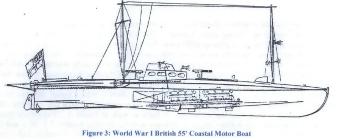
Figure 3: World War I British 55' Coastal Motor Boat ... 13
Figure 4: RT/W Comparison for Changing Deadrise and Stepped Hulls ... 14
Figure 5: Transport Efficiency, ET, for High Speed Vessels ... 15
Figure 6: Drag to Lift Ratios for Varying Deadrise on a Prismatic Planing Surface ... 18
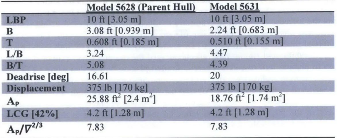
Figure 7: Model 5631 Profile and Body Plan Views and Geometric Parameters ... 20
Figure 8: Illustration of Two-Phases Using VOF Model, a) Unsuitable Grid b) Suitable Grid ... 22
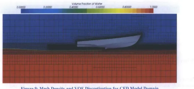
Figure 9: Mesh Density and VOF Discretization for CFD Model Domain... 22
Figure 10: Prism Layer Mesh Illustration along Planing Surface... 23
Figure 11: Virtual Tow Tank with Half Hull Arrangement... 24
Figure 12: Resistance Validation Results for 375 lb Model 5631 ... 25
Figure 13: Trim Validation Results for 375 lb Model 5631 ... 25
Figure 14: Heave (Vertical Translation) Validation Results for 375 lb Model 5631 ... 26
Figure 15: Wetted Area Validation Results for 375 lb Model 5631... 26
Figure 16: Resistance Validation Results for 483 lb Model 5631 ... 27
Figure 17: Trim Validation Results for 483 lb Model 5631 ... 27
Figure 18: Heave (Vertical Translation) Validation Results for 483 lb Model 5631 ... 28
Figure 19: Pressure Coefficient and Volume Fraction of Water on 3751b Model 5631... 28
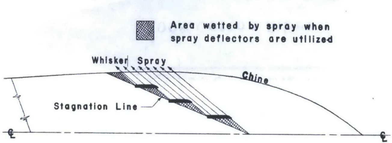
Figure 20: Reduced Wetted Surface Area Due to Spray Rails/Deflectors ... 29
Figure 21: High Speed (50 kts) Patrol Craft with 20 degree Deadrise ... 29
Figure 22: Wetted Area and Pressure Distribution Comparison for Stepless and Stepped Hulls 30 Figure 23: Comparison of Calculated and Experimental Results of L/D for Johnson 3-Term Cambered Surface and a Flat Plate, AR = 2.0 ... 33
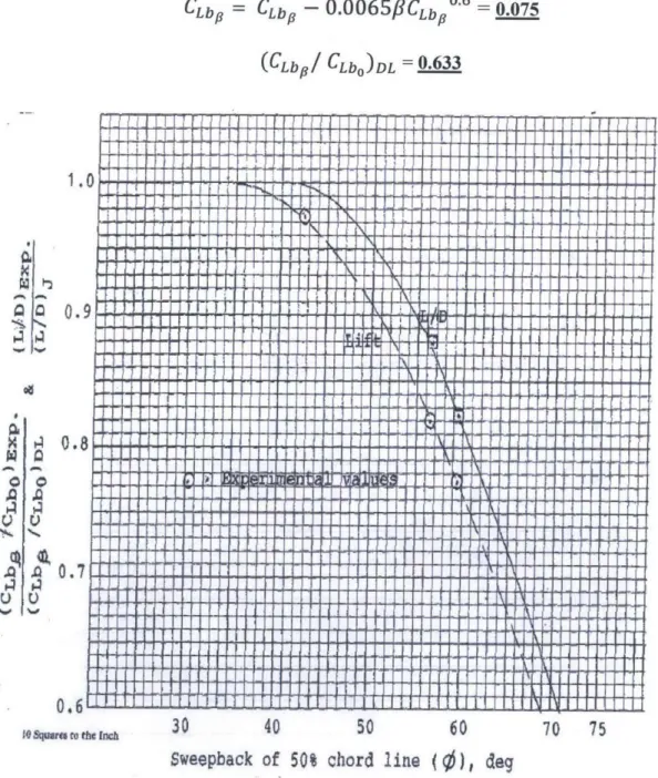
Figure 24: Swept Back Angles for Cambered Planing Surface, Plan View ... 34
Figure 25: Correction Value for Swept Back Angle to Lift and L/D Ratio... 35
Figure 26: L/D Ratio Versus CLbo Results for a Johnson 3-Term Profile, AR = 2... 36
Figure 27: CL,d Versus Aspect Ratio for a Johnson 3-Term Profile, c=2.5 deg ... 37
Figure 28: Center of Pressure Location Versus CLbO for a Johnson 3-Term Profile, -=2.5 deg .. 37
Figure 29: Length Dimensions on Cambered Step ... 38
Figure 30: Camber Profile with Johnson 3-Term Equation, Cl,d=0.236... 39
Figure 31: Plan, Profile and Body Plan Views of Preliminary Cambered Step on Model 5631 .. 39
Figure 32: Dimensionless Resistance Versus Speed Curve for Dynaplane Configured Boat... 40
Figure 33: Surface Piercing V Hydrofoil with a 30 degree Dihedral ... 41
Figure 34: 2D Profile Examples of Super Cavitating and Sub-Cavitating Hydrofoils... 41
Figure 35: 2D Profiles of Super Cavitating Hydrofoils at Sub-Cavitating Speeds ... 42
Figure 36: 2D Profiles of Super Cavitating Hydrofoils at Cavitating Speeds ... 43
Figure 37: Ventilation Formation from CFD Simulation ... 44
Figure 38: Ventilation Formation from Cavitation Tunnel Tests ... 45
Figure 39: Design Draft for Tested Submerged Lengths of Brizzolara's Hydrofoil... 45
Figure 40: Stepped Hull Afterbody Orientation with a Stem, Submerged Hydrofoil... 46
Figure 41: Wetted Area for Parameter Calculation ... 47
Figure 42: Reference Longitudinal Axis for Wake Profile... 47
Figure 44: Flow Direction for Camber and No Camber ... 49
Figure 45: Wake Profile Comparison of Transverse Step vs Swept Back Step at Centerline, 3.5 deg T rim ... 4 9 Figure 46: Wake Profile Comparison of Transverse Step vs Swept Back Step at 1/4 Buttock, 3.5 deg T rim ... 50
Figure 47: Wake Profile for Swept Back Step (No Camber) at 3.5 deg Trim... 50
Figure 48: Wake Profile for Cambered Step at 3.5 deg Trim... 51
Figure 49: Wake Profile Comparison of Steps with Camber and No Camber at 3.5 deg Trim ... 52
Figure 50: Perspective View of Wake Profile from Cambered Step at 3.5 deg Trim ... 53
Figure 51: Bottom View of Wake Profile from Cambered Step at 3.5 deg Trim... 53
Figure 52: Rendering of SPSC Hydrofoil Used... 54
Figure 53: Vertical and Transverse Positioning of SPSC Hydrofoil's Design Draft ... 54
Figure 54: Plan, Profile, and Body Plan Views of Model 5631 Dynaplane Design... 55
Figure 55: Planing Hull Dynamic Instabilities ... 56
Figure 56: Dynamic Instabilities for Model 5631 Dynaplane Configuration... 57
Figure 57: Dynamic Transverse Instability (DTI) Regions ... 58
Figure 58: Trim versus Speed Curve for Predicting Bow Drop ... 59
Figure 59: Free Body Diagram of Model 5631 Dynaplane ... 60
Figure 60: Drag Force Component of Model 5631 Dynaplane, Run 1 ... 61
Figure 61: Heave (Z Translation) Monitor for Model 5631 Dynaplane, Run 1 ... 62
Figure 62: Pressure Coefficient and Volume Fraction of Water @ 3.5 deg Trim and FnV=5... 62
Figure 63: Drag Force Component of Model 5631 Dynaplane, Run 2 ... 63
Figure 64: Heave (Z Translation) Monitor for Model 5631 Dynaplane, Run 2 ... 63
Figure 65: Drag Force Component of Model 5631 Dynaplane, Run 3 ... 64
Figure 66: Heave (Z Translation) Monitor for Model 5631 Dynaplane, Run 3 ... 64
Figure 67: Total Pitching Moment for CFD Runs 1-5... 66
Figure 68: Depiction of the Four Sections Analyzed... 67
Figure 69: All Contributing Forces to Pitching Moment for Model 5631 Dynaplane ... 67
Figure 70: Longitudinal Stability Margin, h, versus Trim Angle ... 68
Figure 71: Trim Monitor for Model 5631 Dynaplane, Run 6... 69
Figure 72: Heave (Z Translation) Monitor for Model 5631 Dynaplane, Run 6 ... 69
Figure 73: Trim Monitor for Model 5631 Dynaplane, Run 11... 70
Figure 74: Heave (Z Translation) Monitor for Model 5631 Dynaplane, Run 11 ... 71
Nomenclature
a Angle of attack
AR Aspect ratio, b2/S AP Projected chine area
Bpx Maximum beam over chines
b Breadth of planing surface
Bf Beam between hydrofoils Deadrise angle
BOA Beam overall
CD Drag coefficient, D/(0.5pv 2s
CL Lift coefficient
CLbO Lift coefficient of flat plate CLbp Lift coefficient of hull with a CLd Lift coefficient for a 2D cam
Cv Speed coefficient with respe
c chord length of cambered cu
A Displacement of vessel
D Drag Force
FnL Froude number using length FnV Froude number using underv g acceleration due to gravity y Angle between the spray roo Lc Length of wetted chine
1c, Distance from transom to ce
Lk Length of wetted keel
Lp Length of project chine area Ir Length of cambered surface it Length of cambered surface lm Mean wetted length of plani
LCG Longitudinal distance from t
LOA Length overall
LWL Length along the waterline Swept back angle between 5 Re Reynolds number, vL/v
RT Total resistance
p Density of fluid
S Wetted area of cambered pla
e
Swept back angle between tI T Trim angle of planing hullv Velocity of fluid flow
U Kinematic viscosity of fluid
V Underwater volume of pla
W Weight of planing hull
)
given deadrise angle bered planing surface
ct to hull's beam, v/-g
rve
at waterline, v/J gLWL
vater volume, V/,fg ri t line and centerline
riter of pressure
at the root or keel at the tip
ig surface or Mean Hydrodynamic Chord (M
ransom of the center of gravity
0% chord line and a transverse line
ning surface
he trailing edge, or step, and a transverse line
ning hull
Chapter 1 - Introduction
1.1 Background
The desire for maximizing speed in a maritime vessel has been around since the advent of naval architecture. It was the thought in the mid-1800s that a vessel's hull speed could not be surpassed. Early naval architects considered a vessel's hull speed as the speed at which the wavelength of the wave generated by the bow is equal to the ship's length. Pioneers such as John
I. Thornycroft, Charles D. Mosher, and Nathanael G. Herreshoff proved that a vessel could
exceed its hull speed with efficient hull design and modem engine technology at the time. A commission in the 1860s was formed by the Institution of Naval Architects in England to identify the most efficient hull shape. Model tests conducted by William Froude provided a convention for predicting the behavior of full scale ships based on scaled models. This new dimensionless parameter or Froude number is the vessel's speed, v, divided by the square root of the gravity contact multiplied by the ship's length, L.
V
FnL =
There was now a testing parameter to be used for practical experimentation to determine efficient hull designs which could achieve high speeds. Most of the earlier examples of exceeding hull speed used round bilge hulls. Hard chine or flat bottom bottoms didn't begin to surface until the beginning of the 2 0th century with their first application being tested on seaplanes. During the
1930s and throughout World War II, many efforts were focused on planing technology. Institutions like the National Advisory Committee for Aeronautics (NACA) began extensive testing of this technology, first beginning with aircraft technology but later being incorporated in high speed marine vessels. The researchers of this period began to understand the effects of loading and powering for high performance planing vessels. These planing hulls depended largely on hydrodynamic forces as opposed to hydrostatic forces associated with displacement vessels. Researchers began to determine the need for the development of a more appropriate speed coefficient to study and compare these planing hulls. Two examples are shown in the equations below, the volumetric Froude number, FnV, and a speed coefficient with respect to the hull's beam, Cv. Using dimensionless parameters based on a vessels weight or beam was useful in predicting planing hull performance for a range of hull sizes and especially in model tests which predicted early hydrodynamic characteristics of planing hulls.
V V
FnV = =
Cv
-Progression of propulsion and hull design technology saw a direct correlation with achieving high Froude numbers. In 1963, Daniel Savitsky completed and published a widely accepted paper called "Hydrodynamic Design of Planing Craft." His paper conducted an empirical approach for predicting the performance on a variety of simple prismatic planing hulls. The success and acceptance of his research sparked a sudden surge of model test data at the U.S. Navy's David Taylor Model Basin, DTMB, located in West Bethesda, MD. Planing hull technology owes much of its beginnings to those early researchers, Savitsky, Clement, Blount
and many others at the DTMB. The focus on improving powering in planing craft consisted of full scale hulls as well as experimental models. Performance of planing hulls not only included maximizing speed but it also focused on stability at speed. Empirical equations were developed based on those early series of model tests which are able to solve hull resistance and trim at a given speed, as well as vertical accelerations and stability in a given seaway.
1.2 Planing Hull Dynamics
With the accomplishment of exceeding hull speed, research then focused on understanding the dynamics of planing hulls and optimizing the geometry to develop an efficient design. A great illustration of the types of seagoing vessels associated with certain speeds ranges is shown in Figure 1. Once you move into the planing regime, hydrodynamic forces play an important role in the performance of the hull. In this chapter, we will analyze the dynamics specifically for planing hulls.
SEA00G VESSES
(Sudffce. SV"0 Effect, SU*4#I)
AieftIt
t
Surf&CI
S cu'honI
SEE ~~I C ME S Ie ot A C4metI
I
C support Hy*dyn' supportl@ppo
I ,ffect ipa mn pca 0
Hydroftfli UPd
Swial dDip=40 me
sitPning huib Cubabma
(ti hulI
I-
-pieKcina foils
Kn*Us M0100 0-40 30-15
Figure 1: Hullform Categories for Seagoing Vessels
To better understand the dynamic forces of planing hulls, early researchers such as Savitsky, conducted series of tests with a flat plate, which is equivalent to a zero degree deadrise hull. From these tests, one was able to determine the fluid flow across such a hull and the dominant forces being applied. In Figure 2, the largest forces applied to the wetted area of that flat plate, or planing surface, are at the stagnation line. The stagnation line is where the local velocity of the flow field is essentially zero, and can also be described as where the flow separates into the water spray and the fluid flow moving aft along the hullform. This concentration of pressure provides majority of the hydrodynamic lift needed to enter the planing regime, but also contributes to majority of the drag. In this example, a flat plate is traveling through water, but from Figure 2 the
trim angle determines the magnitude of this pressure concentration. The idea behind the Dynaplane configuration is to take advantage of this concentration of pressure and design a lifting surface which possesses a high lift to drag ratio. This type of lifting surface can be likened to an aircraft wing, which is cambered; but first, the evolution of improving powering requirements starting from the flat plate will be discussed.
r PRESSURE DISTRIBUTION
I 2
LEVEL WATER
SURFACE 8=SPRAY THICKNESS STAGNATION LINE SPRAY ROOT
Figure 2: Pressure Distribution on Flat Planing Surface
The early seagoing vessels that exceeded their hull speeds were round bilge hulls. Compared to large displacement vessels, high speed round bilge hulls take advantage of a streamline design; but the hullform is still limited by the frictional resistance of the wetted area. Early solutions to this problem involved creating a stepped hull, as shown in Figure 3. The Thornycroft Company developed and built these boats for the British Royal Navy. The stepped hull takes advantage of reducing the wetted area, thus decreasing the resistance or drag on the hull.
Figure 3: World War I British 55' Coastal Motor Boat
Further testing began to discover the reduction of wetted area can be achieved by diverting the water spray away from the hull. From this conclusion, the hard chine planing hull began numerous testing at the DTMB (Savitsky, 1964; Clement and Blount, 1963). These tests changed several hull parameters such as Ap, Lp, Bpx, and Lp/ Bpx. One of the goals to the model series of
tests was to determine the effects of changing the wetted area and how to design the hull's geometry to ensure a minimum frictional resistance.
7Dftp-vee With BPra nkls Davidmo Lab I T
Model No. 2879. Deadrift - 22 d691 1 0.3 D B Sed s62; ModelNo. 4667-1.
Deadrise -12.5 de&.
(D0Swedish Tank Model No. 469-A;
FbW d tbody- Dvadd" = 75 deg
DTMB Model Wo 5115; with camber
-AW trim Cotrol Deadrise -75 do& Unstepped
_________________________hulls 71 1TL I I I I I I I I I I I I J1 1 --- 7 I 1*f7 l v i ii 0.2 win 0.1 0 L 0 2 3 VV 4
Figure 4: R1/W Comparison for Changing Deadrise and Stepped Hulls
With the introduction of proven model test results and certain design features which improve the overall performance of planing hulls, further testing was demanded to expand the range of parameters as applications of planing hulls grew. For example, high speed vessels were needed in offshore operations, primarily for military purposes at first. A majority of the sponsorship of these series of model tests were funded by government organizations to be intended for military use. When encountering a given sea state while operating offshore or in a coastal region, hulls with a higher deadrise angle perform better, with improved ride quality as the impact of wave is reduced. However, there is a disadvantage with having a deep V hull; a higher deadrise angle causes more wetted area. Therefore, the problem of increased wetted area has returned. The concept of stepped hulls was applied to deep V hulls as well. In Figure 4, Clement compared hullforms with steps and without steps, in addition to three deadrise angles: 7.5, 12.5 and 22 degrees. The results from the figure below were conducted at DTMB, the Davidson Lab's tow tank, and a tow tank in Sweden. First, their results show a clear divergence between stepped hulls and unstepped hulls. Next, the added resistance by increasing the deadrise angle is also shown. It can be concluded from this figure that stepped hulls have approximately 50% reduction in total resistance. Also, a step with camber and aft lifting surface provides even further drag
1
hulls
reduction at high speeds. Stepped hulls start to show benefits at FnV > 3; however, more recent
analysis shows that stepped hulls become more advantageous at FnV > 5, shown in Figure 5.
There will always be room for improvement in the performance of planing hulls especially when they're pushed to the maximum safe operating envelope.
As shown in Figure 1, high speed vessels are divided into more categories than just planing hulls. In order to better compare the performance characteristics of high speed vessels such as planing monohulls, surface effect ships, or catamarans, a parameter called a vessel's transport efficiency is introduced. This allows the designer to give a non-dimensional value to the vessels ability to efficiently carry fuel, cargo, and payload. The transport efficiency is a ratio of the overall propulsive efficiency, rj, divided by the dimensionless bare hull resistance to weight ratio. Higher transport efficiency is desired and in Figure 5, various types of hullforms are analyzed.
RT toSW 40 10 S Z
muyy ~ ~ ~ o-V in,. HA vvrwwm L w y pyy wn iiw -UUI
ImO Z . m~pSJ N I----I.IW u~ 1 K I I 0 -0 0 . 6; 4 ; f 9; ; so d At 0~ a9 0 6 e r ,d
Figure 5: Transport Efficiency, E1,, for High Speed Vessels E I
It can be shown below that stepped hulls begin to perform better than other hullforms, such as hard chine hulls, SES and catamarans, at FnV values greater than 5. For this reason, the incorporation of a stepped hull into Model 5631 powering improvements was necessary. The speed coefficient the hull was designed towards was FnV = 5. For the purpose of this thesis and later studies, defining design requirements early allows for an overall efficient testing and evaluation procedure.
1.3 Motivation
The motivation for this thesis originates from reading published papers on planing hull technology and meeting the goals of MIT's iShip Lab, directed by Dr. Stefano Brizzolara. This thesis begins with a new design of a Dynaplane configured planing hull, and then explores the potential improvements for very high speed planing hulls, utilizing a fully ventilated afterbody, surface piercing hydrofoils, and a swept back stepped hull with a cambered planing surface. Savitsky expressed the importance of using model test data for the design of planing hulls utilizing the benefits of hydrofoils (Savitsky, 1964). Later this thesis uses a computational model to determine the advantages of these innovative design features.
Computational fluid dynamics (CFD) in numerical models gives the designer a wider range of possibilities than physical model testing. It is of particular importance to the author to understand
and demonstrate the capabilities of CFD models and its potential in studying planing hull and hydrofoil technology. Many of the earlier model testing data, Series 62 and Series 64, are still used by designers today; and the methods used for predicting performance rely on empirical equations which have a limited range of applicability. This thesis attempts to show the clear advantages of CFD and the accuracy it can achieve in predicting key performance parameters for planing hulls. CFD allows the naval architect to test his design in potentially longer simulations that capture more data, all at a relatively low cost.
The cost of construction and risks involved with full scale tests has inhibited most of the advancement in technology of planing hulls. This leads to the majority of newly derived empirical and analytical methods being based on physical model testing in tow tanks. With the demand for more modem technology and improvement in the planing hull industry, the cost of construction of model and tow tank availability has also led to a downshift in improving technology. Savitsky and Morabito said, "[We] encourage the development of CFD since such a tool may be useful in extending the range of parametric variables at modest cost" (Savitsky and Morabito, 2009). It is not to say that physical model testing will be obsolete but the reliance and dependability of CFD models is demonstrated to be much more powerful in its capability. Computational modelling allows for real time simulation adjustments. Results can be produced for a wider range of parametric variables in less time because you can make adjustments to the model geometry and run those changes in a short period of time; whereas, a physical model requires a new model constructed for each iteration. CFD allows for more complex geometry and the possibility for longer simulations. A computational model doesn't come without any disadvantages. It is computationally expensive, meaning it requires several cores of processors to calculate each time step. Also, it requires basic knowledge of numerics and a level of expertise to operate the software and code. However, newer CFD tools, such as Star-CCM+, give the user a
graphical interface which is intuitive and allows for functionality similar to typical computer aided design (CAD) programs.
Besides the clear advantages and disadvantages for using a computational model for solving planing hull dynamics, the planing hull industry requires the level of accuracy and fidelity of each model to be sufficient. For this reason, this thesis validates the computational model used in the design and compares it with empirical prediction methods used widely throughout current research (Brizzolara and Serra, 2007). In their research, a RANSE solver was used to test a prismatic planing hull. Their results were then validated using experimental data and empirical methods. The numerical measurements were within 10% of experimental and empirical results. Later refinements of the numerical model implemented on systematic planing hull series (Brizzolara et al, 2009) and on real planing crafts with various types of appendages lead to an increase of the accuracy to the order of 3% on drag (Brizzolara and Villa, 2010). The accuracy and fidelity of their results prove that computational models can predict the proper physics of these types of fluid problems.
A goal of this thesis is to continue the discussion of using computational models for planing hull
performance predictions. With results on a 20 degree deadrise hull validated in Brizzolara and Serra's analysis, the validation of further model tests is encouraged. In Chapter 3, the
Star-CCM+ computational model will be validated using the experimental results from the small
systematic series of model tests. These simulations also allow the designer to test changes in specific parameters to the hull, for example trim, LCG, and hull geometry. Additional motivation is encouraging the continued use of CFD modelling, so that it can be used to accurately predict performance of planing hulls with low levels of speculation or uncertainty.
At high speeds, planing hulls experience hydrodynamic lift along with the associated drag component. Proper balance between lift and drag must be achieved to establish an effective design. Lift to drag ratios in marine vessels, such as planing hulls, are quite different than their aircraft counterparts. A higher specific gravity in the medium causes increased drag with a nonlinear lift relationship. Also, variations in the hull's deadrise largely affect the lift that can be produced. Early model tests produced empirical equations for prismatic planing surfaces but modem, high speed planing hulls largely differ from the typical prismatic hull or flat plate used in those earlier model tests (Clement, 1966). In Clement's research, lift to drag ratios greater than
10 were desired for stepped hulls. However, certain hull parameters at speed such as trim and
deadrise play an important role in achieving high lift to drag ratios. In Savitsky's "Hydrodynamic Design of Planing Hulls," the drag to lift ratios of planing hulls with variations in deadrise, trim and beam are analyzed. The results from this analysis are shown in Figure 6 below but in an inverse form, drag to lift.
A design goal of this thesis is to concentrate improving powering requirements from a more
novel approach. Traditionally, planing hull design focused on optimizing the running trim to achieve the minimum amount of drag with maintaining a proper lift force. In Figure 6, for a flat plate to achieve the smallest drag to lift ratio, it must travel at a running trim of approximately 4 degrees. The novel approach presented in this thesis is to achieve reduced drag by increasing lift and reducing the wetted area as opposed to finding that optimum running trim angle.
0.20
02 - 0 * BEAM-5 I R 20 EAM-10'
TOTAL DRAG / TOTAL DRAG
0.16
.4
VISCOUS DRAG VISCOUS DRAG
008-V r TTAN TANr
0Cr
PRESSURE DRAG PRESSURE DRAG
0
0 2.0 4.0 6.0 8.0 0 2.0 4.0 6.0 8.0
TRIM ANGLE, DEGREES TRIM ANGLE, DEGREES
Figure 6: Drag to Lift Ratios for Varying Deadrise on a Prismatic Planing Surface
The inception of stepped hulls took advantage of this reduced wetted area and found that the pressure on the afterbody of planing hulls only accounted for less than 10% of total pressure on the planing surface. In Figure 2, it can be seen that the majority of this pressure on the planing surface is towards the front end at the stagnation line. The new Dynaplane design presented in this thesis takes advantage of the reduced wetted area from a step but incorporates a cambered surface to provide additional lift at a designed trim angle. Therefore, the benefits of this novel approach allow the designer to specify a running trim angle and then design a cambered lifting surface to provide the lift necessary to achieve high lift to drag ratios.
1.4 Design Procedure
Testing a new design begins with the selection of a reference hull, then continuing with
validation of model before the hydrodynamic analysis can start. Model 5631 was selected as the reference hull, which has a 20 degree deadrise, remaining constant throughout much of the wetted area. The newly developed numerical model requires validation in order to assure accuracy and fidelity of the hydrodynamic results. The model test data from a previous study was used to validate the model (Metcalf et al, 2005). In this analysis, attempts were made to take advantage of the Dynaplane configuration and improve upon the parent hull's performance. This conversion uses Clement's method described in detail in his paper, "A Configuration for a Stepped Planing Boat Having Minimum Drag (Dynaplane Boat)." As compared to a prismatic planing surface in Figure 6, the Dynaplane configured Model 5631 should be able to reduce drag
by 20%. Once the Dynaplane design was completed, the hull was then run in the computational model at three trim angles, 3.5, 4.0, and 4.5 degrees, with the hull being allowed to freely heave.
Further testing included three main groups of tests:
1. Five tests with different LCG locations at a given stable trim angle.
[40%, 42%, 43%, 44%, and 46%]
2. Two different trim angle tests with fixing the heave position found at the designed trim of 3.5 degrees. [4.0 and 4.5 degrees]
3. Six tests with fixed trim and heave to determine the wake geometry of a swept back
step and a cambered step.
All these tests provided experimental information in determining the hydrodynamic behavior of
the Model 5631 Dynaplane configuration.
There are three overarching goals to this research. First, to explore the powering improvements of a planing hull through innovative design features, including a cambered step and stem, surface piercing hydrofoils. The design has several advantages over traditional planing hull designs, including the increase of the lift to drag ratio produced by the cambered lifting surface and the fully ventilated afterbody section by use of two stern hydrofoils. Second, the development of computational modeling, specifically CFD, in the study and design of high speed planing hulls. Savitsky, Morabito, and Blount have all encouraged the use and development of computational modeling in planing hull research. There is limited planing hull design using CFD codes. With continued research, validation, and accuracy demonstration, CFD models will become the industry standard in the design and eventual construction of these high speed vessels. Third, to provide a novel approach in determining the drag reduction of planing hulls by increasing the lift coefficient of the planing surface and reducing the wetted area. It is the primary purpose of MIT's iShip Lab to innovate and provide novel solutions to the marine design community.
Chapter 2 - Numerical Model Validation
2.1 Hull Selection
In MIT's iShip Lab, it is our mission to promote innovation in the design of ships. For this thesis, a hard chine deep V planing hull was to be chosen. This thesis provides innovative solutions to improving power requirements; for example, drag reduction through a fully ventilated step and a new Dynaplane configuration. The resistance tests of a small systematic series for the U.S. Coast Guard's 47' MLB was available. It was attractive because it was a modern set of tests, conducted in 2005, and the model used was a seagoing vessel with a hard chine and deep V hull features that met the design requirements. Table 1 lists the characteristics of model variant 5631 and Figure 7 illustrates the hull lines of the model.
Model 5628 (Parent Hull) Model 5631
B 3.08 ft [0.939 m] 2.24 ft [0.683 m]
L/B 3.44.47
Deadrise [deg] 16.61 20
25.88 f[2A4 18.76 ft [1.74 m-]
A,/V2/3 7.83 7.83
Table 1: U.S. Coast Guard 47' MLB Model Variants
2.237
5631, Variant #3 (L/B=4.47, B/T=4.39)
10.000
2.2 Computational Engineering
The study of planing hulls has traditionally been an empirical science. This involves the testing of physical models, whether full scale or scaled versions. There are inherent inaccuracies when experimenting with physical models; for example, calibration of the test equipment and human error dealing with the measurements. These are just a few of the problems a researcher can face when model testing. Computational engineering entered the stage with a revolutionary way to solve complex fluid flow problems. The application of computational models, at first, found itself to be highly inaccurate because of unrealistic physics modelling. However within the past decade, robust solvers have been developed to allow the use of CFD to transition from a purely research tool to a design tool naval architects can use for final design (Brizzolara, 2012). CFD offers a relatively inexpensive and efficient method to produce results in less time than physical model testing. However, these models can be computationally expensive and require a level of knowledge of numerics that the designer may or may not possess.
CFD allows the naval architect to develop models and environments that match real world
problems and systems. Since the early 1980s, numerical algorithms have been generated to solve the fluid flow problems in a complex nonlinear system. First, we must revisit the Navier-Stokes equations and explain the Reynolds' operators which are time-averaged solutions to solve the fluid flow problem in the Navier-Stokes equations based on the assumptions of turbulence (Newman, 1977). The decomposition of this equation developed by Osborne Reynolds approximates these time-averaged solutions for turbulent flows, known as the Reynolds-averaged Navier-Stokes equations (RANSE).
Navier Stokes equation, in Einstein notation:
6ui -= 0 Sxi Sui Sui 1 SP 62 U, -+ u; -= 3x + V 6t x pSx, SxjSXj
Reynolds operators incorporated into Navier Stokes equations, in Einstein notation: SilL -= 0 6xi + _ I + U I , 4 v -+ ' --=X+ 6t 3x-i 6
SxJ
Ppxi
6xj xj Where u(x, t) = f(x) + u'(x, t)Several RANSE solvers have been developed and are available for use in CFD code. Four commonly known numerical algorithms are PHOENICS, FLUENT, FLOW3D, and STAR-CD
(Versteeg and Malalasekera, 1995). All of these methods are based on a finite inertial reference frame. STAR-CCM+ implements these equations in its software to determine quantitatively the performance characteristics of the model. This program consists of several theoretical methodologies to calculate the fluid flow around a body, consisting of a RANSE VOF, or volume of fluid, multiphase model. This type of model allows for a domain to be established with space and time discretization. The advantage of CFD programs, such as STAR-CCM+, is that it allows the user to specify the domain, or inertial reference frame, for which the system will behave. Essentially, we are creating a virtual tow tank. As you can see in Figure 8, two grids are shown containing two phases. The grid on the left, a), is unsuitable because within each cell of the grid the two phases are not interacting appropriately; specifically they do not share the same velocity, pressure, and temperature fields. However, the grid on the right, b), appropriately illustrates the continuity between phases throughout each cell in the grid.
a)
-Phase 1
O O Phase 2
0 0,
Figure 8: Illustration of Two-Phases Using VOF Model, a) Unsuitable Grid b) Suitable Grid
For our virtual tow tank, VOF becomes especially useful because it is ideal for small contact area between the two phases. Meaning, if we maintain a relatively smooth free surface throughout the virtual tow tank, then we can feel confident of the physics in the multiphase model. In Figure 9, the separation between two phases, water (red) and air (blue), is displayed. This spatial distribution between phases is calculated in the CFD software, which is known as the Volume Fraction value. Note the mesh density, which becomes important in capturing accurate fluid interaction between each cell as well as well as the free surface.
Vokzne Fraction of Water
For testing models in virtual tow tanks, mesh density allows for proper velocity and pressure continuity, and the formation of the boundary layer. The space discretization is dictated by two factors, velocity of fluid flow and time. The velocity of fluid flow is defined by the designer or researcher depending on the experiment. The time is determined by the time it takes for the fluid, or material, to pass through each cell in the mesh. The software algorithms solve the RANS equations using an implicit unsteady approach. This requires an iterative process, in which the system is solved for each physical time-step. Within STAR-CCM+, the user is required to set the physical time-step. The accuracy of the time-step size is dependent on the velocity of the flow and cell size. The Courant number is a dimensionless parameter, shown by the equation below, which allows the researcher to understand the validity and accuracy of their mesh. Given a flow velocity, U; time-step, At, and cell size, cs; the Courant number can be calculated. The ratio
must be less than or equal to 1 to ensure fidelity.
U At
Courant Number, - < 1
CS
STAR-CCM+ also allows for several parameters to be adjusted to refine the mesh. The model is placed in the inertial reference frame, whose size is determined to allow for fully developed physical fluid properties. The Dynamic Fluid Body Interaction feature is used in this model to allow the planing hull to freely move while interacting with the fluid around it. Mesh morphing also plays into this complex problem because as the model is free to move, the mesh must be allowed to change around the moving body. The morphing of each cell can become computationally expensive in the model if not properly adjusted and monitored. The boundary layer formation is accounted for by the Prism Layer Mesher, which is illustrated in Figure 10.
Figure 10: Prism Layer Mesh Illustration along Planing Surface
The overall domain is established by setting geometric constraints and then assigning those boundaries to become the flow inlet, pressure outlet, and symmetry planes. The flow inlet determines the direction from which the flow is acting and the velocity of that flow. The pressure outlet sees the oncoming flow and calculates the pressure fluctuations from the flow disturbances, whether that is a body or wall contribution. The symmetry planes allow for no reflective properties from the fluid flow. Next, the model is treated as a no-slip wall, from which physical properties can be monitored and later collected. After mesh generation and appropriate setting of initial conditions, the virtual tow tank can begin simulation. In the next section, the mesh resolution and domain created for this thesis are explained.
2.3 CFD Validation
The use of computational models when comparing them to reality requires a validation of existing experimental or theoretical results. For this thesis, the results from the U.S. Coast Guard model tests, specifically Model 5631, are used to validate the CFD model to be used in follow-on design and research. Furthermore, the Savitsky Method (Savitsky, 1964) will also be used to validate the resistance and trim calculation using a MATLAB script, given in Appendix A. First, the parameters of the computational model must be defined. A 3D computer aided design (CAD) model of variant 5631 was acquired from the test facility. Using Rhino 3D, a commercially available CAD software program, Model 5631 was rendered and imported into STAR-CCM+. The virtual tow tank parameters are 14m x 6m x 8m (LxWxH), to allow for proper formation of the fluid flow. The mesh resolution was then determined by the computational resources available. Using the MIT iShip High Performance Computing (HPC) cluster, 32 to 64 core processors could be allocated for running each simulation. In an effort not to burden the HPC, a
60,000 to 100,000 cell per core guideline was set.
Figure 11: Virtual Tow Tank with Half Hull Arrangement
To further reduce computational time, the virtual tow tank used a half hull approach. Knowing that the planing hull is symmetric, and accounting for the symmetry plane benefits, the inertial reference frame was cut in half, as demonstrated in Figure 11. Lastly, post processing of the simulation can monitor particular values of many different parameters, such as velocity and pressure; as well as the ability to capture scenes, both static and dynamic in nature. These scenes allow for the display of streamlines, animation, velocity and pressure fields, and plots of parameters chosen to monitor, Figure 11 is an example of one those scenes. CFD validation begins with the resistance, trim, and heave calculation of Model 5631, displacing 3751b and
4831b starting at five speed values, 48, 54, 58, 64, and 68 knots. These speeds are in full scale to
give the reader an understanding of the very high speeds that are desired. A wetted area calculation was validated using only the 3751b weight. The very high speed nature of the new Dynaplane design requires using the upper range of available model test data. These speed values are maintained from the original set of tests. The simulations were run in calm seas allowing the hull to freely heave and pitch.
375 lb Model 5631 STAR-CCM+ Validation 0.35 0.3 0.25 0.2 0.15 0.1 0.05 0 0 - EmpirioI (Savitsky Me --DTMBMode_5631 Te! + CFD (SkAR-CCM+) -- --- --- --+
-Vle- --F -- ub 3 4Volumetric Froude Number
Figure 12: Resistance Validation Results for 375 lb Model 5631
5.5 - -_-
--Empir cal (Savitsky Method)
45 -- DTME Model 5631 Teist
4.5 --- - ----4 CFD (!TAR-CCM+) 3.5 I - 2.- - - - -+ 1.s kos 0.5 -0.5 0 1 2 3 4 5 6 7
Volumetric Froude Number
Figure 13: Trim Validation Results for 375 lb Model 5631 thod)
5 -- ----DTMB Mdel 5631 Test + CFD (STAR-CCM+) 4 3 + (U+2- -0 0 1 2 3 4 5 6 7
Volumetric Froude Number
Figure 14: Heave (Vertical Translation) Validation Results for 375 lb Model 5631
3,800 3,600 3,400 3,200 3,000 2,800 2,600 2,400 2,200 2,000 - DTMB Kodel 5631 Test + CFD (ST R-CCM+) 2,200- -- ---.. ...2.. 3 4
Volumetric Froude Number 0
Figure 15: Wetted Area Validation Results for 375 lb Model 5631
5 6 N C (U GD I.. 4 0 GD ---- - --- - -- -+- - --7
483 lb Model 5631 STAR-CCM+ Validation 0.35
- Empirio (Savitsky Met od) -DTMB Model 5631 Test 0.3 + CFD (STAR-CCM+) #1 X CFD (STAR-CCM+) #2 0.25 - -2 3 Volumetric Froude 4 Number
7z
- 6 5 6Figure 16: Resistance Validation Results for 483 lb Model 5631
1 I (Savitsky Methbd) odel 5631 Test R-CCM+)#1-kR-CCM+) #2 2 3 4
Volumetric Froude Number
Figure 17: Trim Validation Results for 483 lb Model 5631
0.2 0.15 0.1 -0.05 0 7 -Empiria -DTMB M + CFD (ST K CFD (ST 6 E 1 0 0 5 6 7 ---
---6 5 4 3 2 1 2 )1( + 3 4
Volumetric Froude Number
Figure 18: Heave (Vertical Translation) Validation Results for 483 lb Model 5631
0.1 0.2 0A Voame ForAn ofWOtM0.6 0.6 0.8
Figure 19: Pressure Coefficient and Volume Fraction of Water on 3751b Model 5631
Note the formation of the stagnation line depicted by the streamline vectors. Also, the bottom half hull illustrates the pressure distribution on the planing surface which accurately matches those predictions in Figure 2 (Savitsky, 1964).
-- DTMB Model 5631 Test + CFD (ST4R-CCM+) #1 K CFD (STAR-CCM+) #2 C U 0 0 -1 0 5 0. 6 7
2.4 Performance Enhancements
In the previous section, it can be concluded that the trim angle, heave equilibrium, and wetted surface area are all drivers for the resistance values. There are several options that designers can consider in enhancing the performance of their planing hull design. For example, spray rails can be implemented to reduce drag. A 7% drag reduction can be achieved at FnV = 5.0; and a further
improvement of 15% drag reduction can be achieved at FnV = 6.0 (Clement, 1961).
Area wetted by spray when
spray deflectors are utilize4
WhIske| Spray
Stagnation Line
Figure 20: Reduced Wetted Surface Area Due to Spray Rails/Deflectors
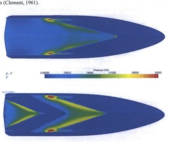
As mentioned in Chapter 1 and through results in Model 5631 model tests, reducing the wetted surface area is the driver to improve drag reduction. For the Dynaplane design, the idea of a fully ventilated afterbody is used. As shown in Figure 22, a stepped hull creates a ventilated region just aft of the step which reduces the drag. In the Dynaplane design, the surface piercing hydrofoils are the only appendages accounting for the wetted area on the afterbody. Enhancing performance through ventilation of a stepped planning hull has been accomplished in recent research (Brizzolara and Federici, 2013). Their design incorporated a transverse step with a high aspect ratio and swept back angles called a V-step design, shown in Figure 21.
In experimental results using CFD, a 19% drag reduction was achieved using the V-step. The comparison of the reduced wetted surface area and pressure distribution caused by the ventilation is shown in Figure 22. Clement's tow tank tests in the DTMB were able to achieve 10-15% drag reduction when comparing conventional and stepped planing hulls of various parametric variables (Clement, 1961).
Figure 22: Wetted Area and Pressure Distribution Comparison for Stepless and Stepped Hulls
Original Hull V-Step Hull
Drag [N]| 23,153 19,452
Trim [deg]| 2.76 4. 03
Table 2: Brizzolara and Federici's Drag Reduction Results
The evidence that using a stepped hull and partially or fully ventilating the afterbody is substantial. The Model 5631 Dynaplane design combines the drag reduction of a swept back, cambered step with a fully ventilated afterbody. Trim control must be maintained by a stem stabilizer; which Clement discusses in his paper. In the next chapter, the conversion of Model
5631 to a new Dynaplane configuration is covered in detail.
Rot"& (PC)
Chapter 3 - The Dynaplane Configuration
3.1 Clement's Dynaplane
The implementation of Eugene Clement's Dynaplane originates from its advantages of drag reduction (Clement, 1966). Furthermore, Clement discusses the performance predictions compared to a similar hull of lower deadrise, 12.5 degrees. The deep V hull has disadvantages dealing with its added resistance but it results in improved seakeeping. It also contributes to the reduction of vertical accelerations compared to a planing hull of shallower deadrise.
Stepped hulls begin to show their added benefit in Figure 4, which forms the basis for potential benefits of the Dynaplane design. There are several design options for a stepped hull including a traditional transverse step, multi-step, or a Dynaplane configuration. The traditional transverse step is a faired continuation of the bow shape yet it generally discontinues, or steps, aft of the center of gravity. The rest of the hull aft of the step is usually raised or angled to maintain proper ventilation. The Dynaplane configuration takes its name from its close relation to an airplane. It possesses a cambered step, resembling the bottom of an aircraft wing, which provides substantial lift at high speeds. It also creates a fully ventilated afterbody with maintaining trim control by using a stem stabilizer. Clement states, "A striking fact about the potential of the Dynaplane-type of stepped planing boat is that as the design speed increases, the hydrodynamic hull drag remains practically the same" (Clement, 2005). This thesis focuses on the improvement of the lift to drag ratio from the Dynaplane configuration and further improves on the options for an afterbody lifting surface.
In Clement's 2005 paper, design procedures are given based on a range of hull parameters. Specifically, he recommends choosing a hull with a deadrise no more than 15 degrees to achieve the best results. The Model 5631 Dynaplane design addresses the extension of Clement's design with respect to a 20 deadrise angle. The methodology of designing traditional airplanes closely resembles the design approach taken for the Dynaplane configuration because similar performance characteristics are desired such as producing sizeable lift with minimum drag, while remaining trim control and stability at high speeds. Clement's design procedures pay close attention to the lift and drag of the cambered surface. The longitudinal position of the cambered surface is dictated by the location of center of gravity. This becomes very important in the position of the afterbody lifting surface as well. Clement further recommends placing the center of gravity close to the mid-point of the planing hull length.
The Dynaplane design represents an improvement in powering requirements but it unfortunately introduces instabilities due to trim control deficiencies. This thesis addresses these instability issues at high speeds with the Dynaplane configuration, and attempts to provide a reasonable solution to not only predict but also solve instability at high speed. Clement discusses a limited range of applicability for this design. For example, the proposed afterbody lifting surface, or stem stabilizer has a limitation of 50mph or 43.4 knots. Later in this chapter, a newly designed surface piercing hydrofoil is introduced that can operate at cavitating speeds. This introduces unforeseen hydrodynamic considerations since the Model 5631 has a 20 degree deadrise and will operate at FnV = 5.
3.2 Cambered Step Design
Using the Model 5631 reference hull, a cambered step will be designed (Clement, 2005). Results from model tests discussed in Clement's paper determine that the main planing surface supports majority of the planing hull's weight. The goal of the Dynaplane's design is for the main cambered step to support 90% of the hull's weight, with the remaining 10% being provided by surface piercing hydrofoils. The angle of attack of the cambered step depends on the hull's speed, weight and location of the center of gravity. Therefore, Clement recommends choosing a trim angle at a specific design speed and appropriate for the deadrise of the hull. Since Model
5631 has a 20 degree deadrise, it was decided to select a running trim angle at the given design
speed of FnV = 5 (Metcalf et al, 2005). A resultant trim angle of 3.65 degrees was chosen from
the Metcalf et al paper, which matched the design speed prediction.
Following Celano's critical trim angle equation (Celano, 1998); it was found that the recommended trim angle for avoiding porpoising was 3.5 degrees. This smaller trim angle was derived for high speed planing craft in order to avoid porpoising. For this reason, two versions or generations of the cambered step was designed for possibly testing both designs. With a given trim angle, deadrise, and speed, the cambered step design can proceed. The procedure below will guide you through the design process of Gen 2's construction. With Model 5631 being selected, the trim angle, deadrise, speed, beam, and weight have now been chosen.
Trim Angle Deadrise FnV
Gen 2 3.5 deg 20 5
Table 3: Cambered Step Variant Generation Model 5631
Deadrise at transom deg
Table 4: Chosen Design Parameters for Dynaplane Configuration Design Procedure for a Cambered Planing Surface
1. Calculation of the lift coefficient for the cambered planing surface based on the beam and
weight of Model 5631:
0.9W 0.0474 C-'Lbp o.s p,-pV2b2
2. Selection of camber curve method on the step:
It is recommended to use the Johnson 3-term equation, which is a function of the lift coefficient desired. Johnson's equation for the curvature of the cambered step promises a 50% increase in the lift to drag ratio compared to a flat plate, shown in Figure 23. These surfaces were tested with a zero deadrise and aspect ratio (AR) of 2. From the results of using a Johnson 3-term camber profile, the design proceeded.
Y ( X2 - -20Xf + 80X - 64X7 -C 7.57r 1 1 L/D 8 6 4 20 Extrapolated 6 A 6 - experimental values -4 -DTMB calculations, ---
--Johnson 3-term cabe 3
Flat plate
(calculated)
calculated values and
extrapolated experimental
values are for a lift of 9000 lb and a beam of 6.2 ft, in salt voter at 590"
[
L [
I40=
0 0402 0.04 0.06 0.08 0.10 0.12 CLbFigure 23: Comparison of Calculated and Experimental Results of L/D for Johnson 3-Term Cambered Surface and a Flat Plate, AR = 2.0
3. Select value for deadrise angle. This is based on the Model 5631 reference hull. P = 20 degrees
4. Select ratios of tip chord to beam, It/b, and of root chord to beam, 1,/b:
lt/b
= 0.2 ; l/b = 0.85. Calculate aspect ratio, AR:
2
AR = 1 2
b b
An AR of 2 was chosen due to the majority of the experimental and theoretical results using the same value of AR. Thus, the relationship of the tip chord and root chord was chosen.
6. Select appropriate value for trim angle, -:
- = 3.5 degrees
7. Determine value of angle between the spray root line and the centerline:
tan tan = 14.79 degrees + 5 degrees = 19.79 der
For cambered surfaces, a five degree correction factor is added to the original value.
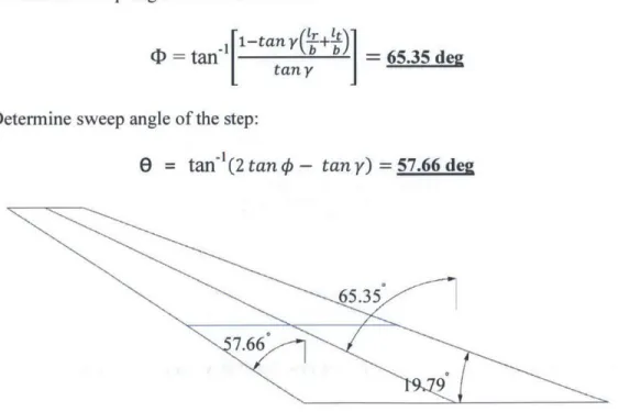
8. Figure 24 shows the plan view illustration of the proposed cambered planing surface. 9. Determine sweep angle of 50% chord line:
[1-tany
+t= tan'[ = 65.35 deg
tan y
10. Determine sweep angle of the step: