HAL Id: tel-01002037
https://tel.archives-ouvertes.fr/tel-01002037
Submitted on 5 Jun 2014HAL is a multi-disciplinary open access
archive for the deposit and dissemination of sci-entific research documents, whether they are pub-lished or not. The documents may come from teaching and research institutions in France or abroad, or from public or private research centers.
L’archive ouverte pluridisciplinaire HAL, est destinée au dépôt et à la diffusion de documents scientifiques de niveau recherche, publiés ou non, émanant des établissements d’enseignement et de recherche français ou étrangers, des laboratoires publics ou privés.
the air management of fuel cell systems
Dongdong Zhao
To cite this version:
Dongdong Zhao. Control of an ultrahigh speed centrifugal compressor for the air management of fuel cell systems. Other. Université de Technologie de Belfort-Montbeliard, 2013. English. �NNT : 2013BELF0220�. �tel-01002037�
University of Technology of Belfort-Montb´eliard (UTBM)
Doctoral School SPIM (Engineering Sciences and Microtechnology)
THESIS
Presented at
The University of Technology of Belfort-Montb´eliard for the degree of
DOCTOR OF PHILOSOPHY By
Dongdong ZHAO
Control of an Ultra-high Speed Centrifugal Compressor for the Air Management of Fuel Cell Systems
THESIS COMMITTEE:
M. Mohamed Benbouzid - Professeur, LBMS, Uniersit´e de Brest, Brest
M. Demba Diallo - Professeur, Universit´e Paris Sud-IUT de Cachan, Paris M. Bernard Davat - Professeur, GREEN, Universit´e de Lorraine, Nancy. M. Manfeng Dou - Professeur, Northwestern Polytechnical University, Chine M. Mahesh Krishnamurthy - Assistant professor, Illinois Institute of Technology, USA M. Abdellatif Miraoui - Professeur, UTBM
M. Fei Gao - Maˆıtre de conf´erences, UTBM
M. David Bouquain - Maˆıtre de conf´erences, UTBM
ABSTRACT
Fuel cell is a power supply system, which takes advantage of the electro-chemical reaction between oxygen and hydrogen to produce electricity with water as its byprod-uct. Due to their lower pollution and high efficiency compared with fossil fuels, fuel cell systems are under extensive development for many power applications. Compared with high temperature fuel cells (such as molten carbonate fuel cells or solid oxide fuel cells), the proton exchange membrane fuel cell (PEMFC) is more suitable for au-tomotive applications because of its low temperature working condition, thereby a fast startup.
Air compressor supplying the oxygen to the stack is an important component in the fuel cell systems. The compressor can consumes up to 20 % of the generated power in the most severe cases. The selecting of the compressor and corresponding control are directly related to the performance of the fuel cell. The size and weight of the air compressor has to be reduced to make them more feasible for automotive applications. Moreover, the control of the air compression system is also an important issue, which affects the efficiency and the safety of the fuel cell. To avoid oxygen starvation of the stack, the mass flow of the supplied air has to be controlled appropriately according to the load demand. Meanwhile, the pressure should not have large deviations or ripples which may damage the stack membrane.
In this thesis, the requirements to the compressor for fuel cell applications are dis-cussed. And several kinds of compressor are compared, including positive displace-ment types and dynamic superchargers. In the view of compactness, an ultra-high speed, up to 280,000 rpm, centrifugal compressor is adopted. The centrifugal com-pressor which is a kind of dynamics superchargers converts the kinetic energy of the air to the pressure. Compared with positive displacement compressors, it has the ad-vantages of compactness, high efficiency and low noise, making it more suitable for automotive applications. However, the difficulty of the control as well as the surge
constraint obstructs its industrial implementation for fuel cells.
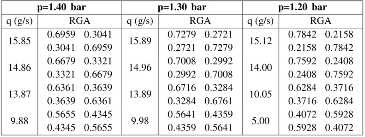
In this dissertation, The model of the air compression system is developed and the coupling between the model inputs and outputs are analyzed. The compressor map is measured and then fitted by a two hidden layer neural network model. The relative gain array (RGA) method is used for the coupling analysis. It shows that the coupling degree varies as the operation point changes because of the nonlinearity of the system. The second part of this work focuses on solving the control problems to adapt the cen-trifugal compressor to the fuel cell system. The objective is to control the mass flow and pressure simultaneously according to the fuel cell load demand. The problem lies in the coupling between the mass flow control and pressure control because the vari-ations of one variable will also lead to the deviation of the other one. The interaction between the two control loops declines the performance of the fuel cell system. Decou-pling controllers which aim to eliminate the interaction between the inputs and outputs are more feasible for the centrifugal compression system control. A recently proposed disturbance decoupling control (DDC) is used for the centrifugal compression system. DDC treats the internal interactions as a disturbance and then eliminates them in the control. The performance of the DDC is compared with a decentralized sliding mode controller. Through the comparison of those two controllers, the results show that the proposed DDC performs better in both the steady state and dynamic conditions, mak-ing the centrifugal compressor is capable of applymak-ing to the fuel cell in automotive applications. On a hardware-in-the-loop (HIL) testbench, the proposed controller is validated with a 10 kW fuel cell model under varied load demands. Moreover, a surge avoidance method, namely reference limiter, is proposed to prevent the compressor from surging. The experimental results show that the operation is restricted to the right of the surge line.
R ´
ESUM ´
E
La pile `a combustible est un syst`eme de production d’´energie, qui tire profit de la r´eaction chimique entre l’oxyg`ene et l’hydrog`ene pour produire de l’´electricit´e et de la chaleur tout en rejetant que de l’eau. En raison de leur pollution moindre par rapport aux carburants fossiles, les syst`emes pile `a combustible connaissent un d´eveloppement important pour de nombreuses applications de puissance. Par rapport aux piles `a com-bustible `a haute temp´erature (comme les piles `a comcom-bustible `a carbonates fondus et les piles `a combustible `a oxydes solides), la pile `a combustible `a membrane ´echangeuse de protons (PEMFC) est plus appropri´ee pour les applications automobiles en raison de sa temp´erature de fonctionnement plus faible et de son temps de d´emarrage plus rapide.
Le compresseur d’air alimentant en oxyg`ene la pile est un ´el´ement important dans les syst`emes pile `a combustible. Le compresseur peut consommer jusqu’`a 20 % de l’´electricit´e produite dans les cas les plus d´efavorables. Le choix et le dimension-nement du compresseur, ainsi que son syst`eme de contrˆole associ´e, sont directement li´es `a la performance du syst`eme global. La taille et le poids du syst`eme de compres-sion d’air doivent ˆetre r´eduits pour le rendre plus adapt´e aux applications automobiles. En outre, le contrˆole du syst`eme de compression d’air est ´egalement une probl´ematique importante car il affecte l’efficacit´e et la s´ecurit´e de fonctionnement de la pile `a com-bustible. Pour ´eviter une sous-alimentation en oxyg`ene de la pile, le d´ebit massique d’air fourni doit ˆetre g´er´e de fac¸on appropri´ee en fonction de la demande de la charge ´electrique. Pendant ce temps, la pression ne doit pas montrer de trop grandes variations ou ondulations qui peuvent endommager la membrane de la pile.
Dans ce m´emoire, les exigences pour le compresseur d’air pour des applications au-tomobiles sont pr´esent´ees et plusieurs types de compresseurs sont compar´es, y com-pris les compresseurs `a d´eplacement positif et dynamique. Le compresseur centrifuge ultra-rapide (280 000 tr/min), compte tenu de sa compacit´e et de ses performances,
a ´et´e retenu pour ces travaux. Le compresseur centrifuge, qui peut rentrer la famille des compresseurs dynamiques, convertit l’´energie cin´etique de l’air en pression. Par rapport aux compresseurs volum´etriques, il a les avantages de la compacit´e, une haute efficacit´e et un faible bruit. Cela le rend le plus adapt´e pour les applications automo-biles. Cependant, la complexit´e du contrˆole, due notamment `a la contrainte de la ligne de pompage, gˆene sa mise enœuvre industrielle dans les syst`emes pile `a combustible. Dans cette th`ese, un mod`ele du syst`eme de compression d’air est d´evelopp´eet le cou-plage entre les entr´ees et les sorties est analys´e. Le compresseur est caract´eris´e puis sa cartographie est ajust´ee par un r´eseau de neurones `a deux couches cach´ees. La m´ethode de la matrice de gain relatif (RGA) est utilis´ee pour l’analyse du couplage. Elle montre que le degr´e de couplage varie avec le point de fonctionnement, en raison de la non lin´earit´e du syst`eme.
Ce travail se concentre enfin sur la r´esolution des probl`emes de contrˆole pour adapter ce compresseur centrifuge au syst`eme pile `a combustible. L’objectif est de contrˆoler le d´ebit massique et la pression simultan´ement, en fonction des variations de la charge ´electrique. Le probl`eme r´eside dans le couplage entre la rgulation de d´ebit massique et la r´egulation de la pression. La variation de l’une des deux variables entraine une varia-tion de l’autre variable. L’interacvaria-tion entre les deux boucles de contrˆole diminue la per-formance du syst`eme. Comparativement aux contrˆoleurs d´ecentralis´es, les contrˆoleurs `a d´ecouplage qui visent `a ´eliminer l’interaction entre les entr´ees et les sorties sont plus adapt´es pour les syst`emes de compression centrifuges. Un contrˆole d´ecouplage propos´e r´ecemment dans la litt´erature, nomm´e contrˆole `a d´ecouplage de perturbation (DDC), est utilis´e pour le syst`eme de compression centrifuge. Le DDC traite les in-teractions internes comme une perturbation, puis les ´eliminent dans le contrˆole. Les performances du DDC sont compar´ees `a un dispositif de commande en mode glissant d´ecentralis´e. Grˆace `a la comparaison de ces deux contrˆoleurs, les r´esultats montrent que le DDC propos´e est performant tant pour des cas stables que dynamiques. Le com-presseur centrifuge est donc utilisable pour les syst`emes pile `a combustible automo-biles. Sur un banc d’essai hardware-in-the-loop (HIL), le contrˆoleur propos´e est valid´e avec un mod`ele de pile `a combustible de 10 kW avec des demandes de charge variables. En outre, une m´ethode d’´evitement d’instabilit´e, `a savoir un limiteur de r´ef´erence, est propos´e pour empˆecher le d´epassement de la ligne de pompage du compresseur. Les r´esultats exp´erimentaux montrent que, dans tous les cas, la zone d’utilisation du
com-vii
1. Introduction . . . 1
1.1 Proton exchange membrane fuel cell . . . 1
1.2 PEMFCs auxiliary components . . . 4
1.2.1 Fuel supply subsystem . . . 4
1.2.2 Humidification subsystem . . . 5
1.2.3 Cooling subsystem . . . 6
1.2.4 Power management subsystem . . . 6
1.2.5 Air management subsystem . . . 7
1.3 Compressor technology . . . 8
1.3.1 Positive displacement compressors . . . 9
1.3.2 Dynamic compressors . . . 10
1.3.3 Choice for PEM fuel cell system . . . 13
1.4 Research objective and scope . . . 18
1.4.1 Control problem overview . . . 18
1.4.2 Objectives and methods . . . 21
1.5 Thesis outline . . . 22
2. Air compression system modeling for PEMFC systems . . . 25
2.1 An ultra-high speed compressor . . . 25
2.2 Compressor modeling . . . 30
2.2.1 Compressor map modeling overview . . . 30
2.2.2 Compressor map measurement . . . 31
2.2.3 Neural network modeling . . . 33
2.3 Manifold modeling . . . 36
2.4 Actuators modeling . . . 39
2.5 Fuel cell stack model . . . 42
Table of Contents ix
3. Controller design and simulation . . . 47
3.1 Introduction . . . 47
3.2 Compressor coupling analysis . . . 49
3.3 Choice of the controller . . . 52
3.4 Disturbance decoupling control . . . 53
3.4.1 ADRC framework . . . 53
3.4.2 DDC approach . . . 54
3.4.3 ESO design for the air management system . . . 57
3.4.4 Control algorithm . . . 61
3.4.5 Simulation results . . . 63
3.5 Sliding mode control . . . 67
3.5.1 Pressure control . . . 68
3.5.2 Mass flow control . . . 70
3.6 Comparison by Simulations . . . 71
3.6.1 Test with mass flow variations . . . 72
3.6.2 Test with pressure variations . . . 75
3.6.3 Simulation with the parameter deviations . . . 77
3.7 Simulation for a 10 kW fuel cell model . . . 81
3.8 Conclusions . . . 86 4. Experimental results . . . 87 4.1 Experimental setup . . . 87 4.1.1 Signals measurement . . . 88 4.1.2 Real-time controller . . . 90 4.2 Surge prevention . . . 90
4.4 Applied to a 10 kW fuel cell model . . . 104
4.4.1 Oxygen excess ratio . . . 106
4.4.2 Pressure . . . 109
4.5 Conclusions . . . 111
5. Conclusions and future work . . . 113
5.1 Conclusions . . . 113
5.1.1 Compressor selection . . . 113
5.1.2 Proposed control approaches . . . 114
5.1.3 Applications . . . 115
5.2 Future work . . . 115
5.2.1 Active surge control . . . 115
5.2.2 Applied to an actual 10 kW fuel cell system . . . 116
5.2.3 Humidification control . . . 117
5.2.4 Cathode partial pressure observation . . . 119
LIST OF FIGURES
1 Fuel cell model. . . 3
2 A 5 kW commercial fuel cell stack consisting of 90 cells. . . 3
3 Fuel supply stream. . . 4
4 Schematic of fuel cell stack with internal humidifier [7]. . . 5
5 Air management system in the fuel cell system. . . 7
6 Compressor types. . . 8
7 Reciprocating compressors. . . 9
8 Reciprocating working characteristics. . . 10
9 Single rotor of an axial compressor [17]. . . 11
10 Dynamic compressor blades [22]. . . 12
11 Centrifugal compressor map. . . 12
12 Comparison between several kinds of compressor [16]. . . 13
13 Honeywell’s motorized compressor module [29]. . . 16
14 A 12 kW centrifugal compressor with maximum speed of 120,000 rpm [30]. 16 15 The prototype of an ultra-high speed centrifugal compressor for fuel cell systems. . . 17
16 Cross section view of the compressor. . . 26
17 Assembled rotor including impeller and high-speed ball bearings. . . 27
18 Critical speeds of the centrifugal compressor rotor. (Blue) No displace-ment. (Red) Maximal displacedisplace-ment. . . 28
19 Compressor maps. . . 29
20 Compressor efficiency map. . . 30
21 Measured compressor power. . . 32
22 Measured compressor map. . . 32
23 Neural network model of the centrifugal compressor. . . 34
24 Neural network layers. . . 35
25 The trained neural network model. . . 36
26 butterfly valve. . . 37
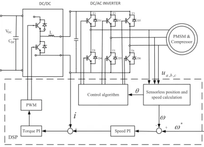
27 Pulse amplitude modulation (PAM) power electronics and control sys-tem for driving an ultra-high-speed PMSM. . . 39
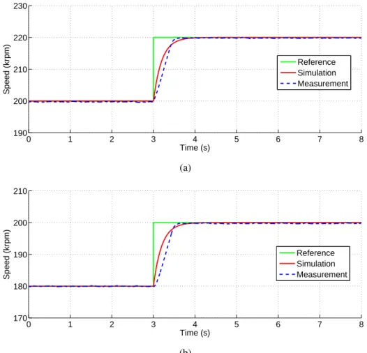
28 Comparison of the speed dynamics between the measurement and the simulation with Tm= 0.2. . . 40
29 Valve controller. . . 41
30 Valve position dynamics under the PI control. . . 41
31 Simulation and experimental results of the system. . . 45
32 Controllers for MIMO system. . . 48
33 Block diagram of the centrifugal compressor. . . 50
34 Compressor coupling analysis. . . 52
35 The i-th loop of the system. . . 55
36 Structure of the proposed ESO. . . 58
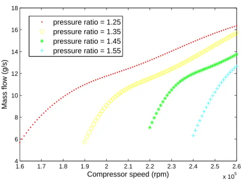
37 The relation of the mass flow and speed at different pressure ratio. . . 59
38 Mass flow estimation. . . 60
39 Pressure estimation. . . 60
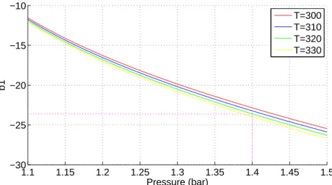
40 The relationship of b1with the pressure and temperature. . . 62
List of Figures xiii
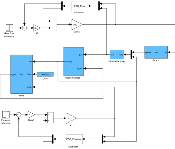
42 Simulation model in the Simulink. . . 64
43 Responses of the system under a mass flow step command. . . 65
44 Responses of the output variable under a pressure step command. . . . 66
45 Simulink model of the twisting algorithm. . . 69
46 Simulink model of the super-twisting algorithm. . . 70
47 Comparison of the DDC with the sliding mode controller with the mass flow variations. . . 73
48 Responses of the actuator under the mass flow variations. . . 74
49 Comparison of the DDC with the sliding mode controller with the pres-sure variations. . . 75
50 Responses of the compressor and valve. . . 76
51 Mass flow variations. (a) Mass flow dynamics (b) Zoom in of the mass flow deviation at 38 s. . . 78
52 Pressure variations. (a) pressure dynamics (b) Zoom in of the pressure deviations at 31 and 33 s. . . 79
53 Speed variations. . . 80
54 Valve position variations. . . 80
55 Fuel cell polarization curve (U−I) property. . . 81
56 Block diagram of the simulation. . . 82
57 Fuel cell current. . . 82
58 Mass flow. . . 83
59 Oxygen excess ratio. . . 83
60 Pressure. . . 84
61 Compressor speed. . . 84
62 Valve position. . . 85
64 Hardware-in-the-loop air management test bench. . . 87
65 Temperature sensor (right) and pressure sensor (left). . . 88
66 Valve position measurement. . . 89
67 Mass flow sensor. . . 89
68 DS1104 controller board layout. . . 91
69 Testbench block diagram and connections. . . 91
70 The trajectory of the compressor operation. . . 93
71 Oscillations caused by the reference limiter in terms of equation (4.1) and (4.2). . . 95
72 Surge prevention as the results of the improved reference limiter. . . 96
73 Comparison by hard-ware-in-the-loop test. . . 97
74 The responses of the mass flow and pressure under a mass flow step command. . . 98
75 Measurement at steady state (zoom-in of Figure 74). . . 99
76 The actuator responses under a mass flow step-up. . . 100
77 The responses of the mass flow and pressure under a pressure step command. . . 101
78 Zoom in of Figure 77. . . 102
79 The actuator responses. . . 103
80 Block diagram of the fuel cell stack model. . . 105
81 Current drawn from the fuel cell stack. . . 105
82 Calculated mass flow reference and the measurement in real time. . . 107
83 Oxygen excess ratio. . . 107
84 Compressor speed dynamics during the operation. . . 108
List of Figures xv
86 Supplied air pressure. . . 109
87 Realtime simulated fuel cell stack output voltage. . . 110
88 Realtime simulated fuel cell stack output power. . . 110
89 Operating range of surge avoidance and active control. . . 116
90 A 10 kW fuel cell system testbench. . . 117
91 Membrane specific resistance vs. average water content at 80oC and with the same water activity at the anode and cathode side [10]. . . . 118
92 Saturated vapor pressure at different temperature. . . 118
93 Fuel cell current variations. . . 122
94 Compressor mass flow variations. . . 122
95 (a) Cathode pressure estimation, (b) Zoom of the startup. . . 123
96 (a) Supply manifold pressure estimation, (b) Zoom of the startup. . . . 124
97 (a) Oxygen partial pressure estimation, (b) Nitrogen partial pressure estimation. . . 125
LIST OF TABLES
1 Specifications of the PMSM. . . 27 2 Thermodynamic constants and manifold parameters. . . 38 3 Fuel cell stack parameters. . . 43 4 The RGA of the centrifugal compressor at different operating points. . 51 5 Parameter deviation range. . . 77 6 Characters of the sensors. . . 90 7 Operating conditions of the PEM fuel cell stack. . . 104
1. INTRODUCTION
1.1
Proton exchange membrane fuel cell
Nowadays, the research on alternative/renewable energy sources have received more and more attention resulting from the increasing energy consumption. Fuel cell sys-tems, which take advantage of the electro-chemical reaction of fuel gases to produce electricity with water and heat as the byproduct, are promising power supply equip-ments because of their high efficiencies and low pollutions. Nowadays fuel cell sys-tems are under intensive development in terms of the cell material and auxiliary de-vices, which promote both the stationary and automotive applications. Compared with traditional heat engines, fuel cells have high power density and greater efficiency, as high as 60 % in electrical energy conversion and overall 80 % in co-generation of elec-trical and thermal energies [1]. Unlike batteries with the reactants stored internally, the reactants of fuel cell are stored externally, which can make it operate continuously as fuel is available.
Five categories of fuel cells have received major efforts of research [2]:
1. Proton exchange membrane fuel cells (PEMFCs): The PEMFCs use solid poly-mer electrolytes to exchange the ions between two porous electrodes, which is a conductor of protons and an insulator for electrons. Low temperature PEMFCs operate around 70◦C. Whereas, the working condition is up to 180◦C for high temperature PEMFCs. The advantages of PEMFC are their high power density and fast star-up which make it suitable for automotive applications.
2. Alkaline fuel cells (AFCs): The AFC uses an aqueous solution of the potassim hydroxide as an electrolyte. AFCs operate at a low temperature around 100◦C and it has the high efficiency up to 60-70 %. However, they are sensitive to CO2
because it consumes the alkaline in the electrolyte thereby reducing the concen-tration of hydroxide ion during chemical reactions. Therefore, they need a sepa-rate system to remove the CO2from the air. The use of a corrosive electrolyte is also a disadvantage because it has shorter life span [2].
3. Phosphoric acid fuel cells (PAFCs): PAFCs are a type of fuel cell that uses liquid phosphoric acid as an electrolyte. They are the first commercialized fuel cells. Unlike PEMFCs and AFCs, they are very tolerant to impurities in the reformed hydrocarbon fuels. They operate about 175-200◦C. And their efficiency could be up to 70 %. They are typically used for stationary power generation.
4. Solid oxide fuel cells (SOFCs): The SOFCs which operate around 1000◦C with an electrical efficiency of around 50%. They use dense yttria stabilized zirconia, which is a solid ceramic material, as the electrolyte. SOFCs have high efficiency of 50-60 %. Whereas, they need a long start-up time because of the high temper-ature. SOFCs are mainly used for stationary applications in medium and large power capacity.
5. Molten carbonate fuel cells (MCFCs): MCFCs working around 650◦C is a kind of high temperature fuel cell. Unlike low temperature fuel cells, MCFCs do not need expensive metal as the fuel catalyst. It has two porous electrodes with good conductivity are in contact with a molten carbonate electrolyte. Like SOFCs, MCFCs also has the disadvantage of slow star-up.
Among different types of fuel cells, the PEMFCs show more advantages for transporta-tion applicatransporta-tions because of their low temperature working conditransporta-tions, fast start-up and good dynamic characteristics. Interests in fuel cell can be traced back to the late 1970s and received a major boost in recent years. Many motor corporations have been de-veloped even released their fuel-cell vehicles based on PEMFC, e.g. GM Hydrogen 1, Honda FCX-V3, Toyota FCHV, etc [1].
The basic working principle of a PEMFC is shown in Figure 1. A single cell consists of seven elementary layers: The cathode gas channel which is used to circulate the air, the cathode gas diffusion layer where water and oxygen diffuse, the cathode cat-alyst layer where the oxygen is consumed and the water is produced, the membrane where allowing protons to pass through while blocking electrons, the anode catalyst
1.1. Proton exchange membrane fuel cell 3
layer where hydrogen is consumed, the anode gas diffusion layer where hydrogen and water diffuse, and the anode gas channel which is used to circulate the hydrogen. A commercial fuel cell (Figure 2) consists of a number of single cells depending on the power capacity.
Cathode catalyst layer Membrane
Cathode gas diffusion layer
Anode catalyst layer Anode gas diffusion layer Air Hydrogen 2 2H 4H4e 2 4 4 O e H 2 2H O H V e e Cathode gas
channel Anode gas
channel
Fig. 1. Fuel cell model.
1.2
PEMFCs auxiliary components
1.2.1 Fuel supply subsystem
In the operation of a fuel cell, the fuel (hydrogen) has to be provided continuously to the anode side. Normally, there are two kinds of fuel supply methods as shown in Figure 3: One is that store the pressurized pure hydrogen in a tank and transport it directly to the fuel cell stack; The other way is by reforming available fuels such as methanol, gasoline, natural gas, etc., to produce hydrogen on site, and then supply it to the fuel cell. For most of vehicular applications, the first method is adopted because of its high purity and reliability. Whereas, the second method has been used for many stationary power units.
Several kinds of fuel generation strategy have been studied over the past few years [3– 5]. The presence of CO in the reformate are well known contributors to the failure of the PEM stack, and thus its need to be constrained to very low concentrations. For example, the maximum allowable CO concentration in the reformate is typically as low as 50 ppm by volume or less [4, 5]. To remove (reduce) the CO, the air is needed to injected to the reformer, and then reacts with CO.
Hydrogen tank Fuel cell
Methanol/Gasoline/
Natural gas/... Fuel reformer Water Fuel cell 2 H 2 H Pressure reducer Valve Fuel processor
b. Hydrogen is produced on site
a. Hydrogen is stored in a high pressure tank
Catalyst Air
1.2. PEMFCs auxiliary components 5
1.2.2 Humidification subsystem
Maintaining proper membrane humidity is one of the key requirements for the fuel cell to reach its optimum performance. The intention of humidification of the gases enter-ing the fuel cell is to maintain proton conductivity of the electrolyte in the membrane. Without humidification, the membrane becomes too dry and thus prohibits the proton transport. Therefore it results in poor fuel cell function or even failure.
Two kinds of humidifying methods exist, namely, external humidification and inter-nal humidification. The interinter-nal humidification, shown in Figure 4, is based on the principle that the electrolyte absorbs and retains water under the operating conditions by introducing a special membrane [6]. Porous membrane located between the gas channel and the water channel is used to transfer the water vapor [7]. Water droplets permeate through the membrane from the water side to the gas side. The heat produced in the stack could be used as an energy source for vaporizing water in this method.
Fig. 4. Schematic of fuel cell stack with internal humidifier [7].
The external humidification methods such as bubble humidifiers, enthalpy wheel ex-changer, direct water vapor injection into the reactant gases, lead to additional energy consumption [8]. In this way, an auxiliary component, humidifier, is needed. Humid-ifiers provide heat and humidity to the incoming oxidant or hydrogen fuel stream of fuel cells and are critical to overall system performance and reliability. The external
humidification method is widely used in small scale laboratory fuel cell experiments due to its simplicity [9].
1.2.3 Cooling subsystem
During the operation of PEMFCs, large amount of heat is generated which should be effectively removed to avoid overheating of the membrane and other components. The favorable working temperature of PEMFCs is usually between 60◦C and 80◦C. A high temperature can significantly exacerbate the degradation of the membrane and the catalyst, and reduce the stack performance, while a lower temperature is not favorable for the reaction kinetics and may also cause flooding due to lower water saturation pressures at low temperatures [10].
Several cooling methods have been studied, such as using highly thermal conductive material as heat spreaders, air flow cooling, liquid cooling, etc. Both increased supply of cathode air and additional air channels have been studied as the air cooling. The liq-uid cooling method, in which additional devices are needed, has been widely employed for automotive applications because of its strong cooling capability.
1.2.4 Power management subsystem
For hybrid vehicles, where the fuel cell combines with energy storage devices, such as batteries and ultra-capacitors to output energy, power management strategy affects the vehicle performance and efficiency significantly. Several topology connections and control strategies have been developed to optimize the energy consumption [11–15]. The energy flow which is determined by the power management method is controlled by DC/DC converters. Because of the dynamics of the load, the fuel cell alone might cannot satisfy the load demand resulting from its slow response. A energy storage devices such as batteries and ultra-capacitors can be used to absorb the fast transient. The fuel cell output power is delivered to the load through a uni-directional converter. Whereas, a bi-directional converter is used to transfer the energy to/from of the storage devices, e.i. charge or discharge.
1.2. PEMFCs auxiliary components 7
1.2.5 Air management subsystem
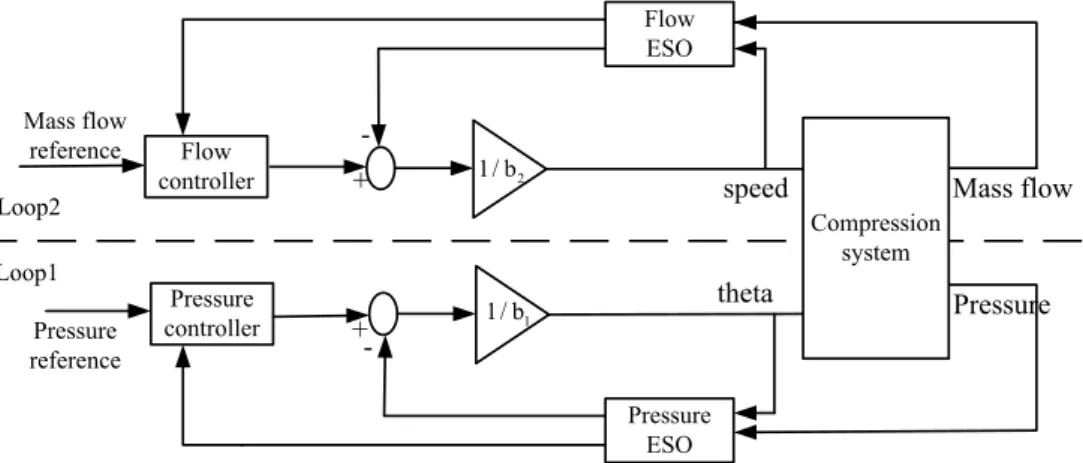
Air management subsystem (AMS) is used to supply the compressed air to the fuel cell cathode, where the electro-chemical reaction takes place, producing the electricity with the water and heat as byproducts. The block diagram of the AMS is shown in Figure 5. Cathode Compressor Controller Filter Air humidifier air Pressure, Mass flow Current
Inverter Valve control
valve Anode humidifier Membrane Motor Sensors Sensor
Fig. 5. Air management system in the fuel cell system.
The major tasks of the air management subsystem are as follows [16]
• Air supply. The air management system has to supply sufficient reactant flow to keep the desired oxygen excess ratio over the full power range. Insufficient air flow may damage the stack in severe cases. The air is normally circulated by a air compressor or blower.
• Air cleaning. Any particle or chemical substance, such as carbon monoxide, can be harmful for the catalyst and the membrane. Therefore, the air has to be filtered before going into the stack.
• Air pressurization. The air supplied to the fuel cell is generally pressurized from slightly above atmospheric pressure to 2.5 bar, depending on the stack require-ment. Pressurizing the air to the fuel cell implies a high efficiency and gives better water balance characteristics. Higher air pressure implies a more compact
stack and higher power density. Whereas, compared with low pressure fuel cells, more parasitic power losses are produced by the air compressor.
• Air humidification. The polymer membrane has to be maintained in a fully hy-drated state to have optimal working conditions. The air management subsystem usually combines the humidification subsystem to fulfill this target.
In order to fulfill these tasks, many components are needed. For the cleaning of air, filters are needed to remove particles before the air going into the fuel cell. The air transportation and pressurization could be realized by an air compressor or blower. Meanwhile, a control system with sensors is needed to control the mass flow and pres-sure properly to enpres-sure good transient responses of the fuel cell.
1.3
Compressor technology
The air compressor, the key component of the AMS, is the largest parasitic power consumption device in the fuel cell system. In the most severe cases, it consumes up to 20 % of the generated power. The compressor efficiency including motor, power converter, and controller depends on the compressor type, the pressure level, and the speed. According to the working principle, a general classification of the compressor is depicted in Figure 6.
Compressor Types
Positive Displacement Dynamic
Centrifugal Axial
Reciprocating Rotary
Single-Acting Double-Acting Lobe Diaphragm
Screw
Vane Scroll
1.3. Compressor technology 9
Several kinds of compressor, including positive displacement compressors (scroll, screw, lobe, centrifugal, etc,) and dynamic compressors like centrifugal type, have been stud-ied for fuel cell applications in the literature.
1.3.1 Positive displacement compressors
Positive displacement machines (Figure 7) work on the principle that: changing the pressure by mechanically changing the volume of the working fluid. They typically operate in two different ways: reciprocating and rotary.
Intake Discharge
Fig. 7. Reciprocating compressors.
• Reciprocating. Reciprocating compressors, also known as piston compressors, compress the fluid by reciprocating motion of a piston within a cylinder. The overall cycle is charactered by four typical phases of intake, compression, dis-charge, and expansion shown in Figure 8. As the piston moves downward, a vac-uum created, the intake valve is forced open and fluid is sucked into the cylinder. After the piston reaches its bottom position it begins to move upward. The intake valve closes and the pressure increases inside the cylinder. At a certain point the pressure exerted by the fluid forces the exhaust valve to open and the compressed fluid flows out of the cylinder. Once the piston reaches it top-most position, it starts moving downward again and the cycle is repeated. These pumps can be
single-acting, meaning they operate via single or independent discharge and suc-tion strokes. They can also be double-acting, meaning they create discharge and suction in both directions.
Volume Pressure Intake Compression Discharge Expansion
Fig. 8. Reciprocating working characteristics.
• Rotary. Rotary compressors work by changing the fluid volume by the rotating action. A rotary compressor consists of a rotor inside a cylinder, spring-mounted blades and a stator. The rotor rotes around a shaft with a variable volume of fluid. At a certain point in the rotation, a quantity of fluid is sucked into the cylinder and kept in a sealed area. The pressure increases as the volume becomes smaller by the rotating action. When reaching sufficient-high point, the gas pressure forces the exhaust valve to open and then the fluid is released. With the rotating going on anther operation of compressing begins. Rotary compressors have the same working principle with the reciprocating machines: having four operation stages: expansion, intake, compression and intake.
1.3.2 Dynamic compressors
Dynamic compressors compress air work by mechanically changing the velocity of the working fluid. Unlike positive displacement compressors, they can supply continues air flow. According to the flow direction they are divided into axial and centrifugal types.
1.3. Compressor technology 11
• Axial. An axial compressors has a rotor with rows of blades which accelerate the velocity of the flow. Figure 9 shows the single rotor of an axial compressor [17]. The stator is composed of many fixed blades which is used to guide the direction of flow and increase the pressure. The flow both enters and exits the compressor in an axial direction, parallel with the axis of rotation. In an axial flow compressor, multi-stage, successive rotor-stator pairs, are generally used to raise the pressure.
Fig. 9. Single rotor of an axial compressor [17].
• Centrifugal. Like axial compressors, centrifugal compressors realize compres-sion by transferring momentum to the fluid and the subsequent diffucompres-sion to con-vert the kinetic energy into pressure . The momentum transfer takes place at the doubly curved blades of the impeller that is mounted on a rotating shaft. Diffu-sion takes place in the annular channel of increasing radius around the impeller, usually referred as the diffuser [18]. Whereas, unlike axial compressors, cen-trifugal compressors change the direction of the fluid from parallel to vertical orientation of the rotor as shown in Figure 10. Mechanical and thermodynamic modeling of the centrifugal compressor are available in [19–22]. External char-acteristics of a centrifugal compressor can be described by its speed, mass flow, pressure and efficiency. A typical centrifugal compressor map is shown in Fig-ure 11, which depicts the relation of the speed, mass flow and pressFig-ure.
Dynamic compressors usually require high speed to increase the momentum of the fluid. Therefore, they are more compact than positive displacement com-pressors. Dynamic compressors are more efficient, especially operating at full
power. The working principle makes that positive displacement compressors, unlike dynamic compressors, cannot supply continue flow. An comprehensive comparison of these compressors are depicted by radar diagrams in Figure 12.
(a) Centrifugal compressor (b) Axial compressor
Fig. 10. Dynamic compressor blades [22].
1.3. Compressor technology 13
(a) Compressor types
(a)Centrifugal (b)Claw (c)Lobe (d)Membrane (e)Piston (f)Rotary vane
(g)Screw (h)Scroll (i)Side channel
(b) Comparisions
Fig. 12. Comparison between several kinds of compressor [16].
1.3.3 Choice for PEM fuel cell system
Fuel cell performances greatly relate to the compressor behavior. The compressor needs to be appropriately chosen according to the requirement of the fuel cell system. For automotive applications, following requirements need to be considered [16].
• Oil free. Oil which is pernicious for the fuel cell membrane is not allowed in the air flow. The oil-free air compressor should be used for fuel cell applica-tions. For positive displacement compression technology, even so called
”oil-free” machines use oil lubricants that migrate into and contaminate the gas path. In contrast centrifugal compressors have distinct advantage of being an oil-free air compressing system.
• Low parasitic consumption (high efficiency). Air compression system which can consumes up to 15 % of the fuel cell generated power is the biggest parasitic losses. A high efficiency compressor reduces the parasitic power losses and therefore increases the overall system efficiency. Centrifugal compressors could achieve higher efficiency since less friction losses are produced.
• Compactness. For automotive applications, the volume and weight of the fuel cell system have to be reduced. It also applies to the air compressor. In terms of compactness, the centrifugal compressor which usually operates at high speed is superior to positive displacement compressors.
• Flexible flow operation. Fuel cell vehicles need the fuel cell to work around an optimized operating range according to the load demand. Therefore, varied current drawn from the fuel cell requires the compressor to supply a flexible flow rate. Therefore, a fast mass flow controller is necessary in order to make the fuel cell work efficiently. The mass flow of positive displacement compressors is directly related to the compressor speed. Whereas, the centrifugal compressor’s flow is affected by not only the speed but also the pressure. In other words, more efforts has to be made to control a centrifugal compressor for fuel cell applications.
• Low noise. In automotive applications, especially for vehicles, the noise is also a performance index. Generally, rotary compressors have lower noise than the reciprocating compressors.
• Small pressure ripple. For the stack, large pressure ripples may damage the thin polymer-membrane and produce voltage pulsation, which should be avoided. Positive displacement compressors normally work on an constant pressure. There-fore the cathode pressure changes when the mass flow changes. Centrifugal com-pressor can work on different pressure point controlled by the speed and mass flow.
1.3. Compressor technology 15
Many research and development efforts are aimed at different compressor technolo-gies and their possible implementation in fuel cell systems [23]. In 1999, Air Squared designed the first scroll fuel cell compressor with the maximum pressure of 1.38 barg, and maximum mass flow of 28 g/s [24]. It can be driven by a 2.5 kW brushless DC motor or an induction motor. For automotive applications, a 2.2 kW scroll compressor driven by a induction motor using senorless technology has been studied in [25]. The nominal pressure is kept at 2.0 bars. And a simplified fuel cell model is used to vali-date the proposed method under Classic European Driving Cycles. In [26], a three-lobe compressor driven by an induction motor was modeled and analyzed for the possible application in the fuel cell system. This compressor has the maximum mass flow of 20 g/s with the maximum pressure of 2.0 bars. However no fuel cell character was described in the literature. A three-order fuel cell model driven by a twin-screw com-pressor has been developed in [27] and it is controlled by a sliding mode controller. The proposed air supply system is used to feed in parallel two PEM fuel cell stacks of 20 kW each. However, in the system the pressure issue which is an important variable was not discussed. A 860 W rotary vane compressor driven by a brushless DC motor has been used in Fclab, France [28]. The maximum mass flow is 15 g/s and maximum absolute outlet pressure 1.5 bars. This compressor is validated on a 5 kW PEM fuel cell plant.
All the compressors mentioned above are positive displacement machines.The United States department of Energy (DOE) gave the technical challenges and objectives of air compression system for a 80 kW transportation fuel cell systems. The technical plan, according to the 2017 target, shows that the weight has to be reduced from 22 to 15 kg. Meanwhile the durability is planed to 5000 h and efficiency to 75 %. The motor and controller efficiency at full flow is 90 %. It is 80 % at 25 % flow. It is well known that compared with other displacement compressors, centrifugal compressors have the advantages of compactness and high efficiency. They are more suitable to fulfill those targets. Under contract to the DOE, Honeywell has designed the motor-driven centrifu-gal compressor/expander and evaluated data on its performance, weight, and projected cost. Fulfilling the 2010 target of DOE, a Honeywell’s compressor for a 80 kW fuel cell is shown in Figure 13 [29]. It has the maximum shaft speed of 110,000 rpm, with a minimum idling speed of 36,000 rpm required by the bearings. To fulfill compactness requirement, Miti Ltd also developed a centrifugal compressor (Figure 14) driven by permanent magnet motor, for fuel cell applications [30]. This compressor can operate
from 20,000 to 120,000 rpm to meet pressure and flow demands.
Fig. 13. Honeywell’s motorized compressor module [29].
flow
Figure 1. MiTi® Fuel Cell Compressor/Expander
Fig. 14. A 12 kW centrifugal compressor with maximum speed of 120,000 rpm [30].
In general, positive displacement compressors which has a fixed internal pressure ratio, on the other hand, offer more flexible pressure ratio at low mass flow rate because they don’t suffer surge phenomenon. Therefore, they can operate at the expected pressure ratio which is desired by the fuel cell. Moreover, the air flow and pressure can be con-trolled decoupled, and thereby it simplifies the controller design. However, the bulki-ness and discrete output flow of the positive displacement compressors are the crucial disadvantages for automotive applications. The centrifugal technology has major ad-vantages of compactness, low noise and high efficiency, which make it more suitable
1.3. Compressor technology 17
for automotive applications. For automotive compactness requirement, in this dis-sertation, an ultra-high speed centrifugal compressor (maximum speed 280,000 rpm) is adopted. The prototype of the compressor is shown in Figure 15. In addition to the merits of a centrifugal compressor, the adoption of ultra-high speed technology in compressor design results in the ultra-compactness. The advantage of this high rota-tional speed is the decrease of the impeller radius and therefore an increase in power density in turbo machinery [31]. Also the electrical motor power density is roughly proportional to the speed.
Fig. 15. The prototype of an ultra-high speed centrifugal compressor for fuel cell systems.
In summary, the centrifugal compressor exhibits more benefits for automotive fuel cell applications. However, the control problems, such as pressure control and surge control, introduced by the centrifugal compressor have to be solved. Moreover, the fuel cell characteristics and load situations have also to be considered in the controller development. Therefore, new control technologies are needed to cope with the control problems to satisfy the demands from both the compressor and the fuel cell. In fact, recently many control methods have been proposed to deal with the air management problem of fuel cell systems. More details are discussed in the following section.
1.4
Research objective and scope
1.4.1 Control problem overview
In transportation applications, because of the dynamic load characteristic, the fuel cell needs to work at different operating points. During transients, current is instanta-neously drawn from the load source connected to the fuel cell stack. An air man-agement system is needed to provide sufficient oxygen for the fuel cell and regulate the pressure to a proper value to make fuel cell work at its optimal efficiency. A great deal of equipments (see Figure 5) are needed to fulfill these tasks. Explicit descriptions of the AMS and the tasks of each component were presented in [16].
Both the supplied air flow rate and pressure ratio need to be controlled appropriately in the operation of a fuel cell system. Insufficient air flow will probably lead to the oxygen starvation, which is a dangerous situation for the fuel cell stack. Whereas excessive parasitic power will be consumed if over flow rate is supplied. The supplied air pressure has a significant influence to the output voltage and efficiency of the fuel cell system. Moreover, the safety of the fuel cell stack depends much on a stable air pressure delivery. No pressure ripple greater than 100-200 mbars is allowed for automotive applications. A greater pressure ripple would damage the membrane. Fuel cell oxygen starvation, which indicates insufficient oxygen is supplied to the fuel cell, is an undesirable phenomenon. In order to avoid oxygen starvation a fast response of mass flow rate is necessary. In [32], a PI controller with feedforward method was used to control the fuel cell breathing. It shows that an appropriate feedforward com-ponent can effectively improve the mass flow response. Both static feedforward and dynamic feedforward are studied. The oxygen excess ratio was maintained at 2. This control is realized by linearizing the fuel cell at nominal operating point. However, because of the highly nonlinearity of the fuel cell system, the traditional PI control is not qualified. Some advanced control approaches have been proposed for the air cir-cuit control in the past few years [33–36]. In [37–39], model predictive control (MPC) methods, including nonlinear MPC, explicit MPC and constraint MPC, were studied for the air feed of a fuel cell. Those paper are focused only on maintaining the oxy-gen excess ratio in a desired value by controlling the compressor voltage. [35] use the MPC to fulfill multi control targets including the pressure, excess ratio and current.
1.4. Research objective and scope 19
However, it did not dig into the air flow control. Both the mass flow controller and electrical load are modeled as a first-order lag element. The advantage of MPC is that it can deal with the system constraints, such as the oxygen excess ratio and input volt-age. However, MPC needs an accurate system model which is very difficult to obtain for fuel cell system. Moreover, it is very sensitive to system parameters and external disturbances, therefore is has a reduced robustness. And the heavy computation load is also a disadvantage of MPC.
Sliding mode control was also studied for the air flow control in fuel cell systems [27, 40–42]. In [40], a sliding model control with feedforward is used to track the reference of oxygen excess ratio. And variable setting of the reference was proposed according to the load current in order to obtain the maximum efficiency. A rate limiter in the slop of the compressor signal was implemented to avoid the compressor stalling. A reduced-order fuel cell model and a sliding model controlled motor-compressor was experimentally validated in [27]. In this reference, a four-order and three-order fuel cell model was developed respectively. And the compressor is modeled as a first-order sys-tem, controlled by the quadratic current component. Based on this model, sub-optimal second order sliding model control and super-twisting sliding mode control were de-veloped in [43]. For those literature mentioned above, the sliding mode controllers were developed based on single input single output controlled strategy. They are fo-cused only on the flow rate control or oxygen excess ratio control. The air pressure which is very a crucial variable in the fuel cell system was not taken into considera-tion. Moreover, sliding mode controller development also needs an explicit model. Fuzzy logic was also studied to control the mass flow and pressure using the compres-sor speed and valve position respectively in [44]. A three-lobe comprescompres-sor was used and all the control parameters were obtained by experimental tests. Some other ad-vance controllers, such as adaptive method, robust approach and flatness-based control were also proposed by recent research [34, 45, 46] for fuel cell air breathing manage-ment. However, the compressor parameters and corresponding control were not de-tailed. In this research, we focus on the air compressor control to supply appropriately the flow rate and pressure into the fuel cell.
This work realize the air management of a fuel cell system by controlling a centrifu-gal compressor. The control of a centrifucentrifu-gal compressor is challenging because of the strong coupling between its pressure and mass flow. The main difficulties for
cen-trifugal compressor applications are pressure control and surge avoidance. Unlike dis-placement compressors, pressure control is challenging for centrifugal compressor as it is strongly coupled with the mass flow control. The mass flow has to be promptly regulated according to the load situations, which greatly varies the pressure ratio if it is not adjusted in time. In severe cases, the pressure may be dragged out of the normal operating region, which will paralyze the whole system. The highly nonlinear charac-teristic of mass flow, pressure, and speed also adds to the difficulty of pressure control. For the stack, large pressure ripples may damage the membrane and produce voltage pulsation, which should be avoided. In this work, a discharge valve is employed to control the pressure ratio.
For transportation applications of a fuel cell system, because of the load variations, the supplied mass flow has to be regulated accordingly to avoid fuel cell starvation [32]. Meanwhile, the air pressure also need to be controlled in order to achieve optimal power output. Large pressure ripples may shorten the stack life time and damage the fuel cell membrane in severe cases. Therefore, the pressure and mass flow control are crucial in operating of a fuel cell system. The control of a centrifugal compressor for fuel cell applications has been studied in [41, 47, 48], where the only control variable is the motor input voltage, which cannot control the pressure and mass flow simultane-ously. In [49, 50], A PI controller and a sliding mode controller have been developed respectively to control the mass flow and pressure simultaneously. However, the cou-pling problem, which is a significant problem in the control of a centrifugal compres-sor, was not addressed. Therefore, the interaction between the air flow and pressure can reduce the control performance, therefore degrade the fuel cell performance.
For the implementation of a centrifugal compressor in a fuel cell system, surge con-straint has to be considered to avoided the compressor surge. In [47, 48, 51, 52], ref-erence/load governor approaches were proposed to restrict the current drawn from the fuel cell. Therefore the mass flow reference is changed according to the load governor. Then the compressor constraints, such as the surge and chock constraints, are fulfilled. This approach depends much on the power management system and the hybrid fuel cell configuration. In those literature, they supposed that the fuel cell current can be ideally distributed. Those reference governor were based on different control laws, such as robust and MPC approaches. But the computation is time consuming.
1.4. Research objective and scope 21
1.4.2 Objectives and methods
1. Mass flow and pressure control. The air flow and pressure directly decide the output power of the fuel cell and have a great influence to the fuel cell safety. To control the mass flow and pressure simultaneously according to the load demand is the main research of this dissertation. The coupling degree of the centrifu-gal air compression system is analyzed by relative gain array (RGA) method. And the proper control pairs are determined for the two-input two-output system becoming a two-control-loop system. Two controllers, sliding mode controller and disturbance decoupling controller (DDC), are developed. The sliding mode controller regulates the mass flow and pressure independently through two de-coupled control loops. However, because of the interaction the mass flow and pressure influence each other greatly especially during transient. Therefore a decoupling controller is necessary for this multivariable system.
Traditional model-based decoupling control technologies are not feasible for the centrifugal compression system because of the system’s highly nonlinearity as well as the complexity of its mathematical model. In this paper, the dynamic dis-turbance decoupling control, which is derived from active disdis-turbance rejection control (ADRC), is first implemented for the centrifugal compression system. ADRC, which is a drastic departure from both the PID and the model-based mul-tivariable control paradigms, is a relatively new control design concept and a nat-ural fit for strong coupling system [53–57]. The idea is that, the couplings among various channels are estimated and canceled in real time based on the measured input-output data, reducing the complicated multivariable control problem to a set of independent control loops [58]. Consequently, the control system can react promptly to the changes either in the internal dynamics of the plant, or its exter-nal disturbances. Such materialization of ADRC in multivariable control setting is denoted as dynamic disturbance decoupling control (DDC) in [59, 60]. In this dissertation, a recently proposed dynamic DDC approach [59] is applied to the centrifugal compression system. Unlike many existing decoupling methods, the new method requires very little information of the plant dynamic. The essential information needed for the controller design is obtained not from a mathematical model but through the input-output data of the plant in real time.
peak head capability and minimum flow limit are reached. The compressor loses the ability to maintain the peak head when surge occurs and the entire system becomes unstable [61]. Surge is an unstable state, which gives rise to oscillations of mass flow and pressure ratio, and severely reduces compressor efficiency. Moreover, it can possibly damage the compressor in the most severe cases [62]. An effective and direct way to deal with the surge constraint is to make the compressor operate to the right of the surge line. In this dissertation, a reference limiter is designed to cope with the surge constraint. This reference limiter is a simple method to suppress the fast increase of the pressure by reconstructing its references. Then, the trajectory of the operation is controlled to the right of the surge line, thereby avoidance of the surge phenomenon.
1.5
Thesis outline
This dissertation is divided into five chapters. The current chapter has presented the compressor technologies for the air management of fuel cell systems. The require-ments to the compressor for automotive applications has been discussed, such as com-pactness, low noise, oil free, etc.. Based on those requirements, an ultra-high speed, resulting in ultra-compactness, centrifugal compressor is adopted. The control chal-lenges of the centrifugal compressor for fuel cell applications have been described. The control objectives and corresponding methods have been generally presented. The model of the air management system, including the air compressor, valves and manifolds, is given in chapter 2. A fuel cell model is developed as well for the val-idation of the proposed controllers. The accuracy of the model depend much on the compressor map fitting. A neural network is used to fit the compressor map and it shows a good agreement with the experimental data. In Chapter 3, the system cou-pling is analysis and a DDC is developed to realize decoucou-pling control of the compres-sor. The simulation results are compared with a decentralized sliding mode controller. Chapter 4 gives the experimental implementation of the proposed controller. And a reference limiter is used to prohibit the compressor surge. A hardware-in-the-loop (HIL) platform base on dSPACE1104 is adopted for the controller validation. Chapter 5 summarizes this research work and proposes the future work. The compressor se-lection, system modeling and controller development are summarized. And the future
1.5. Thesis outline 23
work is the implementation the proposed air management system on an actual fuel cell system.
2. AIR COMPRESSION SYSTEM MODELING FOR PEMFC
SYSTEMS
An ultra-high speed (maximum 280,000 rpm) centrifugal compressor is studied for the air management of PEM fuel cell systems. This motorized-compressor is designed by Celeroton Ltd, Switzerland. In this chapter, the characteristics of the compressor is described, including the structure, compressor map, efficiency, etc. Then the compres-sion system is modeled, including the compressor, manifolds, the control valve, motor drives, etc. At last, a simple fuel cell stack model is developed for the validation of the proposed control method, i.e., disturbance decoupling control (DDC) in the following chapter.
2.1
An ultra-high speed compressor
The air compressor is designed for fuel cell applications, with the rated mass flow of 12 g/s and a rated pressure of 1.4 bars. The inlet conditions are ambient pressure (1 bar) and 25◦C. The centrifugal compressor system consists of a radial impeller with splitter blades but no shroud, a vaneless diffuser and a spiral casing. The flow coefficient is a dimensionless parameter described relationship of the suction gas flow rate to im-peller diameter and tip speed. Retaining an ideal flow coefficient of 0.085, results in a centrifugal compressor with an impeller diameter of 21 mm and a rotational speed of 250,000 rpm. The assumed isentropic total-total efficiency is 74 % [63] while the rated compressor power is 580 W. The impeller optimization has been carried out with a 2D computational fluid dynamics (CFD) model [64] and verified with 3D-CFD simula-tions. The compressor and power map data for different rotational speeds and variable mass flow are calculated with a 1D-analytical design tool including correction factors based on empirical data from similar small high-speed compressors [65].
Fig. 16. Cross section view of the compressor.
A permanent magnet (PM) motor is employed for driving the compressor for the rea-son of very high power density with low losses. The electrical machine is designed for the rated specifications defined by the centrifugal compressor design: a rated rota-tional speed of 250,000 rpm and a shaft power of 580 W. The peaks of speed and power are up to 280,000 rpm and 1100 W, respectively. The electrical machine design com-prises several challenges such as the mechanical rotor design, particularly the stresses in the PM and the retaining titanium sleeve. Additionally, high rotational speeds in-crease the losses, mainly due to eddy current effects in winding, stator iron and the entire rotor (magnet, iron, sleeves), but also in higher air friction losses. For this rea-son, an optimization method has been developed, which takes air-friction losses, iron losses, copper losses, and eddy-current losses into account and minimizes the overall losses [66]. The rotor losses due to armature reaction is not part of the optimization process, but is calculated after optimization process. The stator magnetic field rotates with a high frequency (up to 4.66 kHz); it is therefore necessary to minimize the losses in the stator core by using amorphous iron and the eddy-current losses in the skewed air-gap winding by using litz wire. Specification of the PM motor is given in Table 1. The rotor of the PM motor consists of a diametrically magnetized, cylindrical, SmCo PM encased in a retaining titanium sleeve ensuring sufficiently low mechanical stresses on the magnet (see Figure 17). The eccentricity is minimized by shrink-fitting the sleeve onto the PM and grinding the rotor. The two high-speed ball bearings are as-sembled at each end of the rotor in order to be able to change them without the need for disassembling the impeller.
2.1. An ultra-high speed compressor 27
Table 1. Specifications of the PMSM. Number of pole pairs 1
Moment of inertia 5.5×10⁻⁷kg· m2 Rated/max power 580 W / 1100 W
Rated/max torque 22.9×10⁻³N·m / 37.5×10⁻³ N·m Rated/ max frequency 4.167 kHz / 4.667 kHz
Stator resistance 0.9Ω Stator inductance 160 µH
Fig. 17. Assembled rotor including impeller and high-speed ball bearings.
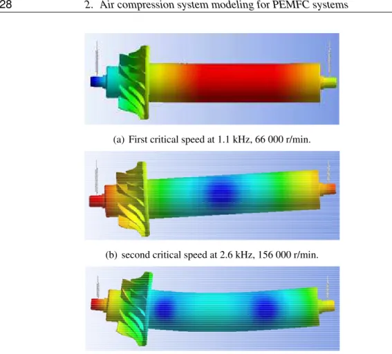
Besides the design of the individual components, rotor dynamics of the common rotor of the electrical machine and the centrifugal machine is required. The critical speeds of the rotor are depicted in Figure 18. In the field of rotordynamics, the critical speed is the theoretical angular velocity that excites the natural frequency of the rotor. As the speed of rotation approaches the object’s natural frequency, the object begins to res-onate, which dramatically increases system vibration. The critical speed calculations have been made during the electrical machine optimization process with an analytical approach in order to define geometric constraints for the machine. The final rotor dy-namic design has been verified with 3D finite-element (FE) simulations. The rotor is designed such that the nominal speed of 250,000 rpm is below the first bending mode (third critical speed), but above the two bearing modes (two first critical speeds).
(a) First critical speed at 1.1 kHz, 66 000 r/min.
(b) second critical speed at 2.6 kHz, 156 000 r/min.
(c) third critical speed at 8 kHz, 480 000 r/min.
Fig. 18. Critical speeds of the centrifugal compressor rotor. (Blue) No displacement. (Red) Maximal displacement.
The realized compressor prototype has a weight of 0.6 kg which is fifty times lower than a comparable scroll compressor. The compressor has been evaluated on a test bench. The measurement of the compressor and power map data is in very good agree-ment with the calculations as can be seen in Figure 19. The measured compressor efficiency in the rated operating point is 74.8 % which is also very close to the de-signed efficiency. The motor and converter efficiency in the rated operating point is 92 % and 90.6 % respectively. This results in a total system efficiency of 62.3 %. The centrifugal compression system is characterized by the compressor map, the ac-tuator dynamics, and the manifold model. The compressor map gives the relation of speed, pressure, and mass flow. A speed motor controller and valve position controller, which are treated as embedded devices, have been developed and described. The man-ifold model describes the dynamics of the pressure and mass flow.
2.1. An ultra-high speed compressor 29
(a) Calculated and measured compressor map.
(b) Calculated and measured power map.
0 5 10 15 20 25 0 20 40 60 80 100 Mass flow (g/s) Motor−Isentrop Efficiency (%) 100 krpm 120 krpm 140 krpm 160 krpm 180 krpm 200 krpm 210 krpm 220 krpm 230 krpm 240 krpm 250 krpm 260 krpm
Fig. 20. Compressor efficiency map.
2.2
Compressor modeling
2.2.1 Compressor map modeling overviewThe compressor map which gives the relationship of the speed ω, mass flow q, and pressure ratio p is one information we can get from the manufacturer. However, to find the mathematical relationship of the three variables is not an easy task. An accu-rate model of the compressor map can help us to analyze its characteristic and further adapt it to the air management system. Several methods have been described about the compressor map modeling in the literature.
J.Gravdahl et al. [67] described the compressor characteristic with a third order poly-nomial approximation which is obtained by the curve fitting using the measured data. The first step is to find the relation between the mass flow and pressure, fixing the speed constant. The second step is to fit the speed behavior through a third order polynomial equation with the coefficients to be determined.
In [68], auxiliary coordinates (linesβ) which have no physical meaning, are introduced to describe the characteristic curves . In [69], with measured compressor
characteris-2.2. Compressor modeling 31
tics, the coefficients of the theoretical implicit relations, Jensen & Kristensen method, are determined by the curve fitting through least square methods. Many parameters, such as the compressor diameter, air density, air gas constant, etc., are needed in the theoretical equation.
R.Tirnovan et al. proposed and presented a moving least squares (MLS) algorithm for obtaining a surrogate model of the centrifugal compressor [70]. The use of MLS is justified by the fact that it is a powerful method for approximating a function when few data available.
Neural network based method was employed in [71–73] to develop the compressor map. A.Lazzaretto and A.Toffolo use the output power to predict the compressor performance (pressure, mass flow, efficiency, etc) through constructing a neural net-work [72].
A generalized compressor map was developed by Saravanamuttoo and MacIssac [74] using four different methods, including neural networks, and tested on three different compressors. And the fitting accuracies, model complexities, genericities and extrap-olation capabilities are compared.
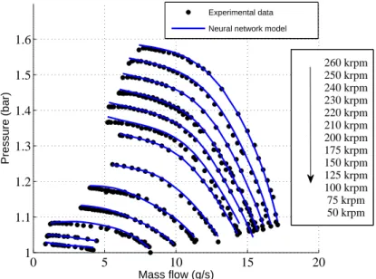
Compare with other fitting methods, the neural network technology is superior in terms of the fitting accuracy. Moreover little parameter information about the compressor is needed. Nevertheless, because of the complexity of the neural network model its com-putation is time consuming. However, for our applications, the compressor model is only used for the system analysis off-line, such as the coupling characteristics between the mass flow and pressure. Therefore, the complexity of the model dose not influence the control in real time. In this thesis, the neural network method is used for the map fitting.
2.2.2 Compressor map measurement
The measured compressor map normally has a great relation with the circumstances, such as the ambient temperature, the ambient pressure, and the accuracy of the sensors. Therefore, the compressor map is remeasured on our testbench instead of using the manufacture provided map.
0 100 200 300 400 500 600 700 800 0 5 10 15 20 Po w e r (W) Mass flow (g/s) 150 krpm 175 krpm 200 krpm 220 krpm 240 krpm
Fig. 21. Measured compressor power.
1.000 1.100 1.200 1.300 1.400 1.500 1.600 1.700 0 5 10 15 20 P res su re (bar) Mass flow (g/s) 50000 75000 100000 125000 150000 175000 200000 210000 220000 230000 240000 250000 260000 surge line
2.2. Compressor modeling 33
By throttling down the compressor towards the surge line, the mass flow and pressure are measured while keeping the speed constant. The surge phenomenon is character-ized by the large noise of the compressor with the oscillations of the mass flow and pressure. While measuring, at each point sufficient time is needed to wait the system operate at state. The power at different speed is shown in Figure 21. The steady-state compressor map and the approximation of the surge line are measured as shown in Figure 22. As the measuring going close to the surge line, the pressure becomes nonsensitive to the mass flow variation. The system is not stable when operating to the left of the surge line.
2.2.3 Neural network modeling
A neural network is composed of groups of connected neurons, simple processing units, which has the ability of learning and storing knowledge obtained during the training. Normally, it consists of three components: input layer, hidden layers and output layer. In theory, a neural network can approximate an arbitrary mathematical function as long as the hidden layer has adequate number of neurons. In this thesis, a static BP based neural network with two hidden-layers is developed based on the measurement. The BP learning process works in iterative steps: The error between the network output and the known-good output is backwards each step to verify the weights in each layer reducing the error.
The structure of the trained network model is shown in Figure 23. This model is de-cided by training and evaluating different structures, from a simple one to the more complex structures. Maybe the selected one is not the most optimal approach hav-ing the minimum neurons. However, it will not influence the system analysis by the Simulink. The developed model involves two hidden layers and uses the speed and pressure to determine the mass flow. In the first hidden layer, tan-sigmoid is selected as the transfer-function. Whereas, purelin is the adopted transfer-function in the sec-ond hidden layer as well as the output layer.
15 neurons 8 neurons 2 hidden layers
mass flow speed
pressure
Fig. 23. Neural network model of the centrifugal compressor.
The equations used in this model are detailed as follows: The output of the neural network model:
q= purelin(w1β1+ w2β2· · · w8β8+ d) (2.1)
The second hidden layer outputs:
βj= purelin(l1, jα1+ l2, jα2· · · l15, jα15+ ej), j = 1, 2 · · · , 8 (2.2) The first hidden layer outputs:
αi= tansig(aip+ biω + ci), i = 1, 2 · · · , 15 (2.3) where q, p, ω are the mass flow, pressure and speed respectively. wj, li, j, ai, biare the weight coefficients. d, ej, ciare the biases. purelin(·) and tansig(·) are linear transfer function and hyperbolic tangent sigmoid transfer function respectively. The mathemat-ical expressions of these two functions are purelin(x) = x and tansig(x) = 1+e2−2x− 1
![Fig. 4. Schematic of fuel cell stack with internal humidifier [7].](https://thumb-eu.123doks.com/thumbv2/123doknet/14528323.723195/24.892.301.661.563.862/fig-schematic-fuel-cell-stack-internal-humidifier.webp)