Publisher’s version / Version de l'éditeur:
Concrete International, 19, August 8, pp. 68-72, 1997-08-01
READ THESE TERMS AND CONDITIONS CAREFULLY BEFORE USING THIS WEBSITE. https://nrc-publications.canada.ca/eng/copyright
Vous avez des questions? Nous pouvons vous aider. Pour communiquer directement avec un auteur, consultez la
première page de la revue dans laquelle son article a été publié afin de trouver ses coordonnées. Si vous n’arrivez pas à les repérer, communiquez avec nous à [email protected].
Questions? Contact the NRC Publications Archive team at
[email protected]. If you wish to email the authors directly, please see the first page of the publication for their contact information.
NRC Publications Archive
Archives des publications du CNRC
This publication could be one of several versions: author’s original, accepted manuscript or the publisher’s version. / La version de cette publication peut être l’une des suivantes : la version prépublication de l’auteur, la version acceptée du manuscrit ou la version de l’éditeur.
Access and use of this website and the material on it are subject to the Terms and Conditions set forth at
Electrochemical incompatibility of patches in reinforced concrete
Gu, P.; Beaudoin, J. J.; Tumidajski, P. J.; Mailvaganam, N. P.
https://publications-cnrc.canada.ca/fra/droits
L’accès à ce site Web et l’utilisation de son contenu sont assujettis aux conditions présentées dans le site LISEZ CES CONDITIONS ATTENTIVEMENT AVANT D’UTILISER CE SITE WEB.
NRC Publications Record / Notice d'Archives des publications de CNRC:
https://nrc-publications.canada.ca/eng/view/object/?id=efb2b19b-8792-41c1-a755-a2069ca67adf https://publications-cnrc.canada.ca/fra/voir/objet/?id=efb2b19b-8792-41c1-a755-a2069ca67adf
http://www.nrc-cnrc.gc.ca/irc
Ele c t roc he m ic a l inc om pa t ibilit y of pa t c he s in re inforc e d c onc re t e
N R C C - 3 6 0 5 4
G u , P . ; B e a u d o i n , J . J . ; T u m i d a j s k i , P . J . ;
M a i l v a g a n a m , N . P .
A u g u s t 1 9 9 7
A version of this document is published in / Une version de ce document se trouve dans:
Concrete International, 19, (8), August, pp. 68-72, August 01, 1997
The material in this document is covered by the provisions of the Copyright Act, by Canadian laws, policies, regulations and international agreements. Such provisions serve to identify the information source and, in specific instances, to prohibit reproduction of materials without written permission. For more information visit http://laws.justice.gc.ca/en/showtdm/cs/C-42
Les renseignements dans ce document sont protégés par la Loi sur le droit d'auteur, par les lois, les politiques et les règlements du Canada et des accords internationaux. Ces dispositions permettent d'identifier la source de l'information et, dans certains cas, d'interdire la copie de documents sans permission écrite. Pour obtenir de plus amples renseignements : http://lois.justice.gc.ca/fr/showtdm/cs/C-42
Electrochemical
Incompatibility of Patches
in Reinforced Concrete
by
Ping Gu, J.J. Beaudoin, P.J. Tumidajski, and N.P. Mailvaganam
,
(
.
, .
he annual expenditure for re-pair and rehabilitation of con-crete structures exceeds 50 percent of the total co'nstruc-tion costs. IIt is expected that this trend will continue at least to the year 2000. The large market for repair materials and specialized techniques has driven the need for substantial research and development targeted at improved per-formance and extended service life. 2-s Issues include the development of new durable materials, repair material com-patibility, and suitability of materials for specific environments.
More recently, attention has focused on material compatibility and durabili-ty of the repair. The term compatibilidurabili-ty has been defined by Emmons et aI.' as a balance of physical, chemical, and electrochentical properties and dimen-sions between a repair material and the existing substrate. This balance will in-sure the repair can withstand all the stresses induced by volume changes and chemical and electrochemical ef-fects without distress and deterioration. A summary of factors that affect the
compatibility of repair materials was given by Emmons et al.,10 Emberson and Mays,ll-12 Morgan,13 and others. 14 They include chemical, electrochemi-cal compatibility, and sintilarity in per-meability and dimensional stability.
An understanding of the electro-chemical principles involved in incom-patibility is essential to insure a durable repair. Although the importance of the electrochemical compatibility between repair materials and the existing con-crete substrate has been dis-cussed,'·IUI3-15 the underlying electrochemical principles have not been well explained. In this paper, the causes of electrochentical incompati-bility in the reinforced concrete patch repairs are discussed in tenus of basic electrochemical principles. Guidelines are suggested to ntitigate the incompat-ibility.
Electrochemical incompatibility
Electrochemical incompatibility is due to the electrochemical potential imbal-ance (EPI) caused by two materials in
contact, usually metals. The EPI usual-ly results in an accelerated corrosion of the electrochemically less noble mate-rial. This concept, however, is slightly different when it is applied to rein-forced concrete patch repair.It refers to the EPI occurting in different locations of the reinforcing steel bar because of the dissimilar environments causedby
a concrete patch repair.
The EPI is caused by a variety of fac-tors including physical properties (i.e_, density, porosity and permeability) and chemical compositions of the repair material and the existing unrepaired concrete substrate. The basic electro-chentical principles and their applica-tion to the reinforced concrete patch repair are discussed in the following sections.
Basic principles
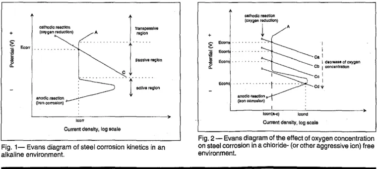
The Evans diagram is commonly used to understand the kinetics of steel cor-rosion_16Fig. I illustrates the steel
cor-rosion kinetics in an alkaline
environment. Curve A refers to an oxi-dation (anodic) reaction of reinforcing
Current density, log scale
A
Current density, log scale
I I Ca I I dllcrliIa&e of oxygen Cb I concentration Co I I Cd'+"
J
cathodic reaction (oxygen redUction)1
A + セ ]jj Sco - - . 55 Etorr "5 "-Ecell'1-anodlo reactlon (iron ool1'o$lon)
,
lcorr(a-c) Icarroi
transpasslveI
region...J,.."""""
...
ᄋャᄋセセZ
:.,,,"
,,,"
cathodic Ulaotion (oxygen reduction) anodic reaction (Iron corrosion) + セ Ecorrセ
セ Cl.Fig. 1-Evans diagram of steel corrosion kinetics in an alkaline environment.
Fig. 2 - Evans diagram of the effect of oxygen concentration on steel corrosion in a chloride- (or other aggressive ion) free
environment.
,steeL There are three anodic regions:
active, passive and transpassive in an
alkaline environment without aggres-sive ions. Curve C is the cathodic
reac-tion representing the oxygenreduction reaction, The intercept of these two curvesAand C, where the anodic tion rate is equal to the cathodic reac-tion rate, is the corrosion potential,
Ecorr, and corrosion current density,
Icorr, Normally, the reinforcing steel is stable in a concrete because the cathod-ic curve intercepts the anodic curve in
the passive region. In this case, the re-inforcing steel is protected by a surface oxide film and the corrosion rate, leorr, is almost negligible.
Effect of oxygen concentration on steel corrosion
The Evans diagram illustrating the ef-fect of oxygen concentration on steel corrosion in a chloride- (or other ag-gressive ion) free environment is given in Fig, 2, Curve A represents the anodic
reaction (iron corrosion) and curves
Ca-Cd are cathodic reactions
represent-ing various initial oxygen
concentra-tions available at the steel snrface. The cathodic curve Ca moves toward a more negative potential (such as curves Cb or Cc) as the initial oxygen concentration decreases and results in a decrease (more negative) in the corro-sion potential (i.e., the point where the cathodic and anodic reaction curves in-tercept). However leorr remains small when the intercept falls in the passive region, Itis possible that a large leorr
could occur when oxygen
concentra-tion is extremely low (curve Cd), where the interception of the two curves falls into the steel active region (Icorrd, Fig.
2),
Effect of chloride ion
concentration on steel corrosion
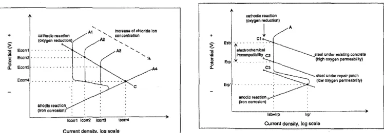
Fig, 3 is the Evans diagram for the
ef-fect of chloride ion contamination on
steel corrosion, Chloride ions break down the protective oxide film on the steeL Curve C is the cathodic reaction
and the A curves are anodic reaction
curves for the steel in the presence of various chloride ion concentrations. As
chloride ion concentration increases there is a reduction in the passive re-gion and the anodic reaction curves
shift from Al to A3, In the extreme case (A4), the passive region
disap-pears. The corrosion potential
decreas-es (Ecorr I<Ecorr2<Ecorr3<Ecorr4)
and the corrosion rate, Icorr, increases
(leorr I>leorr2>Icorr3>Icorr4),
Electrochemical
incompatibility
resulting from
patch repair
A patch repair is often applied in re-pairing reinforced concrete damaged
due to corrosion to restore a protective environment to the reinforcing steel.
The repair procednre normally in-volves the following steps:16a saw cut
or chip of the vertical patch edge; re-moval of all unsound concrete; a clean-ing of the reinforcclean-ing steel to bare metal; application of a cementitious bonding grout or epoxy coat and proper placement, finishing, and curing of the patch materiaL
The concrete is usually cut back far enough to insure that all the carbonated or chloride contantinated and unsound concrete is removed. A cleaning of the
reinforcing steel surface and removal
of the corrosion products (rust) is nec-essary to restore the steel surface
passi-vation condition before a repair
material is applied. This procedure,
however, may cause dissimilar envi-ronments between the existing concrete
and the repair patch leadingtothe
oc-currence of the electrochemical
incom-patibility, Two hypothetical cases are analyzed to demonstrate this point
• Case I - Dense repair patch in a porous concrete substrate
An electrochemical potential imbal-ance at the reinforcing steel bar can
oc-cur when a dense concrete repair is
surrounded by a porous concrete sub-strate. The situation is shown in Fig. 4,
Curve A is the anodic reaction and curves C I and C2 are cathodic reaction curves for steel areas covered by the existing concrete substrate and the re, pair, respectively. Since the existing concrete substrate adjacent to the repair patch is porous and the oxygen perme, ability is relatively high, the corrosion potential of the steel in such an area, Esb, is higher than Erp, the corrosion potential of the steel area covered by the repair patch, The electrochemical potential difference, IEsb-Erpl, occurs due to the patch installation and its am-plitude represents the magnitude of the electrochemical incompatibility. In this case, the electrochemical potential
dif-ference occurs because of the uneven
oxygen availability - caused by the porosity or density differences between the existing concrete substrate and the repair patch,
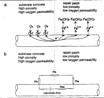
The electrochemical potential
imbal-ance results in an oxygen corrosion
macrocelL The reinforcing steel em-bedded underneath the denser repair develops a local "anodic area" (Fig, Sa)
where corrosion accelerates. Oxygen reduction occurs at local "cathodic
ar-eas" in the adjacent reinforced concrete substrate where the oxygen concentra-tion is high, + oa1hodlc reacUon セ (oxygen Tsdudlon)
"
Eoorrl . セ Ecorr2 ."
セ Ecoff3 . Ecorr4 . . . . .- - -セ-,
A1 " " "..
セ」セセZセセ[エ[セセioイゥ、・icョ, ,
,
AS " c + catllodlc reaolion (OK)'gan reduction))
Esb -" . tlllOlrOChilmiCal.I
セュ」ッュー。エゥ「ャャャエケ C2 Elp .'t'. . __ . . . . C, anodicイウ。」セッョ : (Iron corrosion) A iセGsteel under e_Wlng concrete (high Oxygen permeability)
steel under repair patch (tow oxygen permeability)
loorrl 100172 IcolT3 Current density. log scale
Fig, 3 - Evans diagram of the effect of chloride ion
contamination on steel corrosion.
August 1997
Current density, log scale
Fig, 4 - Schematic of an electrochemical potential
imbalance at the reinforcing steei bar when a dense concrete repair is surrounded by a porous concrete substrate,
chloride free
repair patch
chloride free repair pa1ch
where the cell voltage is Ve=
Erp-Esb.
The effect of the chloride macrocell is more problemat-ic than the oxygen macrocell because the chloride macro-cell is autocatalytic. The steel corrosion lowers the pH value and accumulates positive ions (Fe++) at the local "anodic ar-eas." The excess positive charges are balanced by the migration of more chloride ions. Both effects subsequent-ly increase corrosion rate.
The use of
"like-like" quality in patch repair
The use of a repair material that has a similar quality (including similar po-rosity, etc.) to the existing concrete is recommended when a dense repair
ma-terial causes electrochemical
incom-patibility. This can reduce the electrochemical potential difference due to different oxygen permeabilities
Minimizing electrochemical incompatibility
An understanding of the elec-trochemical principles behind the reinforced concrete patch repair is significant for estab-lishing guidelines that insure a durable repair. The following
suggested measures can
sig-nificantly reduce the electrochemical incompatibility. chloride contaminated substrateconcrete chloride contaminated substrate concrete F\S
Rob
'--Rs, ]RC
t
Ue_Erp_EsbI
d
repair patch low porositylow oxygen permeability
repaIr patch
low porosity
low oxygen permeability
b
Concrete International
a
Fig. 7 a and b - Effects 01 electrochemicai incompatibility due to a chloride macroceli: (a) corrosion mechanism, and (b) eiectrical equivaient circuil.
R' substrate concrete high porosity
high oxygen permeability:
substrate concrete high porosity
high oxygen permeability:
steel area embedded in the existing chloride contaminated concrete.
An electrochemical potential differ-ence, IErp-Esbl, exists in such a repair leading to a chloride concentration macrocell. The reinforcing steel area embedded in the existing chloride con-taminated concrete substrate develops a local "anodic area" (Fig. 7a) where
corrosion rate is much higher
(Isb»Il'p, Fig. 6). Oxygen is reduced at "cathodic areas" where the repair was made. The chloride macrocell can also be described using an electrical equivalent circuit shown in Fig. 7b
-,----R-Jcb-!---'-,
セr]MMGセャGMM⦅M MAMM|セlr⦅o MMセ
t
U.=E,b-E",J
steel under existing」ッョセイエ・ (chloride Ion conlamlnalQd)
c
'ob
a
b
Fig. 5 a and b - Effects of electrochemical incompatibility due to an oxygen macroceli: (a) corrosion mechanism, and (b) eiectricai equivalent circuil.
A
anoolc rsaellon (Iron corrosion)
iセ
Current density, logsaale
I stGei under repair paleh
I (clQrldalon free)
I
cathodic reaction A
(oxygen reduction)
E"
I·
[''''o'om,,,,
esJ _
イュ」セセーN。セ「セュy
..+
The oxygen macrocell can be represented by an electrical equivalent circuit (Fig. 5b) where the elements Ra, Rc, Rst, and Rs are the anodic po-larization, cathodic polariza-tion, steel and concrete resistances, respectively. The driving force is Ve - the po-tential difference of Esb and Erp. Significant acceleration of corrosion underneath the repair patch does not always happen. However, this is true only when the cathodic curve intercepts the anodic curve in the passive region (curves CI and C2, Fig. 4 where the Isb=
Irp). The corrosion of steel can be greatly accelerated for conditions of extremely low
initial oxygen concentration.
In this case, the value of cor-rosion rate Irp' is much higher than lsb. Therefore, it is pru-dent to verify the substrate
condition when very dense repair mate-rials are targeted for use.
o Case1\ - Repair patch in
chloride contaminated concrete
Although chloride contaminated,
un-sound concrete is normally removed
prior to a repair, electrochentlcal poten-tial imbalance can also occur because of the difference in chloride ion con-centration between the chloride free patch and the substrate which usually contains some chloride. Fig. 6 illus-trates this condition. Curve Al is the anodic reaction for the reinforcing steel area underneath the chloride free repair patch whereas curve A2 is the anodic reaction for the adjacent reinforcing
Fig. 6 - Schematic of an electrochemicai potential imbalance at the reinforcing steel bar whan a chloride free concrete repair is surrounded by a chloride contaminated concrete substrate.
Fig. 8 - A schematic illustration of measures to minimize electrochemicai incompatibility in repair: (a) like-like quality repair, (b) chloride removal, (c) use of anodic corrosion inhibitor, and (d) use of cathodic corrosion inhibitor.
E(..)
b E( ..) a
existing eonc''''e
,
..
chlorldsll'l1l1!ep/l1'"
(high O>lYgenpormGability!
·ElP' paleh .. . ... • ·Esb'
apply rapalrpalcn thet apply chlonde ltmovalto has BlmliB.r po,oslty to 1M thebIャjャセョァ lub.lnlle tubtlratelo reduce Ine prlorto the repair tor&dUCB
pOlenijBI\ゥセNイエョcr the pcl1entlal dirle,ence
denn rspalrpatch-
,.
chlOrtde cont8mlnat,
..
(lowッセァNョ plrmubll" BXistlng ClCIne,ele
E{-) E(·)
E(+) d E(+)
C
eri.Ung cone'ete
".
chlorkl&treerepa1 '.
(high OllY\lenpBrmBabilill') .- - -_.
·ElP' patch
applyMOIlIOcorrooton ealhodlOInhilitel admil<lUro Inhibiting admixture Inthe mo(mk:/ltlon of therepair palch
repair pate!l to rBduoe
•.セセセセZZi・ョセ。ャセ・イッセ・ Ihe potentia!、セANイ・ョ」・
denn ,epa.!r pato
'.
ッョャッセHi・ contamlM,
..
(lOWッセァ・ョ permubil eJdllllng ccllO,ete
E(·) E(-l
between the repair and the existing concrete substrate (Fig. 8a). However,it should also be noted that a low quality repair patch designed to match the substrate con-crete is vulnerable to car-bonation attack and chloride ion penetration.
Chloride removal
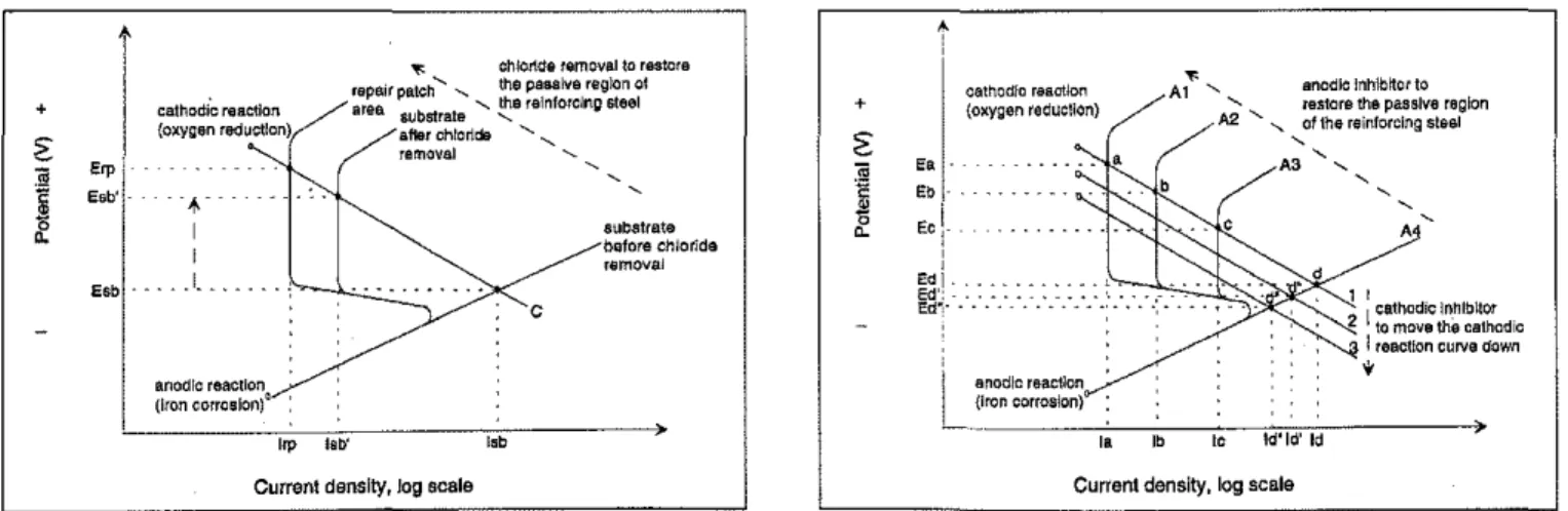
Chloride ions can be effec-tively removed from the contaminated concrete with an electrochemical tech-nique. Chloride removal pri-or to the repair could be very useful since it not only re-moves the chloride ions from the existing concrete but also restores the rein-forcing steel back to a pas-sive condition through realkalization of the steel surface (Fig.9).
The corrosion potential of
the concrete substrate, Esb, shifts to Esb' after the chloride removal. It re-duces the electrochemical potential dif-ference between the reinforcing steel area underneath the existing concrete and the repair patch from IErp-Esbl to IErp-Esb'l as described in Fig. 8b and 9. However, this measure increases the repair costs and raises other concerns such as hydrogen evolution.
Use of corrosion inhibitor
The corrosion potential of steel can be modified through the use of corrosion inhibitors. The shift of the corrosion potential can be positive or negative depending on whether an anodic or ca-thodic inhibitor is applied. An anodic
corrosion inhibitor is a passivator or a strong oxidizing agent. Itrestores and strengthens the protective oxide film formed around the steel as indicated in Fig. 10.
Curve A4 represents a complete break down of the oxide film of a steel surface in the presence of appreciable levels of chloride ions. The anodic in-hibitor restores the steel surface oxide film as indicated by curves A1-A3 (de-pending on the concentration levels of the anodic inhibitor and the inhibi-tor/chloride ratio). This is accom-plished through a redox reaction in which the inhibitor is reduced and the steel becomes oxidized to form ferrous hydroxides and ferric oxides.
This implies that the rest potential of the steel is shift-ed positively to the passive region (intercepts a, b, c, Fig. 10) where a film of tightly adhering corrosion products prevents any fur-ther release of ferrous ions. The corresponding corro-sion rate is therefore signifi-cantly reduced (la, lb,Ie
«
Id, Fig. 10).la contrast to an anodic in-hibitor, a cathodic inhibitor reduces corrosion by retard-ing individual stages of the cathodic processes such as ionization of oxygen, diffu-sion of oxygen to the cath-ode and discharge of protons at the electro-active site on the steel, which naturally lead to a reduction of corro-sion current. Fig. 10 illus-trates the effect of the cathodic corrosion inhibitor which shifts the cathodic reaction (curve 1)toward the negative potential (curves 2 or 3). Such a parallel shift re-sults in a reduction of the corrosion rate (Id" <Id'<Id). A parallel shift is nor-mally determined by the initial reducer which is oxygen in this case.
A slope change in the cathodic curve may also occur if the cathodic inhibitor alters the cathodic reaction kinetics. Mixed corrosion inhibitors influence both the cathodic and anodic reactions. The rest potential may shift in both di-rections depending on the proton donor and electron acceptor functional groups.
The electrochemical incompatibility in the reinforced concrete patch repair
L
'
,_anOdiC reaction ___ .. (Iron corrosion) Ie ld'leI' ld d•
,
,
2 1セZセセセセ ゥjZZiセセiゥZo、ゥcI leecllon curve down
•
セ , anodiciョィャ「セッイ to
A1 , restore the passive region
A2 "
,
of the reinforcing steel,
.3 ,,
cathodicreactlOl'1 (o:tygen recluctlon) la Ib . . . a,
+z:
)
"
Eb 0 Ec !- "-, I セセLA:
e、セᄋ SUbstrate bllfors chloride removel c ',b"" chlonde removal to restore repair patCh' , the pessive region 01 erea substrateLセ・ relnfolclng s1eel
after chlorldll ' , removal 'II ,"tho";
セNBBB
, (o:tygen reduction) Irp lab' Erpj -",b'1 "..
I I Esb . • . . . 1•• +Currant density, Jog scale Current density, log scala
Fig.9 - Evans diagram of the effect of chloride removal on minimizing electrochemical Incompatibility in reinforced
concrete repair.
Fig. 10-Evans diagram of the effect of corrosion inhibitors on minimizing electrochemical incompatibility in reinforced concrete,
can be significantly reduced by incor-porating a corrosion inhibitor in the re-pair material. Depending on the physical and chemical properties of the existing concrete substrate and the patch material, anodic or cathodic cor-rosion inhibitors can be applied.
For instance, if the oxygen perme-ability causes the electrochentlcal po-tential imbalance, application of an anodic inhibitor is preferred because the reinforcing steel surface area under-neath the repair patch acts as an anodic area which has a more negative poten-tial than the adjacent steel area acting as cathodic area. Use of anodic corro-sion inhibitors will shift the electro-chentlcal potential of this anodic area toward a more positive value and will significantly reduce the electrochentl-cal potential difference between steel areas covered by the existing concrete and the repair patch. This results in a ntlnintlzation of the oxygen macrocell potential (Fig. 8c) and the corrosion rate (Fig. 10).
As another example, if the electro-chentlcal potential imbalance is caused by the chloride macrocell, the steel sur-face area underneath the chloride free repair patch is cathodic. In this case, use of a cathodic corrosion inhibitor is advisable.
The cathodic inhibitor lowers the electrochentlcal potential of the steel area covered by the repair to match the potential of the adjacent steel area em-bedded in existing chloride contantl-nated concrete. Consequently, it reduces the electrochemical potential difference of the reinforcing steel em-bedded in both matrices as indicated in Fig. 8d and retards the corrosion reac-tion. Furthermore, in the interest of ex-tending the service life of the repair, a
breathable silane or siloxane sealer
which restricts chloride ion ingress should be applied to the patch area.
Conclusions
The durability of a repair depends on many factors and the electrochentlcal incompatibility may be a combined
ef-fect of many influences. However, an
understanding of the electrochentlcal potential imbalance in patch repair can serve as a useful guide to achieve dura-ble repairs. The basic electrochentlcal corrosion principles can explain the electrochentlcal incompatibility in the reinforced concrete repair.
The phenomenon always occurs due to the physical, chentlcal, and
electro-72
chemical dissimilarities between the existing concrete substrate and the re-pair patch that covers the reinforcing steel. Guidelines can be developed for patch repair remedies to reduce the electrochemical incompatibility and to enhance the durability of the repair.
Although real construction repairs are not as ideal as discussed here, it is hoped that the principles implicit in the illustrated examples will stimulate fur-ther thought along these lines.
References
1. Mailvaganam, N,P.. and Alexander, T.. "Se-lection of Repair Materialswith Expert Advice,"
Concrete Repair Bulletin, 12-15 (1996).
2. Gulikers.J.J.w.,and Van Miee, lO.M., ''The
Effect of Patch Repairs on the Corrosion of Steel
Reinforcement in Concrete," Second
ean-met/ACI International Conference on Durability
of Concrete, Supplementary Papers, Montreal, Canada, 1991, pp. 445-460.
3. Schiessl, P., and Raupach, M" "Macrocell Steel Corrosion in Concrete Caused by Chloride in Concrete," Second CanmetlACI International Conference on Durability of Concrete, SuppleM mentary Papers, Montreal, Canada, 1991, pp.
565-5S3.
4.Marosszeky,M.,and Wang, D., "The Study
of the Effect of Various Factors on Subsequent Bar Corrosion in Concrete," Second CanmetlACI International Conference on Durability of ConM crete, Supplementary Papers, Montreal, Canada,
1991, pp. 585-606.
5.McCurrich, L.H.; Cheriton, L.W.; and Little,
D.R., "Repair System for Preventing Further Corrosion in Damaged Reinforced Concrete," 1st International Conference on Deterioration and Repair of Reinforced Concrete in the Arabian Gulf, Bahrain, October 26-29, 1985, pp.
151-168.
6. Plum, D., "Materials - What to Specify,"
Construction Maintenance & Repair,
July/Au-gust 1991, pp. 3-7.
7. Heiman,l.L.,and Koerstz, P., "Perfonnance of Polymer-Modified Cementitious Repair Mor-tars in Chloride Contaminated Concrete,"Trans. Inst. Eng. Austral. Civ. Eng.,V. 33,No.3, 1991,
pp.169-175.
8. Dehwah, H.AF.; Basunbul, lA;
Maslehud-din,M.;AIMSulaimani, GJ.; and Baluch, M.H.,
"Durability Perfonnance of Repaired Reinforced Concrete Beams,"ACI Materials Journal, V.93,
No.2, March-ApriI1994, pp. 167-172.
9. Emmons, P.H.; Vaysburd, AM.; and Mc-Donald, J.E.,"A Rational Approach to Durable Concrete Repairs,"Concrete International,V.IS,
No.9,September 1993, pp.40-45.
10. Emmons, P.H.; Vaysburd, AM.; and Mc-Donald, J.E.,"Concrete Repair in the FutureTurn
of the Century - Any Problems?"Concrete
In-ternational,V. 16, No.3,March1994,pp.42-49. 11.Emberson,N.K.,and Mays,a.c., "Signifi-cance of Property Mismatch in the Patch Repair
of Structural ConcretePart 1: Properties of
Re-pair Systems,"Magazine of Concrete Research,
V.42, No. 152, 1990, pp. 147-160.
12.Emberson,N.K.,and Mays,
a.c.,
"SignifiM cance of Property Mismatch in the Patch Repairof Structural Concrete·Part- 2: Axially Loaded
Reinforced Concrete Members," Magazine of
Concrete Research, V. 42, No. 152, 1990,pp.
161-170.
13. Morgan,n.R.,"Compatibility of Concrete
Repair Materials and Systems," Construction
and Building Materials,V. 10, No.1, 1996, pp.
57-67.
14.Cusson, D., and Mailvaganam,N.P.,"DuraM bility of Repair Materials,"Concrete IntemationM ai,V. 18. No.3, March 1996, pp. 34-3S.
15.Mailvaganam,N.P.,Repair and Protection
ofConcrete Structures, CRC Press Inc., Boca
Ra-ton, Florida, 1992.
16. Fontana, M.a., Corrosion Engineering,
third edition, McGraw-Hill Book Company,
1986, pp. 153-218.
Selected for reader interest by the・、ゥエッイウセ