Publisher’s version / Version de l'éditeur:
Vous avez des questions? Nous pouvons vous aider. Pour communiquer directement avec un auteur, consultez la première page de la revue dans laquelle son article a été publié afin de trouver ses coordonnées. Si vous n’arrivez pas à les repérer, communiquez avec nous à [email protected].
Questions? Contact the NRC Publications Archive team at
[email protected]. If you wish to email the authors directly, please see the first page of the publication for their contact information.
https://publications-cnrc.canada.ca/fra/droits
L’accès à ce site Web et l’utilisation de son contenu sont assujettis aux conditions présentées dans le site LISEZ CES CONDITIONS ATTENTIVEMENT AVANT D’UTILISER CE SITE WEB.
10th IBPSA Building Simulation Conference: [Proceedings], pp. 1-8, 2007-09-03
READ THESE TERMS AND CONDITIONS CAREFULLY BEFORE USING THIS WEBSITE.
https://nrc-publications.canada.ca/eng/copyright
NRC Publications Archive Record / Notice des Archives des publications du CNRC :
https://nrc-publications.canada.ca/eng/view/object/?id=959487a5-4c7a-42da-960f-3106bffadd5f https://publications-cnrc.canada.ca/fra/voir/objet/?id=959487a5-4c7a-42da-960f-3106bffadd5f
NRC Publications Archive
Archives des publications du CNRC
This publication could be one of several versions: author’s original, accepted manuscript or the publisher’s version. / La version de cette publication peut être l’une des suivantes : la version prépublication de l’auteur, la version acceptée du manuscrit ou la version de l’éditeur.
Access and use of this website and the material on it are subject to the Terms and Conditions set forth at
The Daylight coefficient method and complex fenestration
Laouadi, A.; Reinhart, C. F.; Bourgeois, D.
http://irc.nrc-cnrc.gc.ca
T h e d a y l i g h t c o e f f i c i e n t m e t h o d a n d c o m p l e x
f e n e s t r a t i o n
N R C C - 4 9 4 5 5
L a o u a d i , A . ; R e i n h a r t , C . F . ; B o u r g e o i s , D .
A version of this document is published in / Une version de ce document se trouve dans: 10th IBPSA Building Simulation Conference, Beijin, China, Sept. 3-6, 2007, pp. 1-8
The material in this document is covered by the provisions of the Copyright Act, by Canadian laws, policies, regulations and international agreements. Such provisions serve to identify the information source and, in specific instances, to prohibit reproduction of materials without
written permission. For more information visit http://laws.justice.gc.ca/en/showtdm/cs/C-42
Les renseignements dans ce document sont protégés par la Loi sur le droit d'auteur, par les lois, les politiques et les règlements du Canada et des accords internationaux. Ces dispositions permettent d'identifier la source de l'information et, dans certains cas, d'interdire la copie de
THE DAYLIGHT COEFFICIENT METHOD AND COMPLEX FENESTRATION
A. Laouadi
1, C. F. Reinhart
1, and D. Bourgeois
21
Institute for Research in Construction - National Research Council of Canada, 1200 Montreal
Road, Ottawa K1A 0R6, Canada
2
École d'architecture, Université Laval, Québec G1K 7P4, Canada
ABSTRACT
The daylight coefficient method has been introduced in computer simulation as an efficient approach to compute indoor daylight illuminances through building static fenestration systems. A set of coefficients are calculated only once prior to simulation start for a given number of elemental patches making up to sky vault and ground. However, for dynamic complex fenestration systems whose optical behavior (transmission, reflection and scattering) may change during simulation (such as windows with shadings), the efficiency of the daylight coefficient method may be compromised as the whole set of coefficients must be re-calculated during simulation. This paper presents the development of a new methodology to combine the daylight coefficient method with dynamic complex fenesration systems. The daylight coefficient is split into two components: one component corresponds to the unscattered transmitted light and the second to the scattered transmitted light. Both components are calculated based on the daylight coefficients of a reference fenestration, and the optical transmission characteristic and scattering effect of the actual fenestration. The resulting daylight coefficients for a given complex fenestration system may be calculated only once prior to simulation. This methodoly is implemented in Daylight 1-2-3, a new integrated energy and daylighting analysis tool for offices and classrooms. Initial validation studies, in which the results from the present method are compared with Radiance’s calculations, are carried out for a typical office space equiped with a clear window and interior Venetian blinds. The comparison shows that the new method is in good agreement with Radiance calculations, resulting in substantial simulation time savings.
KEYWORDS
daylighting; daylight coefficient; complex fenestration; blinds; daylight 1-2-3; SkyVision
INTRODUCTION
The daylight coefficient method is a rigorous and efficient approach to perform annual daylighting calculations through building static fenestration. The method, which was originally developed by Tregenza and Waters (1983), has been implemented
in many computer programs (Bourgeois et al., 2007; Mardaljevic, 2000; Janak, 1997; Tsangrassoulis et al., 1996). It consists of dividing the sky vault and ground into a number of elemental patches, and the corresponding daylight coefficients are calculated only once prior to the simulation start. Indoor illuminances are obtained at any time by summing up the illuminance contribution of each element over all patches upon knowing the sky luminance distribution. However, for dynamic complex fenestration whose optical behavior (transmission, reflection and scattering) may change during simulation (such as windows with shadings), the daylight coefficient method may not be efficient as the whole set of coefficients must be re-calculated during simulation. The aim of this paper is to develop a new methodology that combines the daylight coefficient method with dynamic complex fenestration with a minimum loss in computation efficiency. The intent of this work is to implement the developed method in Daylight 1-2-3, a new computer tool for integrated daylighting and energy simulation of offices and classrooms (Reinhart et al., 2007).
OBJECTIVES
The specific objectives are:
• To develop a new method to compute daylight coefficients through dynamic complex fenestration for annual daylight illuminance calculations.
• To validate the daylighting predictions using the present method with regards to the explicit calculations using the Radiance program.
• Implement the new method in Daylight 1-2-3.
METHODOLOGY
In the following, we present the development of a rigorous method, which combines the concept of the daylight coefficient and complex fenestration whose optical behavior may change over time.
The concept of the daylight coefficient
The concept of the daylight coefficient stems from the fact that the illuminance at a given point (Ei)
originating from a given point light source (denoted by i) is proportional to the luminance (Li) of the
source and its solid angle (dϖi) (Tregenza and Waters, 1983): i i i i DC L d E = ⋅ ⋅ ϖ (1)
ϖApplication of equation (1) to daylighting of a room space stipulates that the daylight coefficient at a given point (DCi) depends on the relative position
of the light source with respect to the room orientation, the room geometry, the optical characteristics of the room indoor surfaces, and the optical behavior (transmission, reflection and light scattering) of the fenestration system through which light is admitted into the room space. The advantage of this approach is that the daylight coefficient set may be calculated only once prior to simulation if the room variables and the optical behavior of its fenestration system do not change over time. Alternatively, if the optical behavior of fenestration changes only in magnitude, the daylight coefficient set may be initially calculated for an optically similar reference fenestration with a scaling factor to account for this change. However, the efficiency of the daylight coefficient approach may be compromised for dynamic complex fenestration (optical behavior changes with time) as the daylight coefficients must be timely re-calculated. To remedy to this problem, the optical behavior of fenestration must be explicitly known or calculated when needed using suitable optical models.
Optical Models of Complex Fenestration
Although there is no formal definition of a complex fenestration, for the purpose of this study, we define a complex fenestration as any glazing assembly that incorporates one or more scattering (not fully clear) glazing panes. Typical examples include clear windows combined with opaque or translucent shadings or blinds, frosted glass windows, etc. We characterise the optical behavior of complex fenestration by the total transmittance, reflectance and the forward and backward scattering (or haze). Computation of such optical characteristics of a fenestration system needs a specialized computer tool. This paper uses the optical models of SkyVision (NRC, 2006). SkyVision handles the performance of complex windows, shadings and skylights. A public version is available online fee of charge. The current research version (not released yet) features significant upgrades, namely new optical algorithms of complex glazing such as scattering glazing, fritted glass, perforated shading screens, draperies and Venetian blinds. Included in the upgrades, are algorithms for thermal performance of complex windows, shadings and domed skylights. More details on the optical models may be found in Laouadi and Parekh, (2007a). The models are based on the optical characteristics (transmittance,
reflectance) and the forward and backward haze properties of each glazing layer making up the glazing assembly. These models allow for computing not only the optical characteristics of the glazing assembly, but also the forward and backward haze property of the glazing assembly. Other optical indices for view-out and window luminance may also be computed, particularly for fenestration product rating purposes (Laouadi and Parekh, 2007b). Of particular interest to this paper are the optical models of Venetian blinds. The models of the Venetian blinds are based on the ISO 15099 standard (ISO, 2003), and can handle flat or curved slats with diffuse and/or specular optical properties.
Daylight Coefficients for Complex Fenestration
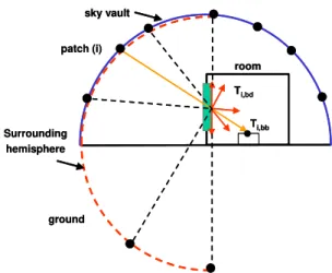
Following the optical models of SkyVision, the indoor daylight illuminances through complex fenestration are made up of two components: (1) scattered component which depends on the un-scattered component of the transmitted light; and (2) a scattered component which depends on the hazy or scattered transmitted light. SkyVision treats the scattered reflection or transmission as fully diffuse. For a beam light emanating from a given point light source, the corresponding DC is made up of two components: a beam-beam (unscattered) component (DCi,bs) and beam-diffuse (scattered) component
(DCi,bd) as follows (see Figure 1):
bd i bb i i DC DC DC = , + , (2) with: i i bb i bb i d L E DC ϖ ⋅ = , , (3) i i bd i bd i L d E DC ϖ ⋅ = , , (4)
To calculate the beam-beam component DCi,bb , a
reference clear fenestration is used and a variable, angle-dependent, scaling factor is employed to account for the actual fenestration system. In this regards, the reference fenestration should only have the same indoor-side reflectance as the actual fenestration. The beam-beam component of DCi,bb
is thus expressed as follows:
ref i bb i ref i bb i T T DC DC , , , , = ⋅ (5)
where Ti,bb is the beam-beam (un-scattered)
transmittance of a beam light emanating from the light source to the point under consideration, and Ti,ref is the transmittance of the reference fenestration
at the same incidence angle. It should be noted that the transmittance ratio in equation (5) denotes the variable scaling factor.
patch (i) ground room Ti,bd Ti,bb Surrounding hemisphere sky vault patch (i) ground room Ti,bd Ti,bb Surrounding hemisphere sky vault
Figure 1 Components of the daylight coefficient for a complex fenestration
To calculate the beam-diffuse DCi,bd, the
beam-diffuse transmitted light is treated as if it came from a hemispheric source with a uniform luminance (Lunif),
and transmitting through a clear fenestration having an equivalent transmittance equal to the beam-diffuse transmittance Ti,bd. The luminance of the
hypothetical hemispheric source is calculated so that the incident illuminance on the fenestration plane from the hemispheric source is equivalent to the one from the point source under consideration. This translates to the following:
π ϖ θ / cos i i i unif L d L = ⋅ ⋅ (6)
where θi is the incidence angle on the fenestration
plane of rays emanating from the point source (i). Dividing the hemispheric source into an N number of patches, the beam-diffuse illuminance (Ei,bd) is
expressed as follows:
∑
= = ⋅ ⋅ = j N j j unif unif j bd i DC L d E 1 , , ϖ (7)with DCj,unif are the daylight coefficients for the
hemispheric source surrounding the fenestration plane. By mapping the DCj,unif to the DCi,ref for the
entire sky vault, and substituting equation (6) in equation (7), one obtains:
∑
= = ⋅ ⋅ = N j j j ref j ref j bd i i bd i d T DC T DC 1 , , , , cos π ϖ θ (8)Assuming that dϖj =2π/N, equation (8) may reduce
to the following:
∑
= = ⋅ ⋅ ⋅ = N j j ref j dif ref bd i i bd i DC N T T DC 1 , , , , cosθ 2 (9)with Tref,dif is the hemispheric transmittance of the
reference fenestration.
Equation (9) holds for a horizontal fenestration where the entire sky vault can be mapped to the hemisphere surrounding the fenestration. For a vertical fenestration, the sky vault covers only half of the fenestration surrounding hemisphere, and the remaining part is attributed to the ground (Figure 1). If the ground is treated as one single light source with an equivalent daylight coefficient DCgr,ref,
equation (9) may be modified as follows:
⎪⎭ ⎪ ⎬ ⎫ ⎪⎩ ⎪ ⎨ ⎧ + =
∑
= = ref gr N j j ref j dif ref bd i i bd i T N DC DC T DC , 1 , , , , 2 cosθ (10)Equations (5) and (10) are applied to any single source daylight coefficient.
Using SkyVision, or any suitable fenestration software, the daylight coefficient sets given by equations (5) and (10) alongside with those for the reference fenestration may be evaluated for all possible light sources only once during the course of the simulation. For an annual daylight simulation through dynamic fenestration, a significant time saving may thus be achieved using this method, which would otherwise be prohibitive if a direct calculation method is used to compute the daylight coefficients at every time step.
Implementation in Daylight 1-2-3
The forgoing methodology was implemented in Daylight 3 (Reinhart et al., 2007). Daylight 1-2-3 integrates the Radiance and SkyVision programs to calculate the daylight coefficient set of a selected fenestration system. Radiance is used to calculate the reference daylight coefficient sets for the sky vault and ground using the new format (Bourgeois et al., 2007). The SkyVision tool is then used to modify the reference daylight coefficients based on the optical behavior of the selected fenestration system, according to equations (5) and (10). Daylight 1-2-3 offers a variety of fenestration products with clear and/or diffuse glazing. In-between pane or internal Venetian blinds may also be used with the selected fenestration to control glare and solar heat. Daylight 1-2-3 offers two options for the blind control: (1) OFF-when blinds are at the closed position, and (2) ON - when blinds are at the open or retracted position. Two sets of daylight coefficients are therefore calculated for the open and closed blind positions. This calculation procedure is performed only once prior to simulation.
Limitations
It should be noted that the foregoing methodology is limited to buildings without external obstructions and
to dynamic complex fenestration systems whose dynamic states are known a priori (such as two stage switchable glazing, or blinds with open and closed positions). For dynamic fenestration systems whose dynamic states are continuously changing with time (such as windows with Venetian blinds whose slat angles are modulated to block sunbeam light), the methodology may also be used during simulation but with reduced efficiency as the fenestration optics has to be calculated each time for all the elements of the daylight coefficients.
VALIDATION
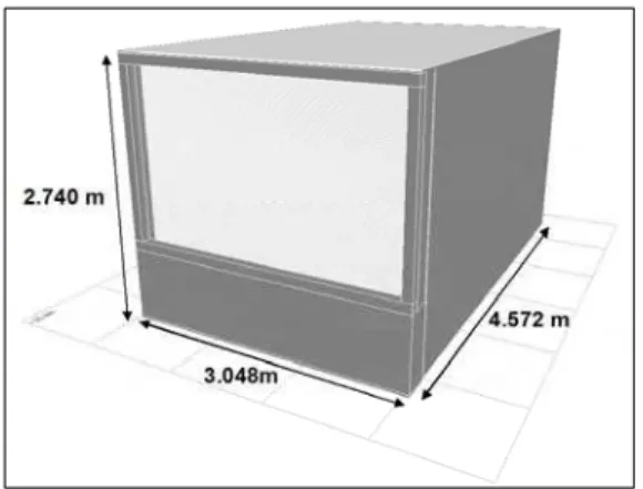
To validate the new method, a typical office space is used for the simulation. The office is equipped with a single glazed clear window and interior Venetian blinds. Figure 2 shows the office dimensions. The window glass transmittance and reflectance at a normal incidence angle are fixed at 80% and 7%, respectively. The dimensions of the Venetian blinds are: a slat width of 25mm, a curvature height of 2mm and a distance between the slats of 20mm. At the closed and open positions, the slat angle is fixed at 45o down and 0o, respectively. The slats are
opaque and diffuse with a reflectance of 70%.
Figure 2: Visualization of the office with the Venetian blinds closed.
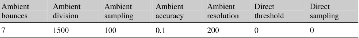
The Radiance program (Ward and Shakespeare, 1998) is used to explicitly model the window and blinds system, and compute the indoor illuminances. Radiance has extensively been validated for full scale geometries featuring light shelves (Mardaljevic 2000), Venetian blinds (Reinhart and Walkenhorst 2001), and translucent panels (Reinhart and Andersen 2006). For the purpose of this validation study, 14 series of illuminance sensors are uniformly deployed in the middle of the office running from the front to the back of the office. The front sensor #1 is positioned at 0.3 m off the window, and the back sensor #14 is positioned 0.3 m off the back wall. All sensors are positioned at a height of 0.88 m from the floor surface. Tables 1 and 2 show the Radiance office inputs and simulation parameters, respectively.
The resulting spatial resolution of the simulation is the maximum scene dimension x ambient accuracy / ambient resolution = 4900mm x 0.1 / 200 ~ 3mm. This spatial resolution is significantly smaller than the structure of the Venetian blinds. The simple model of Venetian blinds of the Lightswitch wizard (Reinhart et al., 2003), which was originally developed by Vartianen (2000), is also used for the comparison. When the blinds are closed, the simple model assumes the blinds transmit only 25% of the diffuse sky light. The transmitted sunbeam light is also assumed diffuse, but with no beam-beam component.
RESULTS AND DISCUSSION
In the following, we present the simulation results from Daylight 1-2-3, Radiance and Lightswitch. The simulations were conducted at an interval of five minute time using the weather file of Vancouver, British Columbia, Canada (Latitude = 49.18o
Longitude = 123.17o west). Also shown is a comparison between the blind models of SkyVision and the WIS program (WinDat, 2007).
Comparison of SkyVision with the WIS program
Figures 3 and 4 show a comparison between the WIS and SkyVision programs for the aforementioned Venetian blinds at the closed and open positions, respectively. The simulated blinds are, however, assumed with flat slats to exclude any possible error due to the slat curvature. The predictions of both programs compare very well with each other.
Slat angle = 45 up 0 0.2 0.4 0.6 0.8 1 -90 -60 -30 0 30 60 90
Incidence Angle (deg.)
Optical Property
Trans. - SkyVision Trans. - WIS
Ref. - SkyVision Ref. - WIS
Figure 3 Comparison with WIS for the transmittance and reflectance of blinds at the closed position
Slat angle = 0 0 0.2 0.4 0.6 0.8 1 -90 -60 -30 0 30 60 90
Incidence Angle (deg.)
Optical Property
Trans. - SkyVision Trans. - WIS
Ref. - SkyVision Ref. - WIS
Figure 4 Comparison with WIS for the transmittance and reflectance of blinds at the open position
Comparison of Daylight 1-2-3 with Radiance and Lightswitch
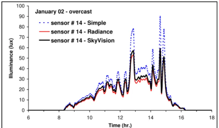
Figures 5 to 8 show a comparison among the three programs: Daylight 1-2-3 (named “SkyVision”), Radiance and Lightswitch (named “Simple”). Simulation results were obtained for typical winter overcast and summer sunny days when the blinds are closed (slat angle = 45o down). Under overcast days,
the new method compares very well with the results of Radiance. Lightswitch , however, produces indoor illuminances 175% higher than Radiance. This difference is due to the fact that the fixed diffuse blinds transmittance of 25% is significantly higher than the actual one, which is 5% (for sky light). Under clear sunny days, again the new method produces indoor illuminances very close to Radiance with a maximum uncertainty lower than 25%. The simple model of Lightswitch also provides acceptable results for the front sensor #1, but under-estimates the results by 30% at the back sensor #14. 0 100 200 300 400 500 600 700 800 6 8 10 12 14 16 18 Time (hr.) Illum inance (lux) sensor # 1 - Simple sensor # 1 - Radiance sensor # 1 - SkyVision January 02 - overcast
Figure 5 Indoor illuminance under a winter overcast day: closed blinds– front sensor #1.
0 10 20 30 40 50 60 70 80 90 100 6 8 10 12 14 16 18 Time (hr.) Illuminance (lux) sensor # 14 - Simple sensor # 14 - Radiance sensor # 14 - SkyVision January 02 - overcast
Figure 6 Indoor illuminance under a winter overcast day: closed blinds– back sensor #14.
0 500 1000 1500 2000 2500 4 6 8 10 12 14 16 18 20 Time (hr.) Illu min a n c e (lu x ) sensor # 1 - Simple sensor # 1 - Radiance sensor # 1 - SkyVision June 06 - sunny
Figure 7 Indoor illuminance under a summer sunny day: closed blinds– front sensor #1.
0 100 200 300 400 500 600 4 6 8 10 12 14 16 18 2 Time (hr.) Illuminance (lux) 0 sensor # 14 - Simple sensor # 14 - Radiance sensor # 14 - SkyVision June 06 - sunny
Figure 8 Indoor illuminance under a summer sunny day: closed blinds– back sensor #14.
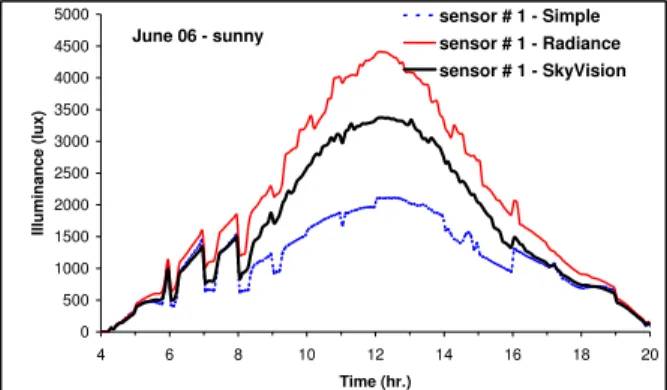
Figures 9 and 10 show another comparison under a typical summer sunny day when the blinds are open (slat angle = 0o). The new method compares overall
well with Radiance, with a maximum difference of lower than 25% occurring at relatively high illuminance values near the window (sensor #1). Far off the window (sensor # 14) where illuminances are usually low (< 1000 lux), the predictions of the new method are even better. Lightswitch, however, under-estimates the indoor illuminance by about
70%, particularly at points far from the window (sensor #14). 0 500 1000 1500 2000 2500 3000 3500 4000 4500 5000 4 6 8 10 12 14 16 18 20 Time (hr.) Illu min a n c e (lu x ) sensor # 1 - Simple sensor # 1 - Radiance sensor # 1 - SkyVision June 06 - sunny
Figure 9 Indoor illuminance under a summer sunny day: open blinds– front sensor #1.
0 200 400 600 800 1000 1200 4 6 8 10 12 14 16 18 2 Time (hr.) Illumina n c e ( lux ) 0 sensor # 14 - Simple sensor # 14 - Radiance sensor # 14 - SkyVision June 06 - sunny
Figure 10 Indoor illuminance under a summer sunny day: open blinds– front sensor #14.
CONCLUSION
This paper developped a general method to compute the daylight coefficients (DC) for dynamic complex fenestration only once during a simulation course. The daylight coeffcients are split into two components: one beam-beam component for the beam-unscattered transmitted light and the second beam-diffuse component for the beam-scattered transmitted light. The beam-beam component of DC depends on the daylight coefficient of a reference clear fenestration and the beam-beam transmittance ratio of the actual and reference fenestration. However, the beam-diffuse component of DC depends not only on the beam-diffuse transmittance ratio, but also on the average daylight coefficient of a hypothetical hemispheric uniform light source sourounding the fenestration’s plane. This method was implemented in Daylight 1-2-3 through the integration of Radiance and SkyVision in its calculation engine. Radiance calculates the daylight coefficients for a reference clear fenestration, and SkyVision modifies the reference DC based on the calculated optical characteristics of the actual
fenestration. This method results in substantial time saving for annual daylighting simulation as the whole set of DC are calculated only once prior to the simulation start. Predictions from the new method for daylight illuminance under overcast and sunny days in a typical office space equiped with a clear window with interior Venetian blinds showed overall good agreement with Radiance explicit calculations.
ACKNOWLEDGMENT
The work was supported by the Panel on Energy Research and Development (PERD), BC Hydro, the National Research Council of Canada, and Natural Resources Canada. The authors are grateful for their contributions and continuous support to the project.
REFERENCES
Bourgeois D, Reinhart C F, Ward G. 2007. “A Standard Daylight Coefficient Model for Dynamic Daylighting Simulations”. Accepted for publication in Building Research & Information.
ISO. 2003. ISO-15099. Thermal performance of windows, doors and shading devices - detailed calculations. International Standard Organisation; Geneva: Switzerland.
Janak M. 1997. “Coupling building energy and lighting simulation”, 5th International IBPSA Conference, Prague, Czech Republic. 313-319. Laouadi, A.; Parekh, A. 2007a. " Optical model of
complex fenestration systems." Accepted for publication in LR&T
Laouadi, A.; Parekh, A. 2007b. "Complex fenestration systems: towards product ratings for indoor environment quality.” Accepted for publication in LR&T.
Mardaljevic J. 2000. “Simulation of annual daylighting profiles for internal illuminance”. LR&T. 32(2):111-118.
NRC. 2006. SkyVision v1.2.1 National Research Council of Canada: http://irc.nrc-cnrc.gc.ca/ie/light/skyvision/
Reinhart C F, Anderson M. 2006. “Development and validation od a RADIANCE model for a translucent panel. Energy & Buildings: 38(7):890-904.
Reinhart C F, Walkenhorst O. 2001. “Dynamic RADIANCE-based Daylight Simulations for a full-scale Test Office with outer Venetian Blinds”. Energy & Buildings: 33(7):683-697. Reinhart C., Bourgeois D., Dubrous F., Laouadi A.,
Lopez P., and Stelescu O. 2007. Daylight 1-2-3 – a state-of-the-art daylighting/energy analysis
software for initial design investigations. Proc. of the 11th IBPSA Buildings Simulation
Conference in Beijing, China.
Reinhart C F, Morrison M, Dubrous F. 2003. “The Lightswitch Wizard - Reliable daylight simulations for initial design investigation”. 8th
International IBPSA Conference, Eindhoven, The Netherlands.. III: 1093-1100. Web site: http://www.sbc.nrcan.gc.ca/software_and_tools/l ightswitch_e.asp
Tregenza P.R. and Waters I.M. 1983. “Daylight Coefficient”. LR&T. 15(2), 65-71.
Tsangrassoulis A., Santamouris M., and Asimakopoulos D. 1966. Theoretical and experimental analysis of daylighting
performance for various shading systems. Energy and Buildings, 24 , pp. 223 – 230.
Vartianen, E. 2000. Daylight Modeling and Optimization of Solar Facades. Ph.D. Thesis From the Faculty of Engineering Physics at the Helsinki University of Technology. http://lib.tkk.fi/Diss/2001/isbn9512253372/
Ward G, Shakespeare R. 1998. “Rendering with RADIANCE. The Art and Science of Lighting Visualization.” Morgan Kaufmann Publishers. WinDat. 2007. WIS v3.01. Window Thermatic
Table 1: Radiance office inputs
Material optical properties Radiance material description
Ceiling 80% diffuse reflectance void plastic Ceiling 0 0 5 0.8 0.8 0.8 0 0 Floor 20% diffuse reflectance void plastic Floor 0 0 5 0.2 0.2 0.2 0 0 Side walls 50% diffuse reflectance void plastic SideWall 0 0 5 0.5 0.5 0.5 0 0 Glazing 80% normal visible transmittance
(transmissivity = 87.15%)
void glass DoubleGlazing 0 0 3 0.8715 0.8715 0.8715 Diffuse blinds 70% diffuse reflectance void plastic BlindSlats 0 0 3 0.7.7 0.7 0 0
Table 2: Radiance simulation parameters Ambient bounces Ambient division Ambient sampling Ambient accuracy Ambient resolution Direct threshold Direct sampling 7 1500 100 0.1 200 0 0