Publisher’s version / Version de l'éditeur:
Vous avez des questions? Nous pouvons vous aider. Pour communiquer directement avec un auteur, consultez la première page de la revue dans laquelle son article a été publié afin de trouver ses coordonnées. Si vous n’arrivez Questions? Contact the NRC Publications Archive team at
[email protected]. If you wish to email the authors directly, please see the first page of the publication for their contact information.
https://publications-cnrc.canada.ca/fra/droits
L’accès à ce site Web et l’utilisation de son contenu sont assujettis aux conditions présentées dans le site LISEZ CES CONDITIONS ATTENTIVEMENT AVANT D’UTILISER CE SITE WEB.
Client Report (National Research Council of Canada. Construction), 2015-01-30
READ THESE TERMS AND CONDITIONS CAREFULLY BEFORE USING THIS WEBSITE.
https://nrc-publications.canada.ca/eng/copyright
NRC Publications Archive Record / Notice des Archives des publications du CNRC : https://nrc-publications.canada.ca/eng/view/object/?id=608b495d-f7a6-4c9e-8297-1c8a2420286f https://publications-cnrc.canada.ca/fra/voir/objet/?id=608b495d-f7a6-4c9e-8297-1c8a2420286f
NRC Publications Archive
Archives des publications du CNRC
For the publisher’s version, please access the DOI link below./ Pour consulter la version de l’éditeur, utilisez le lien DOI ci-dessous.
https://doi.org/10.4224/21277597
Access and use of this website and the material on it are subject to the Terms and Conditions set forth at
Fire demonstration: cross-laminated timber stair/elevator shaft
Su, Joseph Z.; Muradori, Saša
Client Report: A1-006010.1
NATIONAL RESEARCH COUNCIL CANADA
Fire Demonstration
–
Cross-Laminated Timber Stair/Elevator Shaft
For
FPInnovations
Fire Demonstration –
Cross-Laminated Timber Stair/Elevator Shaft
Author:
Joseph Z. Su, Ph.D. and Saša Muradori
Quality Assurance:
Gary D. Lougheed, Ph.D.
Approved:
Cameron McCartney
Program Leader
Mid-Rise Wood Buildings, NRC-Construction
Report No: A1-006010.1
Report Date: January 30, 2015
Contract No: A1-006010
Program: Mid-Rise Wood Buildings
50 pages
This report may not be reproduced in whole or in part without the written consent of the National Research Council Canada and the Client.
Table of Contents
1 INTRODUCTION ...1
2 OBJECTIVES OF THE FIRE DEMONSTRATION...1
3 CONTEXT OF THE FIRE DEMONSTRATION...1
4 LARGE-SCALE FIRE DEMONSTRATION...2
4.1 Large-Scale Fire Demonstration Setup ...2
4.1.1 Construction of Stair/Elevator Shaft ...8
4.1.2 Construction of Apartment Unit – The Fire Compartment...9
4.1.3 Structural Load ...12
4.1.4 Fuel Load and First Item Ignited...12
4.1.5 Instrumentation ...15
4.2 Procedure ...21
4.3 Results from Large-Scale Fire Demonstration...21
4.3.1 Fire Development in the Apartment...21
4.3.2 Encapsulation Time and Performance of CLT Structure ...29
5 SUMMARY ...42
6 CONCLUSIONS...46
7 ACKNOWLEDGMENTS...46
8 REFERENCES ...46
List of Tables
Table 1. Results of Survey on Residential Fire Load Densities for Various Rooms ...13Table 2. Encapsulation Time (min) – Time to Reach Temperature Rise Criteria ...30
List of Figures
Figure 1. Schematic of large-scale fire demonstration setup. ...2Figure 2. Plan view of the large-scale fire demonstration setup...3
Figure 3. Vertical view: cross section A……..….…….. ...4
Figure 4. Vertical view: cross section B……...4
Figure 5. Vertical view: cross section C...5
Figure 6. Details of components for CLT wall and ceiling assemblies. ...6
Figure 8. Interior of the stair/elevator shaft. ...8
Figure 9. Components of the shared wall in the fire compartment. ...10
Figure 10. Components of the ceiling assembly in the fire compartment. ...11
Figure 11. Illustration of fuel arrangement in the fire compartment...14
Figure 12. Photographs of fuel arrangement in the fire compartment. ...15
Figure 13. Instrumentation inside the stair/elevator shaft. ...16
Figure 14. Thermocouples installed at interfaces across TYPE-2 and TYPE-4 walls (birds eye view). ...18
Figure 15. Thermocouples installed at interfaces across TYPE-2 wall and ceiling assembly (vertical view)...19
Figure 16. Thermocouples installed at interfaces across TYPE-4 wall and ceiling assembly (vertical view)...20
Figure 17. Ignition of the upholstered loveseat followed by flashover at 2 min 35 s...21
Figure 18. Video graphic captures of fire development (0-4 min)...23
Figure 19. Video graphic captures of fire development (5-30 min)...24
Figure 20. Video graphic captures of fire development (35-60 min)...25
Figure 21. Video graphic captures of fire development (65-90 min)...26
Figure 22. Video graphic captures of fire development (95-120 min)...27
Figure 23. Temperatures at 0.6 m, 1.6 m and 2.6 m heights measured using the two thermocouple trees (TC1 and TC2) in the apartment. ...28
Figure 24. Thermocouples at interfaces in the apartment ceiling assembly at ¼, ½ and ¾ of length and width...31
Figure 25. Temperatures at various interfaces in the apartment ceiling assembly...32
Figure 26. Thermocouples at various interfaces in TYPE-2 wall of the apartment at ¼, ½ and ¾ of length and height...34
Figure 27. Temperatures at various interfaces in TYPE-2 wall assembly of the apartment...35
Figure 28. Double layer of gypsum board and rigid mineral wool fibre insulation remained on the apartment wall until end of demonstration. ...36
Figure 29. Thermocouples at various interfaces in the wall assembly shared by the stair/elevator shaft and apartment at ¼, ½ and ¾ of width and height. ...38
Figure 30. Temperatures at various interfaces in the wall assembly shared by the apartment and stair/elevator shaft...39
Figure 31. Temperatures, differential pressure and optical density in the shaft. ...41
Figure 32. Inside of the fire compartment after the fire demonstration...44
Figure 33. Outside of the demonstration structure and inside of the stair/elevator shaft after the fire demonstration. ...45
FIRE DEMONSTRATION –
Cross-Laminated Timber Stair/Elevator Shaft
Joseph Z. Su, Ph.D. and Saša Muradori
1 INTRODUCTION
The consortium of Nordic Wood Structures, EBC and Yvan Blouin Architect are designing a 13-storey residential building using a mass timber structure. The project, named "Origine" is proposed to be located in the eco-neighbourhood of Pointe-aux- Lièvres in Quebec City and to start construction in spring 2015.
The mass timber structure would be composed primarily of glue-laminated timber and cross-laminated timber (CLT). The cross-cross-laminated timber consists of at least three orthogonally bonded layers of solid-sawn lumber that are laminated by gluing of longitudinal and transverse layers with structural adhesives to form a solid rectangular-shaped, straight and plane timber intended for floor, roof or wall applications.
The National Research Council Canada (NRC) was requested to assist in the demonstration of an alternative solution to noncombustible construction as prescribed in the Québec Construction Code [1] and the National Building Code of Canada (NBCC) [2]. Three series of fire tests were conducted at NRC to investigate: the fire endurance (fire resistance) of CLT floor and wall assemblies [3], the fire performance of a CLT exterior wall assembly [4], and the fire
demonstration of a CLT stair/elevator shaft for the proposed building. This report provides the description and results of the fire demonstration for the CLT stair/elevator shaft. This fire
demonstration was funded by the Government of Quebec’s Ministère des Forêts, de la Faune et des Parcs through FPInnovations.
2 OBJECTIVES OF THE FIRE DEMONSTRATION
The main objective of the fire demonstration was to observe the performance of a cross-laminated-timber stair/elevator shaft, which was adjacent to an apartment under a severe fire, as an alternative solution to a shaft of noncombustible construction for the proposed wood building.In addition, data on fire severity, spread of smoke and the integrity of the building systems was collected.
3 CONTEXT OF THE FIRE DEMONSTRATION
The installation of automatic sprinkler systems is mandatory in all buildings taller than six storeys [1, 2]. Automatic sprinklers are highly effective in controlling or suppressing fires where fires are large enough to activate the sprinklers. The performance effectiveness of sprinklers is over 91% for residential occupancies [5]. The primary benefits of sprinkler systems are a
reduction in the extent of fire growth and spread resulting in reduced losses of life and property. Comprehensive information on these aspects regarding the performance effectiveness of automatic sprinkler systems is documented in References [5-7].
The fire demonstration under this project was conducted without sprinklers and therefore did not take the effectiveness of sprinklers in controlling or suppressing the fire into account. The
demonstration simulated one of the worst case scenarios where sprinklers might fail to operate or control the fire.
4 LARGE-SCALE FIRE DEMONSTRATION
The large-scale fire demonstration was conducted to observe and validate the fire safety performance of a mass timber stair/elevator shaft.The fire demonstration was conducted on November 27, 2014 at NRC’s large-scale fire test facility in Mississippi Mills, ON, and was witnessed by building and fire safety authorities and various parties involved or interested in the
"Origine" project.
4.1 Large-Scale Fire Demonstration Setup
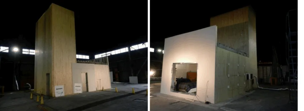
A large-scale setup was constructed to represent a section of the proposed 13-storey residential building of mass timber construction. This involved construction of a 9-meter high stair/elevator shaft and an adjacent apartment unit using CLT structural panels which conformed to ANSI/APA PRG-320 standard [8]. The dimensions of the setup resembled the actual size of the building section of interest.
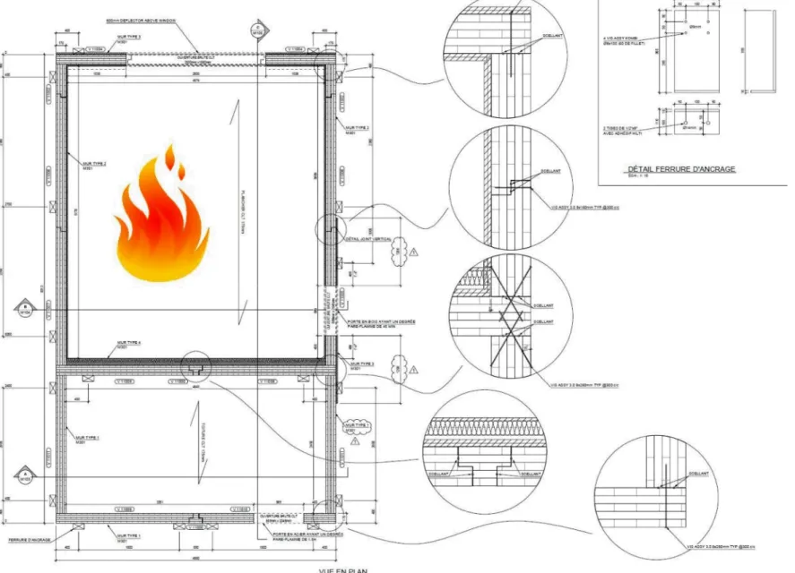
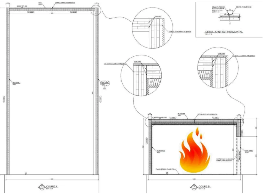
Figure 1 shows a schematic of the setup. Figure 2 to Figure 6 show construction details of the setup. Figure 7 shows photographs of the setup. A description of the structural assemblies and their arrangement is provided in the following sections.
4.1.1 Construction of Stair/Elevator Shaft
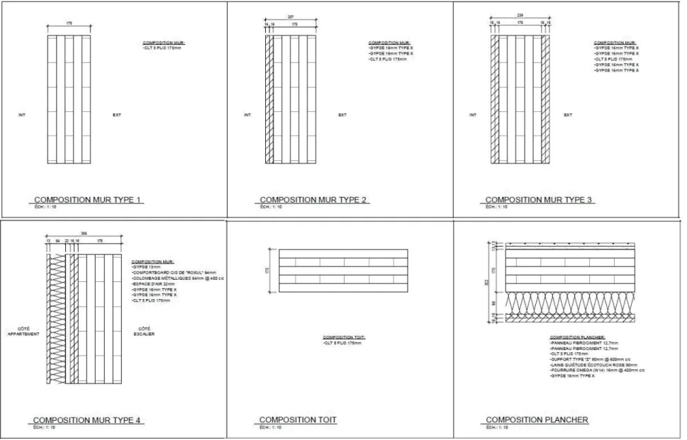
The walls and ceiling of the stair/elevator shaft were built using 5-ply, 175 mm thick CLT panels. The stair/elevator shaft walls were anchored to the concrete floor slab in the test facility. The outside dimension of the stair/elevator shaft was 4.99 m wide x 2.80 m deep x 9.00 m high and the inside dimension was 4.64 m wide x 2.45 m deep x 8.83 m high. The footprint was the
actual area of the stair/elevator shafts of the "Origine" project, while the height was equivalent to three storeys (3 m each). There was a door having a fire-protection rating of 45 min in the
stair/elevator shaft, which was closed during the demonstration.
It was assumed that a fire that originated in the adjacent apartment unit would have little effect on the CLT shaft and would not penetrate through the CLT panels into the shaft during the fire demonstration. Therefore, the CLT panels were left fully exposed on the inside (see Figure 8) and outside (see Figure 7) of the stair/elevator shaft to reduce its construction time and to allow better observation of any fire impact on the CLT panels. It should be noted that the actual design for the “Origine” project includes two layers of 16 mm (5/8”) thick Type X gypsum board on the interior side of the walls of the stair/elevator shaft.
To compensate the lacking of gypsum board on the CLT panels in the shaft in this fire
demonstration setup and to prevent smoke from potentially leaking to the shaft because of the lacking, a common construction adhesive was used as the sealant at the joints of the CLT panels for the shaft as shown in Figure 2and Figure 3.
4.1.2 Construction of Apartment Unit – The Fire Compartment
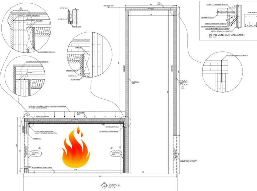
A fire compartment, representing a studio apartment unit, was built next to the stair/elevator shaft, using 175 mm thick 5-ply CLT structural panels for the walls and ceiling. The apartment shared a wall with the stair/elevator shaft. The other three walls were anchored to the concrete floor slab in the test facility. The ceiling panels were supported by ledgers installed on the wall shared with the shaft and on the opposite wall of the apartment. The ledgers were made of 24F-ES/NPG grade glulam and had a cross section of 86 mm x 267 mm.
A fire-rated caulking was used as the sealant in the apartment (fire room) at the CLT panel-to-panel joints for the walls and ceiling and at the CLT panel-to-panel-to-ledger joints as shown in Figure 2, Figure 4 and Figure 5, except the shared wall with the shaft where the CLT panel-to-panel joints were sealed using the common construction adhesive as mentioned in Section 0. The purpose of using the sealants was to compensate for eliminating gypsum board on most surfaces
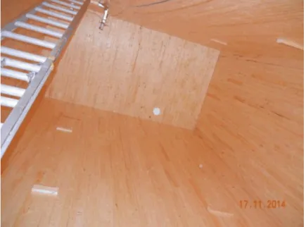
outside the apartment in this fire demonstration setup in order to prevent smoke from potentially leaking through the joints because of the elimination of gypsum board on the outside.However, the horizontal spline connection of the two CLT ceiling panels in the middle (see Figure 4) was joined on the top side (unexposed to fire) with strips of 12 mm thick, 120 mm wide plywood glued with two 6-mm wide lines of a construction adhesive and nailed on each side of the panels every 50 mm with common 76-mm nails.
There was a rough window opening (without installation of a real window) in the wall opposite the stair/elevator shaft toprovide ventilation air for the fire in the apartment. The size of the opening was 2.50 m wide x 1.88 m high, which was a size of windows commonly used in
multi-unit residential buildings. A door with a 45 minute fire-protection rating was installed in one wall. The door was closed during the demonstration.
The finished apartment, as described in the following sections, measured 4.58 m wide x 5.18 m deep x 2.70 m high. The range of 5.18 m is the actual span range of a floor adjacent to the stair/elevator shaft in the "Origine" project. All assemblies meet the 2-h fire resistance rating required by the NBCC for all buildings taller than six storeys.
4.1.2.1 Fire Compartment Inside Finishes
4.1.2.1.1 Wall Interior Finish
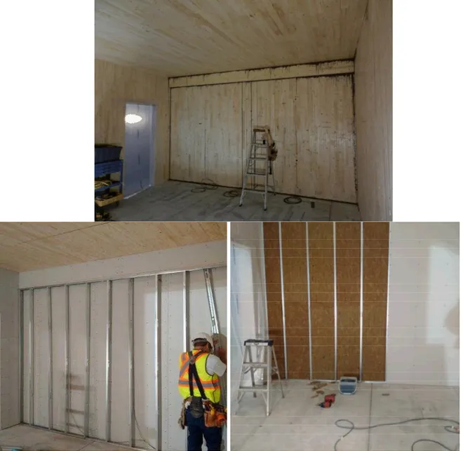
The interior finish was first applied to the interior side of the walls. All the CLT wall surfaces inside the apartment (including the ledgers) were protected using two layers of 16 mm (5/8”) thick Type X gypsum board. The two layers of gypsum board were directly applied to the CLT wall panels in a staggered fashion. The gypsum boards were attached to the CLT wall panels with 51 mm (2″) long type S screws spaced at 300 mm on centre, starting at 150 mm from the edges of the assembly for the first (or base) layer and 200 mm from the edges for the second (or face) layer. Screws were placed at a minimum distance of 38 mm (1½″) from the edges of all gypsum board sections. On the face layer only, joints between board sections were covered with tape and joint compound and all screw heads were covered with joint compound.
For the wall shared with the stair/elevator shaft, additional components including
noncombustible rigid mineral wool fibre insulation were added to this shared wall on the apartment side to meet the code requirements for sound insulation [1, 2]. The additional
components included a lightweight steel stud frame that was added to the shared wall after the CLT panels and glulam ledger were lined with two layers of 16 mm thick Type X gypsum board. The steel studs were 64 mm deep and spaced at 400 mm on centre. A 22-mm air gap was kept between the steel stud frame and the gypsum board-lined wall such that the gypsum board-lined ledger was flush with the steel frame (see Figure 9). The cavity formed by the steel studs was filled with 64 mm thick rigid mineral wool fibre insulation. A layer of 13 mm (1/2”) thick regular gypsum board was installed on the ledger and the lightweight steel frame with 32 mm (1-1/4″) long type S screws spaced at 300 mm on centre, starting at 150 mm from the edges of the assembly. Screws were placed at a minimum distance of 38 mm (1½″) from the edges of all gypsum board sections. Joints between the gypsum board sections were covered with tape and joint compound and all screw heads were covered with joint compound. Figure 9 shows the components of the shared wall in the fire compartment.
4.1.2.1.2 Ceiling Finish
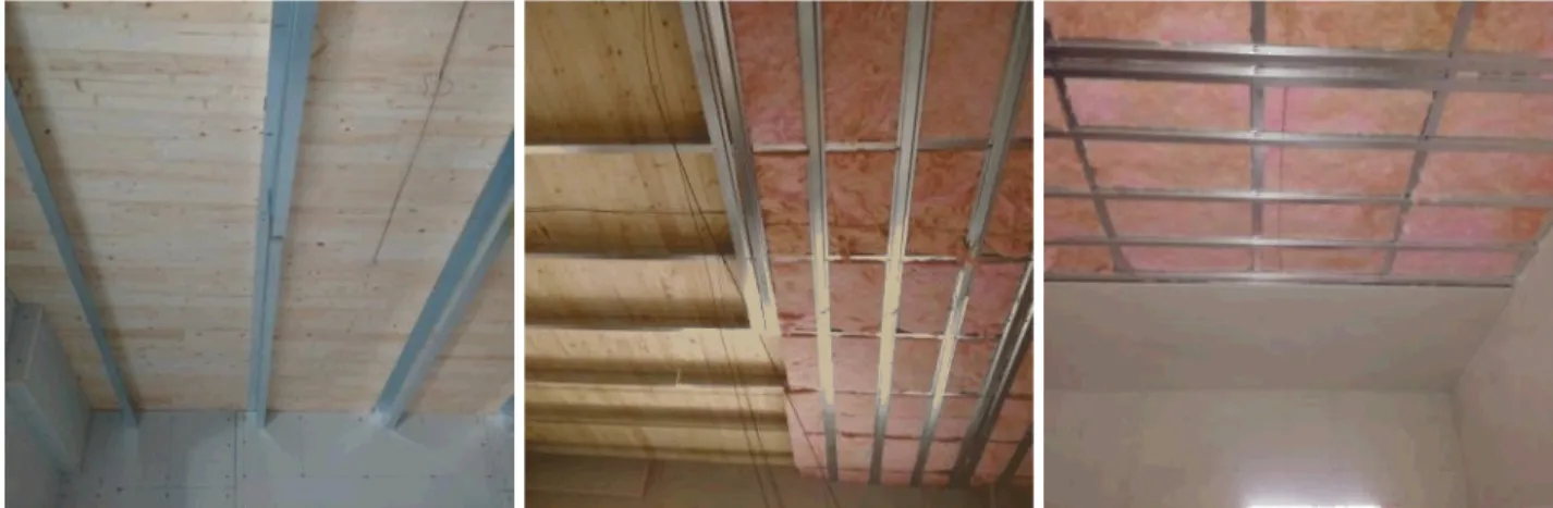
The ceiling finish was applied after all the interior wall surfaces were lined. 90 mm deep 26-gauge galvanized steel Z channels were installed below the CLT ceiling panels. The Z-channels were installed perpendicular to the ceiling span direction and were spaced at 600 mm on centre. The Z channels were fastened to the CLT panels with 38 mm (1 ½″) long wood screws of size 8. The screws were spaced at 300 mm on centre.
16 mm (⅝″) deep furring strips made of 25-gauge galvanized steel were installed perpendicular to the Z-channels and were spaced at 400 mm on centre. The furring strips were fastened to the Z channels using 25 mm (1″) pan head self-tapping metal screws of size 6. The screws were spaced 600 mm apart on each side of the furring strips. Double furring strips were used every 1200 mm to facilitate the subsequent installation of gypsum board. The space between the Z channels and behind the furring strips was filled with 90 mm thick noncombustible fiberglass insulation.
A single layer of 16 mm (5/8”) thick Type X gypsum board was attached to the metal furring strips, covering the fiberglass insulation. The gypsum board was attached using 32 mm (1 ¼″) long type S screws spaced at 300 mm on centre starting at 150 mm from the edges of the assembly. Screws were placed at a minimum distance of 38 mm (1½″) from the edges of all gypsum board sections, which was accommodated with the use of the double furring strips at the gypsum joints. Joints between board sections were covered with tape and joint compound. All screw heads were covered with joint compound.Figure 10 shows the components of the ceiling assembly in the fire compartment.
Figure 10. Components of the ceiling assembly in the fire compartment.
4.1.2.1.3 Floor Finish
A floating laminated floor with an acoustic underlay was installed on the concrete floor slab in the apartment.
4.1.2.2 Fire Compartment Outside Finishes
As shown in Figure 7, most CLT wall surfaces outside the fire compartment were not protected, except for limited surface areas surrounding the rough window opening and the door where two layers of 16 mm thick Type X gypsum board were installed. The edges of the window opening were also lined with two layers of 16 mm thick Type X gypsum board and covered with
galvanized steel sheets.
On the top of the apartment, the CLT ceiling panels were covered with two staggered layers of 13 mm (1/2”) thick cement board. The cement board panels were fastened to the CLT panels with 51 mm (2″) long wood screws of size 8. Screws were spaced 610 mm apart starting 19 mm (¾″) from the edge of the cement board.
4.1.3 Structural Load
The total specified load of the ceiling assembly is 5.69 kPa including a self-weight of 1.49 kPa for the cross-laminated timber slab. The specified load consists of a dead load of 3.79 kPa and a live load of 1.9 kPa.
For the fire demonstration, concrete blocks were placed above the CLT ceiling assembly and, along with the self-weight of the whole assembly, induced a specified load of 4.74 kPa to
replicate a design fire loading condition of one half of the live load plus the dead load (0.5L + D) as per paragraph A-25 in Commentary A of User's Guide – NBC 2010: Structural Commentaries (Part 4 of Division B) [9].
4.1.4 Fuel Load and First Item Ignited
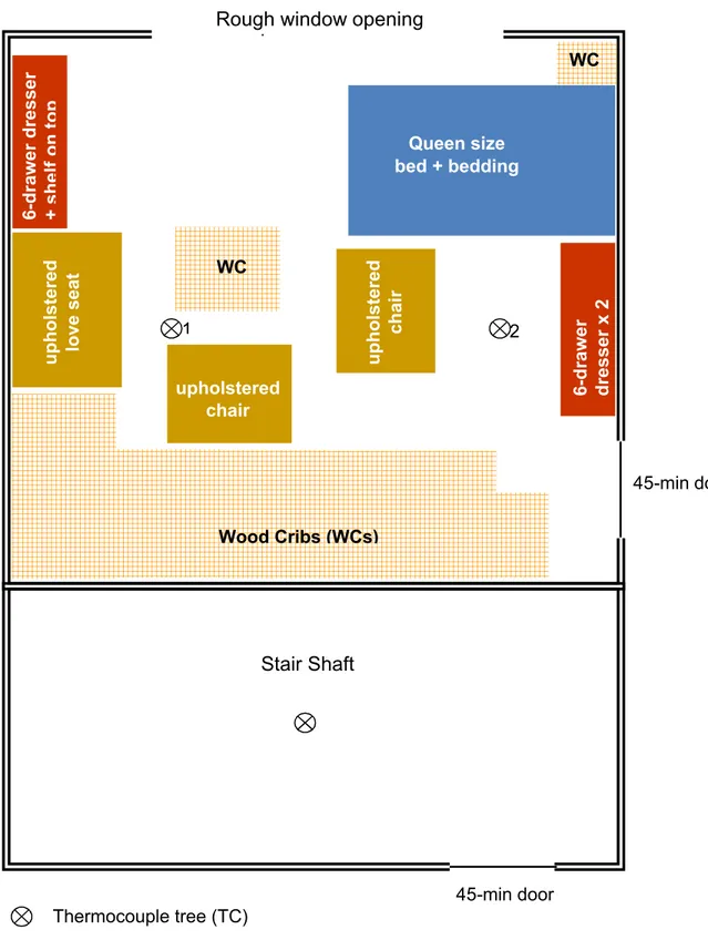
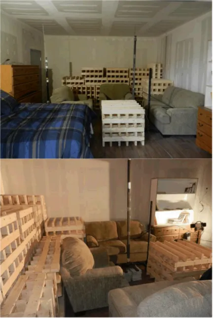
The fire compartment was constructed to simulate a studio apartment with sleeping, living and kitchen areas. The fuel load consisted of a queen size bed with mattress and box spring, upholstered chairs and loveseat (2-seat sofa), dressers, bookshelf and wood cribs. The wood cribs simulated night, coffee and dining tables, kitchen cabinets and counters. The first item ignited was the upholstered loveseat.Figure 11 illustrates the fuel arrangement in the apartment.Figure 12shows photographs of fuel arrangement in the fire compartment. The fire load density (FLD) in the apartment was 790 MJ/m2. A survey on residential fire load
determined a range of FLD for various rooms in residences as shown inTable 1[10].Since the
studio apartment used in the demonstration combined sleeping, living and kitchen areas, the FLD of 790 MJ/m2used in the demonstration was comparable tothe average 95thpercentile
Table 1. Results of Survey on Residential Fire Load Densities for Various Rooms Room Mean FLD (MJ/m2) Standard Deviation (MJ/m2) Minimum (MJ/m2) Maximum (MJ/m2) 95th Percentile (MJ/m2) Kitchen 807 123 420 1244 940 Secondary Bedroom 594 146 107 1000 846 Primary Bedroom 534 125 249 920 753 Living Room 412 127 106 897 610 Dining Room 393 132 119 901 576 Average 745
Figure 11. Illustration of fuel arrangement in the fire compartment. 2 1 Wood Cribs (WCs) 6 -drawer dresser x 2 6 -drawer dresser + shelf on top upholstered chair upholstered love seat
WC
Queen size bed + bedding
Rough window opening
opening
45-min doorStair Shaft
WC upholstered chair Thermocouple tree (TC) 45-min doorFigure 12. Photographs of fuel arrangement in the fire compartment.
4.1.5 Instrumentation
4.1.5.1 Instrumentation in Stair/Elevator Shaft
Fresh air was supplied to the stair/elevator shaft to maintain pressurization of 12 Pa in the shaft. This is the design pressurization for both the stair shaft and elevator shaft in the "Origine" project. The actual pressurization was monitored during the fire demonstration.
An array of nine thermocouples was installed at the center of the stair/elevator shaft at one meter intervals along the 9-m height starting 1 m above the floor to measure the temperature at the different heights. There were also nine thermocouples covered with pads used in standard fire resistance tests [11] on the unexposed side of the CLT wall section adjacent to the
apartment.
An optical density meter was installed in the stair/elevator shaft at the 7 meter height to monitor if any smoke leaked into the shaft during the demonstration. Figure 11and Figure 13 show the instrumentation inside the stair/elevator shaft.
Figure 13. Instrumentation inside the stair/elevator shaft. optical density meter
4.1.5.2 Instrumentation for Fire Compartment
As shown inFigure 11and Figure 12, two thermocouples trees, each with three thermocouples (shielded for radiation) at heights of 0.6 m, 1.6 m and 2.6 m, were located in the apartment to measure room temperatures.
Thermocouples were installed at various interfaces across the CLT wall and ceiling assemblies to measure temperatures at the interfaces between materials. Figure 14, Figure 15 and Figure 16 illustrate the location of the thermocouples installed at the interfaces across the wall and ceiling assemblies.
Twenty seven thermocouples were installed at the interfaces across the shared wall between the apartment and stair/elevator shaft (TYPE 4 wall in the drawings). As shown in Figure 14 and Figure 16, nine thermocouples were installed on the 16 mm thick Type X gypsum board face layer at the interface with the air gap behind the lightweight steel frame, nine thermocouples were installed at interface between the base layer of gypsum board and the CLT on the apartment side, and nine thermocouples covered with pads used in standard fire resistance tests were installed on the shaft side of the CLT. The thermocouples were positioned at quarter and mid points of the assembly in the horizontal and vertical directions.
Twenty seven thermocouples were installed at the interfaces across the ceiling assembly. As shown inFigure 15 and Figure 16nine thermocouples were installed above the gypsum board on the metal furring strips, nine thermocouples were installed at the interface between the insulation and CLT, and nine thermocouples covered with pads used in standard fire resistance tests were installed on the top of the ceiling assembly. The thermocouples were positioned at quarter and mid points of the ceiling assembly in the two horizontal directions perpendicular to each other.
Eighteen thermocouples were installed at the interfaces across the TYPE 2 wall assembly that had no door. As shown in Figure 14 and Figure 15, nine thermocouples were installed at
interface between the gypsum board based layer and the CLT, and nine thermocouples covered with pads used in standard fire resistance tests were installed on the exterior surface of the CLT. The thermocouples were positioned at quarter and mid points of the wall assembly in horizontal and vertical directions.
4.2 Procedure
The following procedure was followed.
1. Ignite the loveseat with a square burner in accordance with ASTM E1537 [12]; 2. Let the fire continue for 2 hours;
3. End the demonstration by extinguishing the fire after 2 hours; and, 4. Observe after fire extinguishment.
4.3 Results from Large-Scale Fire Demonstration
4.3.1 Fire Development in the Apartment
The loveseat was ignited using a square burner in accordance with the ASTM E1537 [12] protocol. Smoke started to issue through the rough window opening at 30 s. Flames started to issue through the rough window opening at 2 min 20 s. Flashover occurred at 2 min 35 s. A high-intensity fast growing fire was produced in the apartment. Figure 17 shows the ignition of the loveseat and the flashover of the apartment.
Figure 17. Ignition of the upholstered loveseat followed by flashover at 2 min 35 s. Figure 18 to Figure 22 are video graphic captures of the fire development during the fire demonstration. The video indicated that, after flashover, fresh air mostly entered the fire compartment at the right half of the rough window opening and the fire plume mostly exited at the left half of the opening.
At approximately 15 min, the fire appeared to start involving the CLT ceiling panels with the fire plume exiting at the upper portion of the opening and fresh air entering at the lower portion of the opening. The gypsum board on the ceiling also appeared to fall piece by piece after 15 min. The upholstered furniture and mattress were completely consumed by 20 min.
At 30 min, the entire steel Z channels and metal furring strips fell off the ceiling and knocked over the two thermocouple trees. The CLT ceiling panels were fully involved in the fire and contributed to the fire plume that issued through the opening.
From 40 to 60 min, the fire plume that issued from the opening reduced in intensity. This could be due to the char layer formed on the ceiling CLT surface that slowed down the burning of the CLT panels on the ceiling. During this period, the wood cribs located in the apartment reduced to a pile of glowing debris on the floor. Some charred pieces started to fall from the CLT ceiling. At approximately 60 min, many pieces of char fell from the CLT ceiling and more vigorous
burning occurred on the ceiling, indicating the fall off of the charred first ply and involvement of the second ply of the uncharred CLT ceiling panels. The fire plume through the opening increased in size.
From 75 to 90 min, most of the fuel load was consumed and the fire gradually reduced in size. The fire plume through the openingalso decreased.
After 90 min, no fire plume issued through the opening. The fire in the apartment continued to decrease in size until the end of the fire demonstration.
The fire demonstration was ended shortly after 120 min. This duration was chosen in advance by the parties involved in planning the fire demonstration, considering that floor and loadbearing wall assemblies for any building taller than six storeys are required by the NBCC to meet a 2-h fire resistance rating although this fire demonstration was not a standard fire resistance test. The fire was extinguished using a firefighting water hose. The double layers of Type X gypsum board stayed on the walls throughout the fire demonstration until the fire extinguishment operation. The mineral wool insulation also stayed on the shared wall with the stair/elevator shaft.
Figure 18. Video graphic captures of fire development (0-4 min). 0:00 1:00 4:00 3:00 2:35 2:00
Figure 19. Video graphic captures of fire development (5-30 min). 5:00 30:00 25:00 15:00 20:00 10:00
Figure 20. Video graphic captures of fire development (35-60 min). 35:00 40:00 60:00 55:00 50:00 45:00
Figure 21. Video graphic captures of fire development (65-90 min). 70:00 65:00 90:00 80:00 75:00 85:00
Figure 22. Video graphic captures of fire development (95-120 min). 95:00 120:00 115:00 100:00 105:00 110:00
Figure 23 shows the temperatures measured in the apartment by the thermocouples located on the two thermocouple trees. The temperatures were uniform with height in the upper portion of the room (the temperature at the 2.6 m height was similar to the temperature at the 1.6 height). However, the fire did not develop uniformly throughout the entire area, as is illustrated in the figure.
Peak temperatures of 1000-1100C were reached by 10 min during the demonstration. After 10 min, the temperatures stayed at or above 1000C in the upper portion of the apartment. Unfortunately at 30 min, the two thermocouple trees were knocked down to the floor by the fall of the entire steel Z channels and metal furring strips installed as part of the ceiling system. After 30 min, the exact locations of the thermocouples became uncertain. In some cases, the thermocouples could be buried under the debris, and the temperatures shown in Figure 23are mostly indicative of the temperatures in the lower portion of the apartment. Nevertheless, the general trend of these temperature measurements is consistent with the graphic captures (Figure 18to Figure 22) of the fire development.
Time (min)
0 10 20 30 40 50 60 70 80 90 100 110 120T
em
pe
ra
tu
re
(
oC
)
0 200 400 600 800 1000 1200 1400 TT1 - 2.6 m TT1 - 1.6 m TT1 - 0.6 m TT2 - 2.6 m TT2 - 1.6 m TT2 - 0.6 m S101 PRF-03Figure 23. Temperatures at 0.6 m, 1.6 m and 2.6 m heights measured using the two thermocouple trees (TT1 and TT2) in the apartment.
Also shown in Figure 23 is the standard CAN/ULC-S101 time-temperature curve used in fire-resistance tests [11]. The peak temperatures in the apartment were much higher than the standard time-temperature curve used in fire-resistance tests. For the first hour of the
demonstration, the fire in the apartment was more severe than the standard fire used in fire-resistance tests, providing a severe challenge to the structure. After 75 min, the temperatures
After 30 min, exact locations of the thermocouples are uncertain due to the fall of thermocouple trees
measured at all locations continuously decreased and the fire was contained within the room boundaries until the end of the demonstration.
Figure 23 also shows a time-temperature curve derived from a previous fire test (PRF-03) in a fully furnished bedroom of noncombustible construction as part of a project to develop data for establishing design fires for multi-suite residential occupancies [13]. The PRF-03 curve was the average ceiling temperature in that bedroom. The ceiling temperature profiles measured in the studio apartment in this fire demonstration were similar to, but higher in the initial 15 min than, the PRF-03 curve.
4.3.2 Encapsulation Time and Performance of CLT Structure
An encapsulation approach can be used to protect the combustible structural materials in tall wood buildings as an alternative solution to meet the intent of the noncombustibility requirement [
7
, 14-15]. The effectiveness of encapsulation materials as a protective cover to protectcombustible structural materials has been demonstrated in bench-, intermediate- and full-scale fire tests conducted by NRC under other research projects [7].
In this fire demonstration, gypsum board and noncombustible insulation were used as the encapsulation materials to protect the CLT structural materials in order to delay or even prevent the effects of the fire on the CLT structural elements and especially on the CLT shaft structure. In this way, the ignition of the CLT structure and any subsequent contributions from the
combustible structural elements to fire severity can be delayed or avoided.
Temperature profiles at the CLT interface on the side exposed to the fire were used to determine the encapsulation time for the protection of the CLT wall and ceiling panels. The times at which the temperature rise values at the interface exceeded the following criteria were determined as the encapsulation times [16]:
The average temperature rise value over the whole surface is limited to 250ºC; and
The maximum temperature rise value at any point on that surface does not exceed 270ºC. These criteria are based on the temperature at which wood-based products begin to char (approximately 300ºC) [16-17]. At lower temperatures, fires would not affect the structural elements and there would be no gasification or pyrolysis of the wood. It is assumed that a protective cover will be effective as long as the average temperature rise value over the exposed surface of the protected building element is limited to 250ºC, and the maximum
temperature rise value at any point on that surface does not exceed 270ºC. The criteria provide conservative, technically-based estimates for evaluating the performance of an encapsulation system.
Table 2 summarizes the times at which the temperature rise values exceeded the specific criteria for each assembly. These encapsulation times are for the severe non-standard fire exposure conditions used in this fire demonstration. The encapsulation time would be different for different fire exposure such as the standard time-temperature curve from CAN/ULC-S101.
Table 2. Encapsulation Time (min) – Time to Reach Temperature Rise Criteria Assembly - interface averageT=250C single point T=270C Ceiling - insulation and CLT surface 15.7 15.2
TYPE-2 Wall (not shaft wall) - base layer GB and CLT surface 60.9 56.9 TYPE-4 Shaft Wall - base layer GB and CLT surface DNR (<210°C) 91.00
GB – gypsum board DNR – Did not reach temperature rise criteria.
4.3.2.1 Performance of CLT ceiling assembly in the fire apartment
The CLT ceiling panels were protected using a single layer of 16 mm thick Type X gypsum board and 90 mm thick fiberglass insulationmounted to the steel furring strips and Z channels.
Figure 24illustrates the thermocouples installed, and Figure 25 shows the temperature profiles measured, at various interfaces in the ceiling assembly.
The temperatures measured using the nine thermocouples installed above the gypsum board on the furring strips show that heat transfer through the gypsum board follows a typical three-stage pattern: an initial phase with the temperatures rising to approximately 100C; a second phase with steady temperatures at approximately 100C during the calcination of the gypsum board; a third phase with a more rapid temperature increase. The temperature rise value reached 270C at a single point at 12.2 min and 250C on average at 12.9 min.
The temperatures measured using the nine thermocouples installed at the interface between the insulation and CLT were similar to those measured on the furring strips. The encapsulation time for the CLT ceiling panels was 15.2 min based on a single point temperature rise or 15.7 min on the average temperature rise for the nine thermocouples. After these times, visual observation and the temperature profiles indicated fall off of the ceiling gypsum board. After 16 min, the ceiling CLT panels became involved in the fire but there was no flame penetration through the CLT panels during the 2 h demonstration.
It was observed after the demonstration that two plies of the CLT ceiling panels were charred and consumed in the fire, but fell off after applying the water hose stream to extinguish the fire. The remaining plies of the CLT ceiling panels were not significantly affected by the fire. The third ply charred at some locations, but remained mostly unaffected.
The nine thermocouples covered with pads used in standard fire resistance tests on the top of the ceiling assembly show less than 6°C temperature rise except the thermocouple located at the center of the ceiling assembly which measured a temperature rise of 46°C. (Note that the horizontal spline connection of the CLT ceiling panels in the middle was joined with strips of plywood glued with a construction adhesive.) All the temperature rises were well below the 140°C average and 180°C single point temperature increases prescribed in CAN/ULC-S101 [11].
Figure 24. Thermocouples at interfaces in the apartment ceiling assembly at ¼, ½ and ¾ of length and width.
Time (min) 0 10 20 30 40 50 60 70 80 90 100 110 120 T em pe ra tu re ( o C ) 0 200 400 600 800 1000 1200 1400 NE EC SE NC C SC NW WC SW Time (min) 0 10 20 30 40 50 60 70 80 90 100 110 120 T em pe ra tu re ( o C ) 0 200 400 600 800 1000 1200 1400 Time (min) 0 10 20 30 40 50 60 70 80 90 100 110 120 T em pe ra tu re ( o C ) 0 20 40 60 80 100
above ceiling gypsum board on furring strips
between fiberglass insulation and CLT surface
thermocouple C as shown in Figure 24 outside on top of ceiling assembly
4.3.2.2 Performance of three CLT wall assemblies (TYPE 2 and TYPE 3) in the fire apartment The three wall assemblies that were not part of the stair/elevator shaft were protected using a double layer of 16 mm thick Type X gypsum board directly attached to the interior side of the CLT wall panels.
Figure 26illustrates the thermocouples installed, and Figure 27 shows the temperature profiles measured at various interfaces in the wall assembly.
The temperatures measured using the nine thermocouples installed at the interface between the base layer of gypsum board and the CLT panels also show a three-stage heat transfer process through the gypsum board with an initial temperature rise to 100C, the gypsum calcination at a steady temperature of 100C and a more rapid temperature increase after the calcination. The encapsulation time for the CLT wall panels was 56.9 min based on a single point
temperature rise or 60.9 min based on the average temperature rise for the nine thermocouples. After these times, the interfacial temperatures reached 300C and the CLT panels started to develop char. However, the interfacial temperatures remained below 500C as the double layer of gypsum board remained on the walls until the end of the demonstration as shown in Figure 28, indicating no flaming combustion in the CLT wall assemblies. The three walls did not
contribute to the growth of fire in the apartment. The gypsum board fell off only after water hose was used to extinguish the fire.
There was no flame penetration through the CLT wall panels during the demonstration. The temperatures measured using the nine thermocouples covered with pads on the exterior side of the CLT wall increased by less than 4ºC during the demonstration.All the temperature rises were well below the 140°C average and 180°C single point temperature increases prescribed in CAN/ULC-S101 [11].
After the fire demonstration, it was observed that only the surface ply of the CLT wall panels inside the apartment was charred. The four inner plies of the CLT wall panels were not affected by the fire. The exterior side of the CLT panels had no char.
Figure 26. Thermocouples at various interfaces in TYPE-2 wall of the apartment at ¼, ½ and ¾ of length and height.
Time (min) 0 10 20 30 40 50 60 70 80 90 100 110 120 T em pe ra tu re ( o C ) 0 100 200 300 400 500 N3/4 C3/4 S3/4 N1/2 C1/2 S1/2 N1/4 C1/4 S1/4 Time (min) 0 10 20 30 40 50 60 70 80 90 100 110 120 T em pe ra tu re ( o C ) 0 20 40 60 80 100
between base layer gypsum board and CLT surface
on exterior surface of the CLT wall
Figure 28. Double layer of gypsum board and rigid mineral wool fibre insulation remained on the apartment wall until end of demonstration.
4.3.2.3 Performance of the apartment wall shared with the stair/elevatorshaft (TYPE 4) In addition to the two layers of 16 mm thick Type X gypsum board directly attached to the shared wall between the stair/elevator shaft and the apartment, a steel stud wall with rigid mineral wool fibre insulation was added to this wall on the apartment side for acoustic purposes.
Figure 29illustrates the thermocouples installed in the wall assembly, and Figure 30 shows the temperature profiles measured, at various interfaces of the wall assembly shared by the apartment and stair/elevator shaft.
The temperatures measured by the nine thermocouples located on the face layer of gypsum board behind the insulated steel stud wall show that the temperature rise value reached 270C at a single point at 22.2 min, and the average temperature rise value for the nine thermocouples reached 250C at 30.5 min. The insulated steel stud wall provided extra protection by at least these times for the CLT shaft panels. It was observed that the rigid mineral wool fibre insulation remained in place until the end of the demonstration (see Figure 28).
The temperatures measured using the nine thermocouples installed at the interface between the base layer of gypsum board and the CLT panels show a similar heat transfer process as
observed in other assemblies: an initial temperature rise to 100C followed by the gypsum calcination at a steady temperature of 100C. Complete calcination of the gypsum board only occurred in the upper left quarter (near the apartment door) as indicated by the more rapid temperature increase in this quarter. The temperatures measured at the other three quarters remained at 100-130°C until the end of the demonstration. The average temperature rise of 250°C was not reached during the demonstration in these areas.
Based on the single point temperature rise of 270°C, the encapsulation time for the CLT shaft wall panels was determined to be 91.0 min. The average temperature increase criterion was not exceeded for the temperatures measured by the nine thermocouples at this location. The CLT interfacial temperatures in the upper left quarter reached 300C at 95 min or later but remained below 400C. As shown in Figure 28, the two layers of gypsum board and the rigid mineral wool fibre insulation remainedon the wall until the end of the demonstration (before water hose was used to extinguish the fire).
After the demonstration, it was observed that there was less than 5 mm deep char developed on the CLT surface in the upper left quarter. The other three quarters had no char on the CLT surface. The impact of the fire on the CLT shaft wall was very limited.
The temperatures measured using the nine thermocouples covered with pads on the shaft side of the CLT wall did not increase during the demonstration. No heat was transferred through the CLT panels to the stair/elevator shaft.
Figure 29. Thermocouples at various interfaces in the wall assembly shared by the stair/elevator shaft and apartment at ¼, ½ and ¾ of width and height.
Time (min) 0 10 20 30 40 50 60 70 80 90 100 110 120 T em pe ra tu re ( o C ) 0 200 400 600 800 1000 1200 1400 W3/4 C3/4 E3/4 W1/2 C1/2 E1/2 W1/4 C1/4 E1/4 Time (min) 0 10 20 30 40 50 60 70 80 90 100 110 120 T em pe ra tu re ( o C ) 0 100 200 300 400 500 Time (min) 0 10 20 30 40 50 60 70 80 90 100 110 120 T em pe ra tu re ( o C ) 0 20 40 60 80 100
at air gap between mineral wool insulation and Type X gypsum board
between base layer gypsum board and CLT surface
at CLT surface on the stair shaft side
Figure 30. Temperatures at various interfaces in the wall assembly shared by the apartment and stair/elevator shaft.
4.3.2.4 Performance of CLT Stair/Elevator Shaft
Figure 31 shows measurements in the stair/elevatorshaft during the fire demonstration. The stair/elevatorshaft was pressurized with fresh air supply to 12 Pa above the ambient. This is the design pressurization for the stair and elevator shafts in the "Origine" project. The array of nine thermocouples provided temperature measurements at the center of the stair/elevatorshaft at different heights. No temperature increases were measured in the stair/elevatorshaft during the demonstration.
The optical density was measured at the 7 m height. There was no change in smoke optical density measured in the stair/elevatorshaft, demonstrating that no smoke leaked into the stair/elevator shaft. There was no sign of any impact of fire or smoke on the safety conditions in the stair/elevator shaft.
Time (min) 0 10 20 30 40 50 60 70 80 90 100 110 120 P re ss ur iz at io n (P a) 0 10 20 30 40 50 Time (min) 0 10 20 30 40 50 60 70 80 90 100 110 120 O pt ic al D en si ty ( m -1 ) 0.0 0.2 0.4 0.6 0.8 1.0 Time (min) 0 10 20 30 40 50 60 70 80 90 100 110 120 T em pe ra tu re ( o C ) 0 2 4 6 8 10 8.8 m height 8.0 m height 7.0 m height 6.0 m height 5.0 m height 4.0 m height 3.0 m height 2.0 m height 1.0 m height
at 7 m height in stair shaft
5 SUMMARY
A large-scale fire demonstration was conducted to observe and validate the fire safety
performance of a cross-laminated-timber stair/elevator shaftas an alternative solution to shaft of noncombustible construction for the proposed 13-storey residential mass timber building project –"Origine".
The large-scale demonstration setup represented a section of the proposed building, consisting of a 9-meter high stair/elevator shaft and an adjacent apartment unit constructed using 175-mm thick 5-ply CLT structural panels. The interior of the apartment was finished with gypsum board according to the design of the proposed “Origine” project. No gypsum board was installed on the outside of the apartment except for a limited area around the window and door openings. The CLT stair/elevator shaft was completely exposed both inside and outside without any gypsum lining.
The fire was started in the apartment furnished with bed, upholstered sofa and chairs, wooden furniture and wood cribs. The fire load density of the room contents in the apartment was
790 MJ/m2, equivalent to the 95thpercentile of a residential fire load. The fire demonstration was
conducted without sprinklers and simulated a worse-case scenario where sprinklers might fail to operate or control the fire.
The first item ignited was the upholstered loveseat.Flashover occurred at 2 min 35 s. A high-intensity fast growing fire, which was more severe than the standard fire used in fire-resistance tests, was developed in the apartment with the room contents. The CLT in the apartment ceiling was impacted by the fire after 15 min and was fully involved in the fire after 30 min.
From 40 to 60 min, the fire reduced in intensity due to the char layer formed on the ceiling CLT surface and also due to the room contents being partially consumed.At approximately 60 min, many pieces of the charred first ply fell from the ceiling CLT panels and the second ply was exposed to the fire. Vigorous burning occurred again on the ceiling. Starting from 75 min, the contribution of the CLT ceiling panels to the fire gradually reduced. After 90 min, the fire in the apartment continued to decay until the end of the demonstration. The fire was contained within the room boundaries until the end of the demonstration. Shortly after 120 min, the fire was extinguished using a water hose. This duration was chosen in advance by the parties involved in planning the fire demonstration, considering that floor and loadbearing wall assemblies for any building taller than six storeys are required by the NBCC to meet a 2-h fire resistance rating although this fire demonstration was not a standard fire resistance test.
Figure 32 and Figure 33 show the inside and outside of the apartment and the stair/elevator shaft after the fire demonstration.
Inside the apartment, the wall and ceiling panels were protected using gypsum board with and without insulation. The encapsulation time for the CLT ceiling panels using a single layer of 16 mm thick Type X gypsum board and 90 mm thick fiberglass insulationinstalled using steel furring and Z channel,was approximately 15 min. After this time, the ceiling CLT panels became involved in the fire. Two surface plies of the CLT were charred and consumed during the
demonstration. However, the remaining plies of the CLT ceiling panels were not significantly affected by the fire. As shown in Figure 32, the third ply of the CLT ceiling panels charred at some locations, but remained mostly unaffected. There was no flame penetration through the
CLT ceiling panels during the demonstration.The temperatures measured on the outside of the ceiling assembly increased by less than 46°C above the ambient temperature.
For the CLT wall panels protected using two layers of 16 mm thick Type X gypsum board, the encapsulation time was approximately 60 min. Subsequently, the CLT interior surface
developed char. However, there was no flaming combustion in the CLT wall assemblies with the double layers of the gypsum board remaining on the walls until the end of the demonstration. Only the surface ply of the CLT wall panels was charred inside the apartment. The temperatures measured on the outside of the CLT walls increased by less than 4ºC during the demonstration.
The shared wall between the apartment and the stair/elevator shaft was protected on the apartment side using two layers of 16 mm thick Type X gypsum board, a steel stud frame wall filled with rigid mineral wool fibre insulation and a layer of 13 mm thick regular gypsum board. The temperature rise values measured by the nine thermocouples located on the face layer of the 16 mm thick Type X gypsum board behind the insulated steel stud wall reached 270°C at a single point at 22.2 min, and the average temperature rise value reached 250°C on average at 30.5 min, indicating that the insulated steel stud wall provided extra 22-30 min protection for the CLT panels.
The average temperature rise measured by the nine thermocouples at the CLT surface on the apartment side of the CLT panels was less than 210°C at the end of the demonstration, well below the 250°C average temperature rise criterion. Only a quarter of the wall surface in the apartment (upper left quarter) experienced higher temperature rises. Based on the single point temperature rise of 270°C, the encapsulation time for this quarter was more than 90 min. The CLT interfacial temperatures in the upper left quarter reached 300C at 95 min or later but remained below 400C with the two layers of the gypsum board staying on the CLT until the end of the demonstration. There was less than 5 mm deep char developed on the CLT surface in the upper left quarter. The other three quarters of the CLT panels in this wall remained at 100-130°C till end of the demonstration and had no charring on the CLT surface. The impact of the fire on the CLT shaft wall was very limited even on the fire side.
The stair/elevator shaft was pressurized to 12 Pa above ambient. Measurements show that no smoke or heat was transferred into the stair/elevator shaft. The temperatures measured on the shaft side of the shared CLT wall had no temperature increase during the demonstration. There was no sign of any impact of fire or smoke on the safety conditions in the stair/elevator shaft.
Figure 32. Inside of the fire compartment after the fire demonstration.
2
NDPLY
6 CONCLUSIONS
The demonstration results have demonstrated that the severe, high-intensity fast growing fire in the adjacent apartment had no impact on the mass timber stair/elevator shaft; the conditions inside the stair/elevator shaft were unchanged before, during and after the fire.
7 ACKNOWLEDGMENTS
This fire demonstration project was funded by the Government of Quebec’s Ministère des Forêts, de la Faune et des Parcs through FPInnovations. In-kind support and technical input by Nordic, FPInnovations and GHL Consultants are gratefully acknowledged.
8 REFERENCES
1. Quebec Construction Code, Chapter I, Building, and National Building Code of Canada 2005 (amended), 2014
2. National Building Code of Canada, National Research Council Canada, Ottawa, 2010. 3. Su, J., Roy-Poirier, A., Leroux, P., Lafrance, P-S., Gratton, K., Gibbs, E. and Berzins, R.,
Fire Endurance of Cross-Laminated Timber Floor and Wall Assemblies for Tall Wood Buildings, CLIENT REPORT A1-005991.1, National Research Council, Ottawa, Ontario, 2014.
4. Su, J. and Gibbs, E., Fire Test of Cross-Laminated Timber Exterior Wall Assembly for Tall Wood Buildings, CLIENT REPORT A1-006009.1, National Research Council, Ottawa, Ontario, 2015.
5. Hall, J.R., U.S. Experience with Sprinklers, National Fire Protection Association, Quincy, MA, 2013.
6. Garris, L. and Clare, J., Sprinkler systems and residential structure fires: Exploring the impact of sprinklers for life safety and fire spread, University of the Fraser Valley, 2013. 7. Su, J.Z. and Lougheed, G.D., REPORT TO RESEARCH CONSORTIUM FOR WOOD AND
WOOD-HYBRID MID-RISE BUILDINGS: Fire Safety Summary – Fire Research Conducted for the Project on Mid-Rise Wood Construction, CLIENT REPORT A1- 004377.1, National Research Council, Ottawa, Ontario, 2014.
8. ANSI/APA PRG 320-2012, Standard for Performance-Rated Cross-Laminated Timber, American National Standards Institute, 2012.
9. User's Guide – NBC 2010: Structural Commentaries (Part 4 of Division B), National Research Council Canada, Ottawa, 2010.
10. Bwalya, A., Lougheed, G., Kashef, A. and Saber, H., Survey Results of Combustible
Contents and Floor Areas in Canadian Multi-Family Dwellings, Fire Technology, Volume 47, 2011, pp. 1121-1140.
11. CAN/ULC-S101, Standard Method of Fire Endurance Tests of Building Construction and Materials, Underwriters Laboratories of Canada, Ottawa, Ontario, 2014.
12. ASTM E1537-13, Standard Test Method for Fire Testing of Upholstered Furniture, American Society for Testing and Materials, West Conshohocken, PA, 2013.
13. Bwalya, A., Gibbs, E., Lougheed, G. Kashef, A., Characterization of Fires in Multi-Suite Residential Dwellings - Part 1: A Compilation of Post-Flashover Room Fire Test Data, Research Report, National Research Council, Ottawa, Ontario, 2013.
14. Su, J., Gover, B., Lougheed, G., Benichou, N., Swinton, M., Schoenwald, S., Lacasse, M., Di Lenardo, B., Mostafaei, H. and Pernica, G., Wood And Wood-Hybrid Mid-Rise Buildings, Phase 1: Scoping Study, B4726.1, National Research Council, Ottawa, Ontario, 2011.
15. FPInnovations SP-55E, Technical Guide for the Design and Construction of Tall Wood Buildings in Canada, ed. by Karacabeyli, E. and Lum, C., 2014.
16. Östman, B., Mikkola, E., Stein, R., Frangi, A., König, J., Dhima, D., Hakkarainen, T. and Bregulla, J., Fire Safety in Timber Buildings, SP Report 2010:19, SP Technical Research Institute of Sweden, Boras, Sweden, 2010.