Publisher’s version / Version de l'éditeur:
Vous avez des questions? Nous pouvons vous aider. Pour communiquer directement avec un auteur, consultez la première page de la revue dans laquelle son article a été publié afin de trouver ses coordonnées. Si vous n’arrivez pas à les repérer, communiquez avec nous à [email protected].
Questions? Contact the NRC Publications Archive team at
[email protected]. If you wish to email the authors directly, please see the first page of the publication for their contact information.
https://publications-cnrc.canada.ca/fra/droits
L’accès à ce site Web et l’utilisation de son contenu sont assujettis aux conditions présentées dans le site LISEZ CES CONDITIONS ATTENTIVEMENT AVANT D’UTILISER CE SITE WEB.
Technical Memorandum (National Research Council of Canada. Associate
Committee on Geotechnical Research), 1970-05-07
READ THESE TERMS AND CONDITIONS CAREFULLY BEFORE USING THIS WEBSITE. https://nrc-publications.canada.ca/eng/copyright
NRC Publications Archive Record / Notice des Archives des publications du CNRC : https://nrc-publications.canada.ca/eng/view/object/?id=0cf2d4b6-9ff8-45eb-9260-d3e37ebc2171 https://publications-cnrc.canada.ca/fra/voir/objet/?id=0cf2d4b6-9ff8-45eb-9260-d3e37ebc2171
NRC Publications Archive
Archives des publications du CNRC
For the publisher’s version, please access the DOI link below./ Pour consulter la version de l’éditeur, utilisez le lien DOI ci-dessous.
https://doi.org/10.4224/40001147
Access and use of this website and the material on it are subject to the Terms and Conditions set forth at
Proceedings of the Thirteenth Muskeg Research Conference
CANADA
ASSOCIATE COMMITTEE ON GEOTECHNICAL RESEARCH
PROCEEDINGS of the
THIR TEENTH MUSKEG RESEARCH CONFERENCE
7 and 8 May 1970
Prepared by
Miss J. Butler
TECHNICAL MEMORANDUM NO. 99
OTTAWA
(i)
FOREWORD
This is a record of the Thirteenth Muskeg
Res earch Confe rence, which was held in the Engineering Co mpl.ex of the University of New Brunswick, .:Fredericton!.._.Ne_w Brunswick,
on 7 and 8 May 1970. The Conference was sponsored by the
Associate Cornrnitte e on Geotechnical Research of the National
Research Council. A list of those in attendance is included in
Appendix ItA" of these Proceedings.
-TABLE OF CONTENTS
Thursday, 7 May 1970
Introductory Remarks • • • • • • • • " • • • • • • • • 0 • • • • • • • 0 • • • • • • • • iv
Keynote Address - Muskeg and Environmental Studies.
1. C. MacFarlane, National Research Council . . . • . . . 1
Contributed Papers
Shear Strength Characteristics and Structure of Organic Soils.
Z. S. Ozden and N. E. Wilson, McMaster University 8
The Vane Test in 0 rganic Soils.
R. P. Northwood and D. A. Sangrey 27
Muskeg and Environmental Studies: Part I Chairman: 1. C. MacFarlane
Prediction of Undrained Movements Caused by Embankments on Muskeg.
G.W. Hollingshead and G.P. Raymond . . . • • . . . 41 Muskeg and Access - The Need for Planning.
J. R. Radforth . . . • . . . •..
60
Muskeg Programme at Muskeg Research Institute.
N. W. Radforth . . . • . . . • . . • . • . . • . . . . .. 68
Friday, 8 May 1970
Chairman: R. A. Hemstock Contributed Papers
The Classification of Organic Soils in Canada. (Summary)
(i i i )
Friday, 8 May 1970 (Cont'd) Page
Postglacial Muskeg Development in Northern Ontario.
J. Terasmae ... . . • . . . 73 Paddy Production of Wild Rice in Muskegs.
J. M. S t e w a r t . . . 91 The Benefits of a Systems Approach to Resource
Utilization Studies.
A. T. E a s l e y . . . 98 Muskeg and Environmental Studies: Part II
Chairman: R. A. He rn s to c k
The Low Arctic En vironment and Primary Productivity.
R. W. Wein and L. C. B l i s s . . . 109 Methodology and National Muskeg Inventory.
E. Korpijaakko and N. W. Ra d fo r th 120
Muskeg Film - Muskeg Journey. 127
Appendix "A": List of Delegates Attending the Thirteenth Muskeg Research Conference.
INTRODUCTORY REMARKS
Dr. N. W. Radforth introduced Dr. J.O. Dineen, President of the University of New Brunswick, who warmly welcomed the delegates to the Conference on behalf of the University.
President Dineen had studied the programme of the Conference and made reference to the significance of the theme it
hoped to encompass. The growing concern for wise caretaking as
applied to our environment required urgent attention of scientists and
engineers. "Muskeg and Environmental Studies ", brought into a
common context, was appropriate for Canada especially in consideration of the vastness of Canada's peat deposits.
Dr. Radforth then called upon Mr. I. C. MacFarlane, Scientific Advisor of the Muskeg Subcommittee of the National Research
Council, to expres s the scope of the theme. He also reminded the
delegates that members of the Canadian - U. S. A. section of the International Society of Terrain-Vehicle Systems were present because of their interests in the theme pe rtinent to application of off -r o ad ve hides.
KEYNO TE ADDRESS
MUSKEG AND ENVIRONMENTAL STUDIES
1. C. MacFarlane
Introduction
It has been said that there is nothing so compelling
as an idea whose time has co rne , There can be little doubt that at this
particular time in history there is an unprecedented concern for the environment, for the effects on man of the pollution of the water, soil,
and air. This concern was aptly expressed by President Nixon in his
1970 State of the Union address when he said: "The great question of the 70's is: shall we surrender to our surroundings, or shall we make our peace with nature and begin to make reparations for the damage we
have done to our air, to our land, and to our water?" It is argued by
some (rather cynically, I feel) that this public and political concern is
only a fad and that the public will soon grow tired of it. Even if this be
so, I greatly doubt that in the future will s dentists and enginee rs (particularly the latter) be able to igno re the effect on the environment of their activities, no matter how desirable the end result from the point
of view of technological progress. This will arise both from moral
constraints as scientists and engineers become rno re aware and concerned about the side effects of their activities, and from legal restraints imposed
as a result of public pressure. Just this week, the Government announced
a land conservation program for Canada's North, which will include not
only land use legislation, but land use research as well. In Canada, therefore,
the time has corne for us to consider - and to consider seriously - the northern environment.
The subject of our deliberations for the next two days is "Muskeg and Environmental Stud ie s ", To channel our thinking on this very important topic, I have structured my brief introductory
remarks to first of all consider the subject of environment generally, then to talk about muskeg studies in particular, and, finally, to make a few comments on the interrelationship between the two.
Environment
Webster defines environment as "the surrounding conditions, influences, or forces that influence or modify; such as the
whole complex of cl irnatic , adaphic or biotic factors that act upon an o r g a ni s rn or an ecological co rnrriunitv and ultirn a.teIv d e te rrriin e its fo r rn and survival". The d e v e Io prnent of rnu s k.e g , for instance, is the result of certain e nv i r o nrn en tal conditions: high precipitation, low
evaporation, irnpe r vio u s soil or rock, poor surface drainage owing to
ins ufficient slope or uno rganized drainage sv s te rris , As peat a c curnu.l at.e s , a new e nvir o nrrie nt is established within the deposit which p r o rnote s
further a ccurnuIatio n , In the larger sense of the word, rriu s ke g itself is a very significant part of the overall e n vi r o nrn ent of the Canadian Arctic and the Subarctic, since it represents - at a conservative e stirna te - an area of 500, 000 square rnil e s ,
The word "e nvi r o nrnent" will represent different things to different people, depending upon their discipline, background
and training, as well as on their proposed use of the terrain. In his
encounter with the rnus k e g enviro nrne nt, the engineer is concerned with o ve r co rrri n g it or at least lTIaking the best of it. This rrray involve the de ve loprnent of vehicles to cross over mu s ke g with the rni nurnurn of d arna g e to the vehicle and to the terrain, the construction of roads, railways, hydro lines or other structures on or in it, digging drainage ditches, perhaps even of flooding it as a result of a hydro-electric
project. Most of his activities, in short, are irnpo s e d on the e nviro nrn ent
and will change it to a greater or lesser degree. So do those activities
of the agriculturalist and of the forester, who wish to change the rnu s k e g e nvir o nrrie nt to rnake it lTIO re productive. It is doubtful, however, if anyone today would suggest the rne a ns of a rne l io ration of the rnu s ke g
e nviro nrrie nt that was suggested at the 1956 Muskeg Conference:
"Since s o m et.hin g drastic is required to
arrest the a c c urriula tio n of peat, wishful thinking has turned to the possibility of a me l io r at io n through
broad e nvi ro nrne nta.l changes One such rne tho d
could be fire. . .. The use of fire either alone or in
conjunction with drainage and cultivation would appear to present great pos s ibiliti e s , It is true that only in very dry seasons that occur once in about 20 years is the peat dry enough to burn and that under these conditions the risk of burning large forest areas of s e ttl e merit and forest land is exceedingly great. Nevertheless, it appears that fire will b e co rne the
rno st practical tool in preventing the spread of
rnu s k e g conditions even though it cannot be used to reduce rriat.e ria.Il y the depth of peat on present rriu s k e g areas. "
3
-We can be grateful, perhaps, that this predictio n was not realized. On the other side of the coin from the users are the conservationists whose main concern is the preservation and
wise use of the environment. Historically, they have corne into
rather s harp conflict wi th the develope r , the engineer, and with
technological progress (so -called) in general. Another interested party
(who may actually be the conservationist) is the pure scientist, such as the botanist, pa lyno l o gist, e tc ; , who is concerned with the detailed
study of one or rrio re particular aspects of the env ironment. We will
be hearing something more from these people in the course of this Conference.
Implicit in the present-day environmental concept is the requirement for interdisciplinary co -operation and research and this is largely reflected by the establishment of environmental
institutes and similar groups on university campuses. The implications
are that the engineer, for instance, will have resources at his disposal to provide him with advice on the implications and possible effects on
the ecology by a proposed project. This has a profound significance
for the future, in view of what has happened in the past. What engineer,
for ins tance, would have ever imagined (let alone predicted) that the use of tracked vehicles for oil exploration in the northern tundra would have so upset the delicate ecological balance that it would lead, ultimately,
to a change in the migration pattern of the caribou? If nothing else is
learned from this, it is at least an object lesson of the scope of the
problem faced and of the need for interdisciplinary dialogue and co -o pe r a tio n. Muskeg Studies
It has now been 25 years since the National Research Council began to be interested in the muskeg problem, as part of the
terms of reference of the As sociate Committee on Soil and Snow Mec hanics,
which was established in 1945. Initially, the terms of reference of its
Muskeg Subcommittee were "to provide a useful interpretation of muskeg to assist military and civilian investigations concerning organic terrain." From the outset, the main thrust of the Subcommittee has been towards
the solution of engineering problems. This was simply because ther e was
a need (often an urgent need) for an answer to a particular problem at a
given time; this was where the action was. Its approach was a pragmatic
one. An examination of the Proceedings of the Muskeg Conferences (which
began in 1955 and were held annually through to 1966) will indicate that a great deal of time was devoted to discussion of the problems of off-road access (route planning, vehicle development, mobility and trafficability
a useful forum where such major problems were presented and discussed and it is believed that the Conferences contributed in part to a modicum of success in vehicle development and in design techniques for all classes of roads over muskeg.
In recent years, however, the emphasis has moved from the general to the specific, with regard to engineering problems. Much work is now being done on fundamental questions such as the response of the peaty material to compres sional loads, to s hear and
tensile stres ses, on hyd rology, thermal properties, etc. T his trend
has been reflected in recent Proceedings and, again, in the program of
this Conference. This will result, ultimately, in refinements to the
design of vehicles, of roads and other structures in contact with muskeg. Despite the heavy engineering emphasis, however, the Subcommittee has not lost sight of other aspects of the overall muskeg
problem. This has been partly due to the fact that the Chairman is a
palaebotanist and not an engineer. From the very outset as well, the
Muskeg Subcommitte, like its parent Committee, recognized the necessity
of an interdisciplinary membership. In recent years an awareness has
grown within the Subcommittee that it needed to broaden its perspective
in an official way. This led, late in 1967, to a special workshop meeting
of the Subcommittee at which it considered in detail its scope and terms
of reference. It was agreed that it should be within the scope of the
Subcommittee to encourage scientific and industrial research in muskeg
for the advancement of the country. It was also agreed that the relevant
fields of scientific research should include at least: hydrology, climatology,
palaeobotany, resource planning, conservation, geology, geography, palynology
and physics and chemistry of peat. Industrial research interests should
incorporate: remote sensing and aerial interpretation, vehicle access, agricultural and forestry development, fo res t products, mineral resource
exploration and development, peat products, road and railway construction
and relevant aspects of hydro -electric power development and of national
defence. Membership in the Subcommittee has been increased to assist it
to undertake this broader perspective. The Subcommittee is moving away,
therefore, from its heavy engineering emphasis without necessarily neglecting this very important part of its responsibility.
This new dimension for the activities of the Subcommittee was typified a year ago when, in conjunction with its annual business meeting, a seminar was held on Project TELMA which is concerned with the preparation of a world list of peatland sites of international importance to science and
within the promotion of their conservation. This trend towards interest in
5
-reflected in the program of this Conference as it has been in other Conferences.
Muskeg and Environmental Studies
Basic scientific research is very important to
gain knowledge of the principles governing accumulation and distribution of different peat types, and to interpret the history of types of peatland
environment. Peat deposits provide a fossil record of environmental
development, thus providing a historical background which helps to account for the present environmental status and to predict future
ecosystem changes as environmental factors are altered either naturally
or artificially. Investigation of these phenomena is not only a matter
of fundamental enlightenment but also relates to matters of national development.
A case in point was raised by Dr. N. W. Radforth in his keynote address to the 1968 International Peat Congress. He referred to the increasing need in North America for fresh water and
to the implication of water diversion schemes. Management of northland
water would be imposed on landscape in which about 70 per cent of the
terrain is organic. In these areas, muskeg is the retainer and the
delivery mechanism influencing the behaviour of the water supply. The question comes to mind of what happens to this environment when
drastic changes in the direction of water flow are imposed upon it. At
the present stage of development and of knowledge this is not possible to answer with any degree of assurance although this is the sort of question that we will have to be able to answer.
Fundamental research, if pursued on a broad and intensive basis, facilitates development of systems of access, mobility and transportation within the broad swath of difficult terrain known as
muskeg which sweeps across the central part of Canada. It enables
prediction to be made concerning best use of muskeg for agriculture, forestry, wildlife sanctuaries, and optimum production of natural
resources. It contributes to the under standing of the behaviour,
conservation and exploitation of our remaining water resources. It
also affords an approach to finding the best industrial use for peat and
peat products. In short, therefore, fundamental muskeg research
will contribute to the wise use of muskeg resources, will require inter-disciplinary activity, and will result in a better understanding of the environment.
To conclude my remarks, I can do no better than to quote a section of the recently -is sued report of the Science Council
on research in the earth sciences. This section relates to the role of the earth sciences in en vi r onrne nta l p r o bl erris ; it is both relevant to and SUITlS up what I have been trying to say.
llThe increasingly co mpetitiv e use of the land, whether
for rrii.n ing , agriculture, forestry, hydroelectric
develop-rne nt , industrial and urban d eve lopdevelop-rne nt, or recreation and nature conservation, neces sita tes judicious use of natural resources and d erria nds proper regard for pres erving the quality of the natural enviro nrne nt , The present public and political concern in North Arne r ic a about pollution of water and air, destruction of wilderness areas, urban sprawl and other factors
contributing to deterioration in the quality of rria nts
e n vi r o n rne nt is a sYITlptOITl of the acute need for rnuc h greater attention to the rriaria ge rrie nt of our natural
e n vi r o nrne nt and resources. Canadians not only face
the challenge of achieving effectively the accelerated growth of urban centres that will take place in the next few years, but are also responsible for the
d e ve Io prne nt and rna na ge rne nt of one of the largest virgin
wilderness areas r e rnaini ng in the world. A concerted
attack on thes e challenges and pro ble rns , although enci rcled by social, e co no rrri c and legal factors, rnu st be based
on objective, factual, scientific i.nfo r rna tio n concerning land or te r r a.i n vi nfo r rn.a'ti o n which is the essence of the solid -earth sciences.
Knowledge of the nature and behaviour of the land, which is es sential to effective land us e planning and rria na g errre nt
of land resources, is based upon sold -earth science
info r ma tio n concerning relief and l.aridfo r rns , surface and 'near -surface bed rock, unconsolidated earth rria.te ria l s ,
soils in the pedological sense, as well as water both in
and on the ground. Facets of geology, physical geography,
soil science and soil engineering are all involved.
In particular, Canada is currently facing a critical need for land use planning in the pe r rnaf'r o st and rnus ke g areas
of the Arctic. The rapidly increasing rate of petro l eurn
exploration is forcing the i.rnpl e rne nta tio n of political and technical decisions without an adequate background of
scientific knowledge and experience. The nurnbe r s of
7
-"At the federal level, only five persons are engaged in permafrost research, a phenomenon covering over
half of the country. The Science Council endorses
the conclusions of the Study Group that increased emphasis must be given to northern terrain studies.
"Greatly increased activity in all branches of environmental earth sciences is necessary immediately, including
appropriate attention to the social aspects of planning, especially as they relate to the protection of our
environment. The work already done must be rapidly
expanded upon firm scientific foundations, and aided by
all that res earch can contribute. Accordingly. as Canada
moves to investigate and solve the problems of the environ-ment' care must be taken to ensure that the environmental earth sciences are developed to play their proper role. "
SHEAR STRENGTH CHARACTERISTICS AND STRUCTURE OF ORGANIC SOILS
Z. S. Ozden and N. E. Wilson
Abstract
Shear strength characteristics of peat were investigated by a series of consolidated -undrained triaxial tests, with pore water
pressure measurements. Similar samples of peat were infiltrated with
paraffin to produce thin sections for microscopic examination. A correlation
between the macroscopic and micro scopic properties is dis cus sed.
*
-/ /
CARACTERISTIQUES DE LA RESISTANCE AU CISAILLEMENT ET STRUCTURE DES SOLS ORGANIQUES
Z.S. Ozden etN.E. Wilson
Les ca r a c te ristique s de la resistance de cisaillement de
la tourbe o nt ete determines
a
ltaide dtes s ai s triaxiaux sans drainage surechantillons co nso l id es avec des mesures de pression interstitielles. On
a inje c te de la paraffine
a
des echantillons semblables de tourbe afind'0btenir de minces echantillons pour examen micros copique. L'artic1e
dis cute de la relation entre les p ro p r i.ete s macroscopiques et micros copiques.
9
-Introd uction
An understanding of the behaviour of the structure of peat under stresses can direct the application of Soil Mechanics principles
to peat. The structural similarities of peat to mineral soils, as well as
their differences, have been appreciated. Though more complex, peat
pos ses ses a structure, with particle sizes ranging from colloidal
ウゥコ・セ
to tree trunks all at various degrees of decomposition, all of various !
but organic origin. Under an apparent cosmos lies organization and
perhaps some discipline as implemented by Radforth classifications (Radforth, 1952).
Arno ng workers in this field, Hanrahan conducted laboratory triaxial testing of peat (Hanrahan, 1954); he carne to the conclusion that the shear strength of peat was mainly due to cohesion.
There we re others, however, who seemed to entertain the idea that its
strength was mainly due to the frictional component and MacFarlane
pointed out this controversy (MacFarlane, 1959); Pioneering work in
Canada (Adams, 1961) supports this latter point of view. This led Wilson"
and his associates to doubt the applicability of strength theories that have
been successful in determining the shear strength of mineral soils to pe atj thus they chose to investigate the strength of peat from a rheological
point of view (Schroeder and Wilson, 1962; Krzywicki and Wilson, 1964).
Yet each investigator was dealing with one kind of peat
with a unique structure. Peat should be treated as a unique material and
the testing techniques for each type of peat should be consistent. While
each investigation was useful for the accumulation of information, it was
necessary to accept the results cautiously due to the complex biological
origin of peat. This was the reason for controversial laboratory test
results.
It is logical that, in order
to
be able to generalize, itis necessary to find some common structural elements and concentrate
the attention on these. In other words, it is necessary to supplement
any investigation in shear strength with an investigation on a microscopic
scale as the constituents of peat range down to colloidal particles.
MacFarlane and Radforth report research where the effect of stressing on peat structure during consolidation is to be examined microscopically
although no results are given (MacFarlane and Radforth, 1964).
Microscopic examination and analysis of peat for
purposes other than engine ering have been utilized. In almost all cases
thin sections of peat were examined. One of the more significant was
for exam.ining the in situ arrangem.ent of peat by paraffin infiltration
(Radforth and Eydt, 1958). Stewart m.ade indirect use of cuticles in
exam.ination of peat (Stewart, 1960). Material and Investigation Techniques
Peat sam.ples were taken from. Copetown Bog in the
Wentworth County, Ontario. The surface vegetation is lEF-ElF
and--BEl according to the Radforth Classification. The sam.p1es were taken
from. two to three feet below ground level.
The peat was non-woody, fine fibrous, containing som.e
coarse fibres (Category No. 8 of Radforth Classification). The peat
sam.ples had a natural water content of about BQO.per:.c:ent, a specific
gravity of 1. 57, 96 per cent organics and a pH value of 4.5. Sam.ples
for testing were preconsolidated in the 1.5 inch diam.eter stainless steel
cutting tubes driven into the block sam.ple. The sam.ples were then
transferred to the triaxial cham.ber for further consolidation.
Difficulty was encountered at the consolidation stage.
It was found that, because drainage was only from. the bottom. of the
sam.ple, by the tim.e pore pressures fell close to zero within the aarnple ,
the bottom. of the sam.ple was stronger than the top due to its lower water content; because of the length of drainage path, the bottom. of the sam.ple
experienced m.ore secondary consolidation than the top. This gave rise
to a non-hom.ogeneous sam.ple which prom.oted failure at the top half of
the sam.ple during shearing. To overcom.e this effect, drainage from.
the top as well as from. the bottom. was tried. This procedure was
dis continued because the pull by the plastic tubing used to drain the sam.ple from. the top gave ris e to som.e eccentricity along the length of the sam.ple
before shearing started. The non-hom.ogeneity of this peat was such that
eccentricity of the sam.ples was com.m.on; during shearing that sam.e
eccentricity grew larger and the sam.ple failed by buckling. This is
significant in that it gives a false value of the stress that the sam.ple can
carry in the field. Finally, side drains cut from. filter paper were used
to obtain a relatively uniform. sam.ple with regard to its water content after consolidation.
A constant displacem.ent rate of O. 009 in/m.in. (or about O. 32 per cent/m.in. ) was us ed during all tests.
Strength Test Results
A series of consolidated undrained tests with pore
11
-and pore pressure diagram is shown in Figure 1. The pore pressure parameter
B was calculated by raising the cell pressure and recording the pore pressures
induced. After each increment of cell pressure, ten minutes were allowed
for the pore pressures to reach equilibrium. The values found are in the order
of O. 9 - 1. O. The pore pressure parameter Af, calculated by dividing the
pore pres sures (at maximum deviator stress es) by the maximum deviator stresses, lie in the range of 0.44 to 0.84; these values fall in the range commonly associated with normally consolidated clays.
Figure 1 indicates that the peat has a stable structure under static loading over large strains (i. e. in excess of 20 per cent strain). It is seen that the induced pore pressures follow, in general, the shape of
the deviator stress curve and both cu r v e s retain their values without substantial
change with increasing strains. For most of the tests, the induced pore
pressures a revin excess of 90 per cent of the cell pressures. Similar res ults
have been reported elsewhe re (Adams, 1961; Hanrahan, 1954). In spite of
these high pore press u r e s , the relatively low A values further substantiate that peat has a stable structure over large ranges of strain induced by static loading.
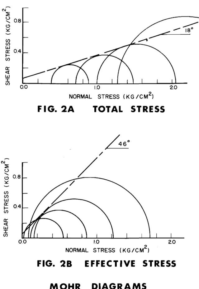
Mohr circles, in terms of total stres ses, are shown in
Figure 2A. Maximum deviator stresses were taken as the failure criterion.
An approximate envelope drawn for these circles indicates a cohesion intercept of O. 05 kg. / cm2 and an angle of s hearing resistance of 180 •
Figure 2B shows the results of the tests in terms of
effective stresses; the approximate envelope indicates a cohesion intercept of
0.05 kg. /cm. 2 and an angle of shearing resistance of 460 •
The high angle of shearing resistance appears to indicate a
strong material. Due to the high pore pressures induced,
s
has a very s mal lma gni tud e and, therefore, the mobilized strength is small. In the case of
complete drainage, a relatively high strength is obtained and succes si ve
deformations result due to the great volume of water that is expelled. These
results are further substantiated by the vector curve plots.
The stress history and behaviour of the sample as it is loaded and brought to failure can indicate the structural properties of the soil. Graphs can be constructed by plotting the history of shear stresses and normal stresses on the incipient failure plane from the beginning of the test to failure.
A vector curve is a plot of shear stress versus effective normal stress on the incipient failure surface; the vector curve is shown
in Figure 3. The behaviour of the peat under load indicates that the pore
water pressures generated by the shear stresses have the consequence of reducing the effective normal stresses on the failure surface; the sample fails at a low strength due to the pore water pressures generated within it.
It can be seen that the cu r v e s for the shear strength tests consistently go towards the left, the origin of the graph; similar curves for drained
material would go upwards to the right.
When strain contours are superimposed on the vector
curves, these can be utilized to predict the approximate magnitude of
strains to be expected during loading. This feature is especially useful
with peat as it serves for both the drained and the undrained cases. It was shown that peat has a stable structure over long ranges of strains induced by static loadings which suggests the necessity of including
undrained movements as a design criterion even in short-term (undrained) loading conditions.
Influence of Cyclic Loading
Pore water pressures generated by shear stresses can be very significant to failure in the case of cyclic loading (Glynn, Kirwan
and Wilson, 1968). Structural breakdown of the fibres and cell walls takes
place as the strain increases with each load application. During the cyclic
loading, major inelastic deformations occur and the peat rapidly deteriorates. For this type of loading, there is a transition point, or
"thres hold stress", where major inelastic deformations begin to occur with associated effects on pore water pressures and resilient modulus. Under low stresses, the resilient modulus is essentially constant (Figure 4)
and the soil is capable of withstanding 1,000 stes s applications. At slightly
higher stresses, the modulus decreased rapidly after approximately 50 applications; at this stage, there is a corresponding marked increase in
pore water pressure. It was hypothesized that the rapid increase in pore
water pressure, as the permanent deformation effects become more
significant, is due to the breakdown of the fibres and c e l l s within the peat
which releases trapped water into the void spaces. It has the consequence
of producing rapid permanent deformations as the effective stresses are reduced and the peat behaves as if there was a sudden increase in water content.
The permanent deformation is not very pronounced until the threshold stress has been approached and, consequently, the peat can
withstand many stress applications. This behaviour has been noted in
the field (Hanrahan, 1964) where it was reported that a roadway embankment was satisfactory until it was used for heavy traffic.
Microscopic Analysis
To examine the effect of s hearing on the structure of peat
13
-along desired planes and examined under a microscope capable of utilizing
reflected light. This approac h was dis carded, however, because of
technical difficulties; the surface of peat, being irregular and dark-coloured,
absorbed the light. An electron microscope has too great a magnification
for this purpose. It was, therefore, decided to conduct examinations using
thin sections and transmitted light. Section Preparations
First, a freezing technique was tried. The sample was
fro zen and thin sections were cut using a microtome. Sections, however,
crumbled and did not retain their original arrangement. Gelatin embedding
accompanied by quick freezing was also discarded for similar reasons. A method originally used by Eydt (1956 and 1962) was modified for the
purpose. Peat cubes were infiltrated with paraffin wax from which thin
sections Were obtained. These were mounted on glass slides and examined
under transmitted light (Ozden, 1967). Microscopic Examination
The pore water pressures generated during the shear of the peat do not allow the peat to mobilize a high shearing resistance.
The term "fibrous interlock" has been used to describe the internal shearing
resistance. In the case of complete drainage, a high shearing resistance
could be obtained provided the large deformations associated with volume changes could be tolerated.
Under application of stress, the individual fibres and particles experience changes in structure and orientation; Figure 5
diagrammatically illustrates the behaviour of two fibres. Pro gressi vel y,
the fibres are forced closer together reducing the void space; as the contact between the fibres increases, the cell structure of the fibres
changes. Figure 6 shows some typical microscopic sections examined
during the research.
The water in the peat can be generalized into four categories:
The first category is the loosely held water in the voids enclosed by what can be considered as the solid constituents of peat.
The second category is water within voids in the solids. For example, water within the void portions of roots, hollow stems, etc. This water is more firmly held than the water in the voids in between the solid constituents.
The third catego ry is the water that constitutes the
rna te ria l itself. The constituents of peat, being of biological origin,
are co rnpo s e d rnai nly of water. Water, therefore, fo r ms an integral
part of what is considered to be the solid constituents. This water,
held in the cells, for instance, can be expelled under certain ranges ofJ
stress.
The fourth category of water is the colloidal water.
It could be expected that the constituent rna te r ial s which
fo r rn the peat would change under stress. It was expected that the slope
of the envelope would not be a straight line as different constituents of
the peat yield and deteriorate. Consequently, the selection of an angle
of s hearing resistance and a cohesion intercept rnay be rather arbitrary..
The rni c r-o s co pi c exarninati.on showed the amo r phous
granular rnate ria'l to be the rno st co mmo nl y encountered ele me nt that
fo r me d the structure of this peat. These generally ranged fro rn 0.1 to 5
mic ro ns . Therefore, a high colloidal activity is probable. A unique
property of colloidal particles is their large surface areas. As, in general,
organic colloids have a high affinity for water, the colloidal pheno me non
rnay be the chief cause of the high water content of peat.
For the peat types examined, the rni c ro s co pi c exarnina tio n
showed a high density as well as a fairly high fibro sity ratio. The fibrous
axes were rno s tly non-woody. These fossilized organs formed an impo r tant
part of the structure of the peat and rnay act as the supporting rne di.a for
the structure.
The rna in body of the cells were identified as being sedges.
The lack of ITlOSS cells was probably due to their being less resistant than
sedge-type cells and not due to their original abs ence. There was a general absence
of leafy tissues which rnay also be due to me chani.c.al breakdown as well as bacterial action.
The cherni cal nature of m Lc ro nodul es is a d ete r mini ng factor in their colloidal activity; the general behaviour of the structure will not be only colloidal as fossilized plant organs d ete r rni ne the fibrous activity. The behaviour of the fibres in turn is partly de te r mi ned by the be haviour
of their cell structure. For instance, the strength of the fibres is influenced
by the amount of water expelled frorn these cells under stresses. In any
case, significant changes in the structure can be expected (both in relation
to colloidal activity and the behaviour of mac rocor gani srns ) as water is
15 -Wa ter Content Relations hips
A unique relationship between water content and
co rrrpr e s s i ve strength exists for the peat tested (Figure 7). For clays, the s a me relations hip has been shown to be repres ented by a single
straight line (Henkel, 1960; Casagrande and Rivard, 1959).
The shape of the curve indicates that less water is expelled fr o rn peat for an increase in strength (after a threshold stress range) than from clayey soils. The rnic ro s c o pi c e xarrii na tio n has shown this to be due to different solid-water phase relationships that govern
the structure of peat under stresses than those for rnirier al soils. Water
fo r ms an integral part of even what is no r rna l l y considered to be the
solid constituents due to their biological 0 rigin. As water is expelled
under stres s e s , solid constituents of peat undergo changes. In other
words, the original rn a te r i a l does not r ernai n the s arn e . This is why the Mo hr -Co ulo rnb strength criterion, so successfully applied to rni n e r al soils, which aSSUITles a straight line relationship (envelope) for the
aarne rna te r ial can only be applied to peat with the reservation that it is only an a pp r oxi rna tio n to a curved envelope.
Conclusions
The rni c r o s co pi c exarrrina tio n has shown that various
categories of water are held in different ways within the peat. The water
content is the controlling factor 0 ver the s hear strength of peat. As so l.id> . water relationships for peat are different f ro rn those for mineral soils,
a straight line strength envelope is only an a.ppr oxi rna tio n to the true envelope. The shear strength tests, with both static loading and cyclic loading, have shown that the pore water pressures generated during shear d efo r rriatio n s have a significant influence on the u l tirriat e failure conditions for the peat.
It has been shown that the peat can corrrpe ten tly support loads under static
loading pro vided the thres hold stres s has not been exceeded under dynamic
loading. In other wo rds, the structure is the controlling facto r ,
AcknowledgITlents
This research work was conducted by the senior author, under the direction of the junior author, as part of the graduate prograITl
in the Faculty of Engineering at McMas ter Uni vers ity. The as sistance
and en cou ra gernent of Dr. N. W. Radforth are sincerely appreciated. The
research was supported by the National Research Council of Canada and the Defence Research Board of Canada.
REFERENCES
Adams, J.1. Laboratory Compression Tests on Peat. Proceedings
Seventh Muskeg Research Conference, National Research Council (Canada), Associate Committee on Soil and Snow Mechanics, Technical Memo randum No. 71, pp. 36 - 54, 1961. Eydt, H. R. N. An Introduction to the Study of the Structure of Muskeg.
Unpublished. M. Sc. Thesis, McMaster University, 1956.
An Assessment of the Component Tissues of Peat in their
-In Situ Arrangement. Unpublished. Ph. D. Thesis, McMaster
University, 1962.
Glynn, T. E., R. W. Kirwan and N. E. Wilson. Measurements of the Dynamic
Response of Peat Subjected to Repeated Loading. Proceedings
of the Third International Peat Congress, Canada, 1968.
Hanrahan, E. T. An Investigation of some Properties of Peat. Geo te chni que ,
Volume IV, p. 108, 1954.
Krzywicki, H. R. and N E. Wilson. Viscosity Measurements to Determine
the Shear Strength of Peat. Proceedings of the 10th Muskeg
Research Conference, National Research Council (Canada), Associate Committee on Soil and Snow Mechanics, 1964.
MacFarlane, 1.C. Guide to a Field Description of Muskeg. National
Research Council (Canada), Associate Committee on Soil and Snow Mechanics, Technical Memorandum No. 44, 1958.
and N. W. Radfo r th, A Study of the Physical Behaviour
---
of Peat Derivatives under Compression - A Progress Report ..Proceedings of the Tenth Muskeg Research Conference, N. R. C, Ottawa, 1964.
Ozden, Z. S. An Investigation on the Shear Strength Characteristics of
Peat. Thesis submitted to the Faculty of Graduate Studies for the Degree Master of Engineering, McMaster University, 1967.
Radforth, N. W. Suggested Classification of Muskeg for Engineering. The
17
-Radforth, N. W. and N. R. N. Eydt. Botanical Derivatives Contributing
to the Structure of Major Peat Types. Canadian Journal
of Botany, 36, 1958.
v Schroeder, J. and N. E. Wilson. The Analysis of Secondary Consolidation
of Peat. Proceedings of the Eighth Muskeg Research
Conference, National Research Council (Canada), Associate Committee on Soil and Snow Mechanics, Technical Memorandum No. 74, 1962.
Stewart, J. M. Cuticle in 0 rganic Terrain as Applied to Copetown Bog.
Unpublished. M. Sc , Thesis, McMaster University,
Hamilton, 196O.
Thaler, G. R. Assessment of the Components of Mineral Peat in their
In Situ Positions Utilizing Thin Sections. Unpublis hed.
M. Sc , Thesis, McMaster University, Hamilton, 1964.
*
-Dis cus sion R. Dubas:
Discuss the sampling techniques, size of sample, and the possibility as well as the effect of sample disturbance on the test results.
AuthorsI Reply:
Field samples were taken at a depth of 2-3 feet by driving
sharpened 4" diameter cutting tubes into the ground. Triaxial samples
were then obtained by driving 1.5" diameter thin-walled tubes into the
field tubes. An examination of the interior of the samples by freezing
and cutting showed that the disturbance was small. (Ozden, 1967).
P. Yurkiw:
*
-Was the cyclic loading used a function of time - that is regular time intervals - or was the pore pressure allowed to return to a constant once load was released before load reapplication?
AuthorsI Reply:
Cyclic loading was a function of time - 10 stress applications per minute and a pulse duration of 0.6 seconds; details
are shown in Figure 3 of Glynn, Kirwan, and Wilson, 1968. During
the cyclic loading, the pore pressures returned to a steady value between
stress applications.
*
-F. A. Gervais:
(i) You mentioned critical nature of threshold stress. Have you in fact done any field work - such as instrumentation - to verify your conclusions?
(ii) What type of pore water pressure device was used -"Springed" Mercury Pot?
Authors' Reply:
(i) We have not performed specific field tests related
to the concept of threshold stress. Other research work, however,
substantiates the concept (Hanrahan, 1964; Wilson and Krzywicki, 1965; Raymond, 1968).
(ii) Pore water pressures were measured by transducer.
*
-J. Hosang:
(i ) In the discussion of repeated loading on the peat
specimens, the re was shown to be a very significant difference in
behaviour of the peat under a loading difference of onl yIp. s ,1. How
important would specimen variation be in explaining the difference in behaviour?
(ii) Could fatigue have contributed to the behaviour variation?
AuthorsI Reply:
Sample variation can be significant for peat and, for this reason, the same sample was used for the test at both stress levels.
19
-The peat sample was initially subjected to 1, 000 stress applications
of a deviator stress of 5.
a
lb. /sq. in., and then the deviator stresswas increased to 6 -0 lb. /sq. in. ; failure o c cu r r ed after 80 stress
applications. As the pore pressure generated by the lower stress level
had stabilized after 120 applications, it is unlikely that the cyclic loading history caused failure under the higher stress level; failure of the sample is very definite and could be attributed to fatigue or breakdown of the fibrous interlock (Glynn, Kirwan and Wilson, 1968).
-N
o
20.0
1.0 1.3 (KG/CM 2 ) 15.0 W Q:o
Cl. セ U ... 1.0 C) :ll:::-
W Q: :J C/) C/) W oNセ Q: o, '"" PORE PRESSURE 10.0AXIAL
STRAIN
(°/0)
DEVIATOR STRESS ... C\I セo
...
0.6
(!) セ-
CJ) CJ)w
a:::
I-CJ)FIGURE
1
N セ U <, 0.8 <.!) セ
-
U) U)w
a::
0.4 セ U)cr
«
w
I U)21
1.0
2.0
NORMAL
STRESS (KG /CM
2)
FIG.2A
TOTAL
STRESS
N セ U ... <.!) 0.8 セ
-U) U)w
a::
I--U)a::
«
w
I U)b
/
L
1.0
2.0
NORMAL STRESS (KG/CM
2)
FIG. 28
EFFECTIVE STRESS
I«t'o
05
ID
EFFECTIVE NORMAL STRESSES (K G /CM
2
)
0.0
セo
... (!) セ-en
w
en
0.4
en
w
I
/
=>
<,
セ
N 0:: NI-en
0:: <tw
0.2
Ien
I
/<,
<,
2.5«t'o
/--FIGURE 3
VECTOR
CURVES
23
STRESS 10 APPLICATJON S 100 1000 I U Z t-Z PᄋTMMセ W Z セ セ 0:: セ 0 · 5 ---セM ---r-0-1 0-2 MセMM 0·3-セMvセ=
5-0 P.5.1. - - - ' カNMvセ=
6·0 P.5.1. -Tセ _ _ - セ 3'0 MMMMセz·o -
--I Mセ---r--"
". : 1-4 P.S.I. WATER CONliNl: 450·'. FINE FIBIItOUS PEAT100 -
-i
l
, セセ セセM セNセ--
-
MエMセ セ MMセMセセMMMセセ セ セセMNセMMKM i-.i- -
Mセ
-
MセM・・M
__
セ
- _ _
セ セセ
.
i PMMセ (!J"I
!
120-140 - セ -- セFIG. 4
STRUCTURAL
BREAKDOWN
•
e
...
....
-
...,
-....
-e
セ-e
セ C>-e
-ja
J...
I
セ
;::
CJ
C(
a
Ik
セ
:z
--..,
C(
at
セ
...
"
セ
at
....
'"
25
600
;
... 500 セ...
z o u•
5
400L セ [...l_-,-c,
&2 G-4 fl'6 "Bセ
HI 2'0 (6.-6.)"'.lIc. (KG,I'C.Q27
-THE VANE TEST IN ORGANIC SOILS R. P. Northwood and D. A. Sangrey
Abstract
In situ vane tests were carried out in a nurnbe r of different rnu s ke g deposits to exarnirie the rne c ha ni s rn of failure and
the effect of variation in vane size and speed of testing. The failure
rrie chanis rn in peat was found to be s irni la r to that in soft clays. The apparent shear strength varied with vane size but was independent of
testing speed. There was an o pti rnurn vane size of 10 CITl d iame te r .
Block s ampl e s were obtained fr o rn one site for laboratory vane tests to investigate anisotropy in the strength of the
peat. In situ tests for anisotropy using vanes of varying shape co nfi rrne d
the laboratory results, and showed that strengths on the vertical plane could be 100 per cent higher than those on the horizontal plane.
- ':::
-TESTS AU SCISSOMETRE VANE, DANS DES SOLS ORGANIQUE
ResuITle
R. P. Northwood et D. A. Sangrey
Des essais in situ au s cis sorriet r e vane ont ete effe c tue s dans plusieurs de pot s de rno s k eg d iffe r errts afin drexarrrin e r I a rne cani s rne
de rupture et lteff et produit par des variations de la grandeur de la vane
et la vitesse des e a s ais , Le rne c ani s me de rupture de la tourbe s 'est revele entre s ernbl.abl e
a
celui des argiles rno l l e s , La force de cisaille-rne nt apparute varie avec l a grandeur de vane rnai s est ind e penda nte dela vitesse dtes s ai , La dirrie ns io n o ptimum de la vane est 10 CITl de d iarn et r e .
Les blocs echantillons ont ete 0 btenu d 'un endroit pour
des e s s at s en laboratoire, afi n de d e te rrriine r anisotropie dans la force
de la to u r be , Les es sais in situ pour 1 'anisotrophie en utilisant des vanes
de diff e r ente s dIrnerisio ns ont co nfi r me Les r e s ultats de laboratoire, et
ont rrio rrt r e que les forces de Le plan vertical pouvait セエイ・ plus de 100
pour-cent superieur
a
celles dans l e plan horizontal.-Introd uction
The field vane test is us ed extensi vel y for the determi-nation of the s hear strength of peat in highway and railroad construction.
It is a simple and relatively inexpensive test which generally gives
satisfacto ry results. There are, however, some factors peculiar to
organic soils which make the test results more difficult to interpret
in these soils than in soft inorganic clays. These factors have been
raised in various publications and are the subject of study in this paper. In an investigation into pavement performance over muskeg in Northern Ontario, MacFarlane and Rutka (1962) showed that in some peat deposits the apparent shear strength measured with
the vane varies with vane size. They used standard vanes, with vane
height equal to twice the vane diameter, and found that in several different deposits the apparent shear strength increased as the vane size decreased.
Helenelund (1967) carried out tests in a very fibrous
peat, also using standard-shaped vanes but with varying numbers of
blades. He showed that there was an unusual failure mechanism in
this type of peat; there being no well-defined failure surface. The
peat tended to squeeze out between the vane blades during the tests and to rebound on further rotation, giving more than one peak strength value.
Finally, there is evidence that some peats show anisotropic strength behaviour (MacFarlane, 1961) and this may also affect the apparent strengths measured with standard vanes.
Muskeg Deposits and Apparatus
In order to obtain more detailed information on the above factors, a program of vane tests was carried out in three areas of muskeg
terrain in Southeastern Ontario during the sum.m.er of 1968. The organic
soils were of varying types, and details of their properties and classifi-cations are given in Table 1.
At Sydenham the soil at one metre depth was a mossy peat strongly reinforced by larger fibres derived from roots and the remains
of large woody plants and bus hes. Below the peat, at 3 metres depth,
was an organic marl with no significant reinforcing fibres. At Mer Bleue
the peat was similar to Sydenham with a mossy matrix but with much weaker reinforcing fibres, derived from the remains of small plants. The peat at Lyndhurst was woody and consisted of branches, twigs and roots from large trees in a matrix of partially decomposed leaves and small plants.
29
-The "Jonell and Nilsson" Swedish vane apparatus used
in the investigation is illustrated in Figure 1. The apparatus consists
of a heavy duty portabl e bo ring rig with a sys tem of hand cranking fo r
inserting and withdrawing the vane. Torque is applied to the rods by
hand through a variable geared loading device in the vane head, which also contains pressure sensitive recording paper on which a record
of torque and rotation are inscribed during the test. The vane is
attached to the rods by a slip coupling which allows rotation of the
rods through 15 degrees before torque is applied to the vane. By this
rne an s the torque due to rod friction in each test is recorded, and may be substracted fro m the peak torque rn ea s u r e d .
A series of vanes of standard shape with four blades was built for tests to investigate the effect of variation in vane size. Vane d Iarne te r s were 5 CITl., 6.5 CITl., 8 CITl., 10. 5 CITl., and 13 CITl.
A 45-degree vane of the type used by Aas (1967) for anisotropy tests
in clay was also built. All the vanes were made of very high tensile
steel and had low area ratios for rni ni murn soil disturbance during insertion.
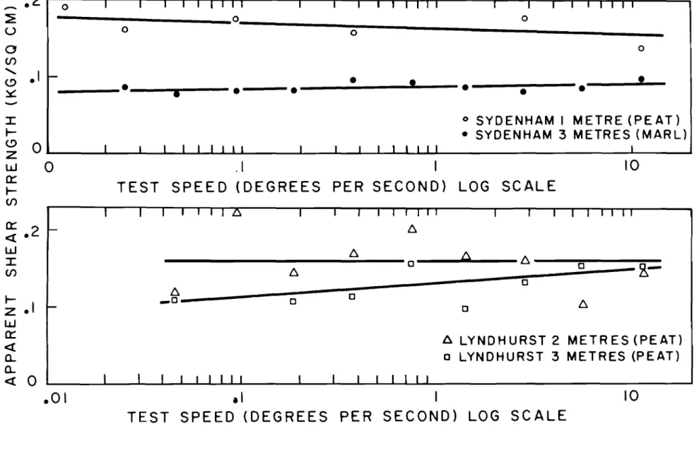
Testing Procedures
P'r e limi na r v tests were carried out at Svderiham and Lyndhurst to d e te r rrii ne a suitable testing speed for tests in peat. The ti rne to failure in a series of tests was varied between a few seconds
and two to three hours. It was found that within the lirnits of accuracy
of the test in peat, there was no noticeable variation in apparent strength
with test speed (Figure 2). Since excess pore water pressures are surely
generated in the failure zone, such behaviour can only indicate co mpl et e drainage, an i.rnpo s sibi.lity for the fastest tests, or else an effective
stress shear strength for peat which is constant in the range of low no r mal
stresses. In this pr'o gr arn a standard test speed of 0.4 degrees/sec. ,
was chosen, since this speed was rno st convenient for use with the
Swedis h apparatus.
At least four tests were carried out with each vane
within a Hrnited area at each site. The tests were repeated at 2 or 3
different depths and the horizontal 'and vertical distance between adjacent
tests was rriai ntain ed at one rne tr e where pes sible. Many of the tests were
extended beyond the peak value of torque up to 360 degrees of rotation,
to d e te rrnine if rno r e than one peak value of torque was obtained. A few
tests were carried out close to the surface at each site so that the rne c ha ni s rn of failure could be ex.arrri.ne d visually.
f'ro m the peak torque with a correction for rod friction. The peat was as s um e d isotropic and a failure surface with a height and diarrie te r equal to that of the vane blades was a s s urn ed .
Effect of Vane Size
Helenelund (1968) considers the strength of undisturbed
peat to be derived both fro rn the fibre strength and fro rn the strength
of the peat rnatr ix . Due to their very low densi ty, the peats tested in
this pr o g r am exist under very low effective stresses. For this reason
the strength derived f ro rn frictional behaviour must be low and the rnain
part of the peat strength rriust be derived fro rn fibre interaction. This
strength, which is independent of no r m a l stress at low effective stresses,
is derived fr o rn interaction between the rnain reinforcing fibres of the
peat, and fr orn s irni la r interaction between the srnal l e r , finer fibres
in the peat rriat r ix, The preliITIinary tests carried out at varying speeds
co nfi r m this strength behaviour. The strength appears to be independent
of the degree of drainage, or pore water pressure, and therefore cannot be of p r edo rrii na.n tl v frictional nature under low effective confining stresses.
The results of individual tests in the peat at Svde nharn
are shown in Figure 3(a). There is a lower lirni.t to the apparent strength
at around 0.11 Kg. /sq. CIn which represents tests where the reinforcing
fibres have the least influence. The peat rria trix strength is probably
close to this strength but slightly below it. The test results are scattered
and the scatter increases with decreasing vane size, since individual reinforcing fibres have rno r e influence on the s ma l.l e r varie s , Any given reinforcing fibre requires the s a rne stress on the failure surface to break
it or pull it out whether the vane is large or srn a.ll , This stress is, however,
large co rnpa r ed with the stress required to shear the rna trix and the reinforcing fibre increases the apparent strength obtained fro In the
srnal le r vane by a greater percentage than that fro rn the larger vane. The
effect is dependent on the spacing of the reinforcing fibres relative to
the vane sizes used. When the vane size used is large enough to ensure
that a representative nurnb e r of reinforcing fibres is sheared in the rna jo ritv of tests, the scatter of results is s mal l and the average is representative of the average strength of the peat.
Figure 3(b) shows the rne an values of the apparent
strength in the peat at Syd e nharn and the statistical standard deviation
f'ro rn the rne an , The 10.5 CIn vane shows a low scatter of results with
a rn ea n strength of 0.15 Kg. /sq. CIn which represents the average
strength of the peat derived fr o rn the fibre and rnat r ix strengths. At
vane sizes below 10.5 CIn the vane is too s ma l l to effectively give a reasonable average strength, and the standard deviation increases
31
-site it was found to be irnpo ssible to insert the 13 CIT1 vane by no r rna l
rne an s , due to the high fibre strength, down to one rne tr e depth. The
single result was obtained by preboring a hole, and represents the strength in a slightly disturbed condition.
The rne an apparent strength values at Sydenharn do
not lie on a SIT100th curve, probably due to variations in peat strength
within the test area, but the general trend of results is sirrii.la.r to
other sites. Figure 3 shows the rne a n apparent strengths at seven
locations in Eastern Ontario. In the organic rna r l at 3 rnet r e s depth
at Syden harn there are no reinforcing fibres, and, consequently, no
variation in measured strength with vane size. At Lyndhurst and
Mer Bleue the results follow the same pattern as those in the peat
at Sydenham. The mean strength remains constant for the larger
vanes but below about 8 to 9 cm diameter the measured strength tends
to increase as the vane size decreases. The percentage increase in
apparent strength with the smaller vanes becomes larger as the mean strength increases, and the mean strength at these sites increases as
the strength of the reinforcing fibres increases. There were no problems
in the use of the 13 cm vane at Lynd hurst and Mer Bl.e ue , and the standard deviation of the results with each vane at these sites decreased as the vane sizes became larger in a roughly linear relationship.
MacFarlane and Rutka (1962) published apparent shear strengths obtained in a muskeg deposit with different sizes of vane. A typical result has been plotted on Figure 4 for comparison purposes.
The results from the two larger vanes are close to the pattern of results at Sydenham but the results from the small vane seem unusually high. MacFarlane and Rutka suggest that their unusual results may be due to
rod friction, dial error or peat structure. Since the increase in apparent
strength with the smallest vane is higher than the increase due to structure in other peats, it seems probable that the high result is due to
under-estimation of the effect of rod friction.
In the three deposits tested, the rrnrnrnurn vane
diameter for consistent results was about 8 or 9 crn.. , but it is possible
that in other types of peat the rnirrirnurn diameter might be higher.
Since a 13 ern. diameter vane is difficult to insert in some types of peat,
the optimum vane size for general use in peat is about 10 ern (or 4 inches
diameter.
Anisotropy in Peat Strength
A 45 -degree vane (Aas, 1967) was manufactured to
in an isotropic soil. Comparison of the results from these two vanes at Lyndhurst showed that the ratio of the apparent strength with the conventional vane to that with the 45-degree vane varied between 1.1
at one metre depth to 1. 3 at three metres depth. Since the conventional
vane measures strength mainly in a vertical plane, whereas the 45-degree vane measures the strength in two directions at right angles, it seemed likely that the peat at Lyndhurst was stronger in the vertical direction than in other directions.
To verify the abo ve results, b10 ck samples were taken
from the peat at one metre depth for laboratory tests. A small laboratory
vane was inserted into the peat in the vertical and horizontal directions
and at 45 degrees to the vertical. The results showed that the strength
measured by the vertical vanes was 45 per cent higher than that measured by the horizontal vanes and that the strength on the inclined plane was
midway between the horizontal and vertical strengths.
If
a ratio ofconventional to 45 -degree vane strength of 1. 1 corresponds to a vertical
to horizontal strength ratio of 1. 45, it may be inferred that the vane
strength ratio of 1.3 at three metres depth corresponds to a strength
in the vertical direction about 100 per cent higher than that in the ho rizonta1
direction. This result is of considerable significance since it was not
readily apparent, from examination of samples taken by a peat sampler, that the peat strength behaviour was likely to be highly anisotropic. Examination of block samples, however, showed that the general trend was for branches and twigs in this peat to lie horizontally, and it seems
probable that this trend also existed in the finer material. In contrast to
the behaviour at Lyndhurst, the field vane tests at Mer B1eue showed that the peat at this site was almost isotropic in its strength behaviour. Hence, it can be seen that anisotropy may lead to problems in the inter-pretation of results from conventional vanes, and that these results should be used with caution especially if no detailed examination of the peat
structure is made. Mechanism of Failure
Visual examination of tests carried out close to the surface at all three sites, with a range of vane sizes, showed that there
was a cylindrical surface at failure in all tests. The highly disturbed
area of the failure surface was about 2 nun. wide. There was no evidence
of any squeezing out of the peat between the vane blades, although some compression occurred at the leading edge of each vane and a slight gap was noticed behind the trailing edge.
The torque -rotation curves for the tests at all sites showed that the torque rose smoothly to a peak at about 40 to 60 degrees
33
-rotation and then dropped slowly. The torque continued to drop
smoothly through as much as 360 degrees rotation with no evidence of secondary peaks, except for occasional tests where the vane hit a
large root or major obstruction. All the peats tested were fibrous
to s o m e extent, and the peats at Mer Bleue and Sydenham had a high
fibre content (F2 on the von Post scale). The tests published by
Helenelund (1967) which showed secondary peak values of torque, were carried out in a peat COITlPO sed almo st entirely of fibres (F 2 - 3 on the von Post scale).
The above results indicate that peats rna y have a high fibre content and still show a no r rnal failure rn e c hanis rn , It appears that the only tests in which an unusual failure rne c hanis rn will occur are those in which almost the entire structure of the peat is
corripo s ed of the larger types of fibres. If an apparatus similar to
the Swedish apparatus is used, the record of torque against rotation gives an irnrnediate indication of any unusual failure rn e c hanis rn and, where this occurs, the results should be treated with caution.
Conclusions
The series of tests described in this paper have yielded further i.nfo r rna tio n on SOITle factors which affect the interpretation of
vane tests in organic soils. The following conclusions have been drawn
from the work:
1. The speed of vane testing in peat has little
effect on the rn ea s u r e d strength because the strength is essentially constant in the range of low effective no r m al stresses.
2. There is an o ptirnum vane size for tests in peat of about 10 CITl d ia me te r by 20 ern high (or 4 inches
by 8 inches). Srnal le r vanes tend to give higher
average strengths due to fibre effects, and larger vanes rriay cause practical difficulties in insertion. 3. Anisotropy in strength behaviour is of considerable
significance in some Canadian peats, and conventionally
shaped vanes rnay not record the average strength of
the peat.
4. Unusual rrie c ha ni s rns of failure in the vane test probably occur only in peats which are co mpo s e d alrno st entirely of larger fibres.
REFERENCES
Aas, G. Vane Tests for Investigation 0 f Anisotropy of Undrained
Shear Strength of Clays. Proceedings of the Geotechnical Conference, 0 slo, Vol. 1, p. 3, 1967.
Helenelund, K. V. Vane Tests and Tension Tests on Fibrous Peat. Proceedings of the Geotec hnical Conference, 0 s l o ,
Vol. 1, p. 199, 1967.
Compres sion Tension and Beam Tests on Fibrous
Peat. Third International Peat Congress, Canada, National
Research Council, 1968.
MacFarlane, 1. C. and A. Rutka. An Evaluation of Pavement Performance
Over Muskeg in Northern Ontario. U.S.A. Highway
Research Board Bulletin 316, p. 32, 1962.
Aspects of Research and Development of Roads Over
Organic Terrain in Japan. Canada, National Research
Council, Associate Committee on Soil and Snow Mechanics, Tech. Memo. No. 71, p. 149, 1961.
*
-Dis cus sion G. Hollingshead:
(1) You mentioned three peats, two of which were fibrous
and one amorphous. Which of these were tested for anisotropy with
the lab vane?
(2) Would the small size of the lab vane be a significant factor with regard to your conclusion concerning anisotropic strength? Authors' Reply:
(1) The laboratory vane tests described were carried
out on the peat from Lyndhurst. Due to the small size of the laboratory
vane, it cannot be used in many fibrous peats. The fibres in the peat
matrix at Lyndhurst, however, were generally short in relation to the
vane size. Furthermore, the laboratory tests were used only to confirm
35
-(2) No absolute values of strength were measured using the laboratory vane and the results were used only to compare strengths in different di r ec tioris ,
-
)';:-F.A. Gervais:
(1) What is the ratio of vertical to horizontal vane shear strength?
(2) Do you use this average value along the slip circle when designing?
Authors' Reply:
(1) The ratio of vertical to horizontal shear strength is discussed in the section on anisotropy.
(2) An average value of shear strength should be acceptable
for most design purposes but this will depend to some extent on the shape
of the likely failure surface. The average strength of the peat may be
obtained by the use of a 45-degree or similarly shaped vane, or by
calculation from the results from two vanes of different height to diameter ratios.
-Table 1
Sydenham
Radforth Classification BDF
von Post Classification セ B3F
2 R2VI
Density 1. 1 gm/cu. em
Average Moisture Content 700%
Mineral and As h Content 150/0
Lyndhurst Mer Bleue
AF EI
H 3_s"B3 F l R IV 3 H3B3F2R2Vl
1.1 gm/cu. em 1.1 gm/cu. em
600% 800%
37
o
•
o•
o
•
-
-
.
•
o
- - - - o セMMMMM⦅i ·
2
I
(0;----'1---'---
I I
セ]セセ]Z[Z]]MGMtLMョョMMGMtGBBBBGBM
Ua
II
I I I I I I I (f) 11111 <,<9.1
I I I I I I I I Iセ
I
-o
SYDENHAM I METRE (PEAT)
• SYDENHAM 3 METRES (MARL)
.1
I
10
TEST SPEED (DEGREES PER SECOND) LOG SCALE
:s
I
1I
I I I セI
e,..l セA
co 0 セ 0 B.-セ 0 セ 0 _ 0 0 セ 06.
LYNDHURST 2 METRES (PEAT)
o
LYNDHURST 3 METRES (PEAT)
,
,
, I I , ,.1
I
10
TEST SPEED (DEGREES PER SECOND) LOG SCALE
セ