Publisher’s version / Version de l'éditeur:
Technical Note (National Research Council of Canada. Division of Building Research), 1972-08-01
READ THESE TERMS AND CONDITIONS CAREFULLY BEFORE USING THIS WEBSITE. https://nrc-publications.canada.ca/eng/copyright
Vous avez des questions? Nous pouvons vous aider. Pour communiquer directement avec un auteur, consultez la première page de la revue dans laquelle son article a été publié afin de trouver ses coordonnées. Si vous n’arrivez pas à les repérer, communiquez avec nous à [email protected].
Questions? Contact the NRC Publications Archive team at
[email protected]. If you wish to email the authors directly, please see the first page of the publication for their contact information.
NRC Publications Archive
Archives des publications du CNRC
For the publisher’s version, please access the DOI link below./ Pour consulter la version de l’éditeur, utilisez le lien DOI ci-dessous.
https://doi.org/10.4224/20338502
Access and use of this website and the material on it are subject to the Terms and Conditions set forth at
House Foundations in Swelling and Shrinking Soils
Hamilton, J. J.
https://publications-cnrc.canada.ca/fra/droits
L’accès à ce site Web et l’utilisation de son contenu sont assujettis aux conditions présentées dans le site
LISEZ CES CONDITIONS ATTENTIVEMENT AVANT D’UTILISER CE SITE WEB.
NRC Publications Record / Notice d'Archives des publications de CNRC:
https://nrc-publications.canada.ca/eng/view/object/?id=33755079-d17b-4284-9f60-7f5999793625 https://publications-cnrc.canada.ca/fra/voir/objet/?id=33755079-d17b-4284-9f60-7f5999793625
DIVISION OF BUILDING RESEARCH
NATIONAL RESEARCH COUNCIL OF CANADA
••
'Jr
EClHI N J[CAIL
NOTE
No.
566
PREPARED BY J. J. Haznilton CHECKED BY C. B. C. APPROVED BY N.B.H.
DATE August 1972
PREPARED FOR General Distribution
SUBJECT HOUSE FOUNDATIONS IN SWELLING AND SHRINKING SOILS
As one of its continuing research prograllls, the Prairie Regional Station of the Division of Building Research, National Research Council of Canada, has carried out extensive studies of the performance of various foundation designs in the troublesome swelling and shrinking soil conditions found in Regina, Winnipeg, and numerous smaller
urban centres throughout the Prairie Provinces. The objective of
these studies has been to aid in the development of improved
founda-tion design and construcfounda-tion practices. Efforts have been made to
provide the basic information necessary for designers and builders to develop practical, economical solutions to problems that now result in many millions of dollars of increased maintenance costs and reduced service life costs for houses and other types of
build-ings, municipal services and transp'Jrtation facilities. Several
research and engineering papers have been prepared and presented before the design professions, and many lectures and workshops have been conducted for the construction industry throughout the
Prairies. The main technical factors have been clearly identified.
Designers now have a large number of workable alternatives from which to choose depending on economics and other non-technical considerations.
The Division of Building Research has been closely involved in the technical and economic research conducted on the earlier
COpy
.
: '.' LNセ (.. '''''''"r
.,1 ャセNセᄋG '. ,'",,"l:J. . 1,'J. ( ; " ' . 'r:i ;' C:.
,,<; .t
. セ.
NOT TO BE
REMOVED
FrtOM ROOM
201
D
'
'In,
GセLd.r.·, GセGェZB • '" ...セNAャ
ft'''''''
"
, . ..'t
n
,.,.J }.:
:
. '...'.
セQᄋセ':!
-2-research houses built in the HUDAC (NHBA) Mark Series. In
the case of the Mark IX the Prairie Regional Station in Saskatoon was pleased to work with various research committees, designers and suppliers, and to be able to conduct the following research program designed to assess carefully the performance of the steel basement.
Basement Walls, Floors and Foundations Design
There are basically two approaches to designing foundations for swelling and shrinking soil conditions as encountered in Regina. For the majority of small buildings it has been traditional practice
to found these on relatively shallow spread footings. A designer,
recognizing that such footings within the "active" zone of ground movements undergo considerable movement, will usually try to include sufficient structural strength to minimize damaging
differen-tial movements within the structure, e. g. セ he will require concrete
walls to be reinforced with steel or will provide an adjustment system to correct for movements of the foundation units so that these movements are not transmitted to the main structure above, e. g., adjustable length columns commonly called tlteleposts".
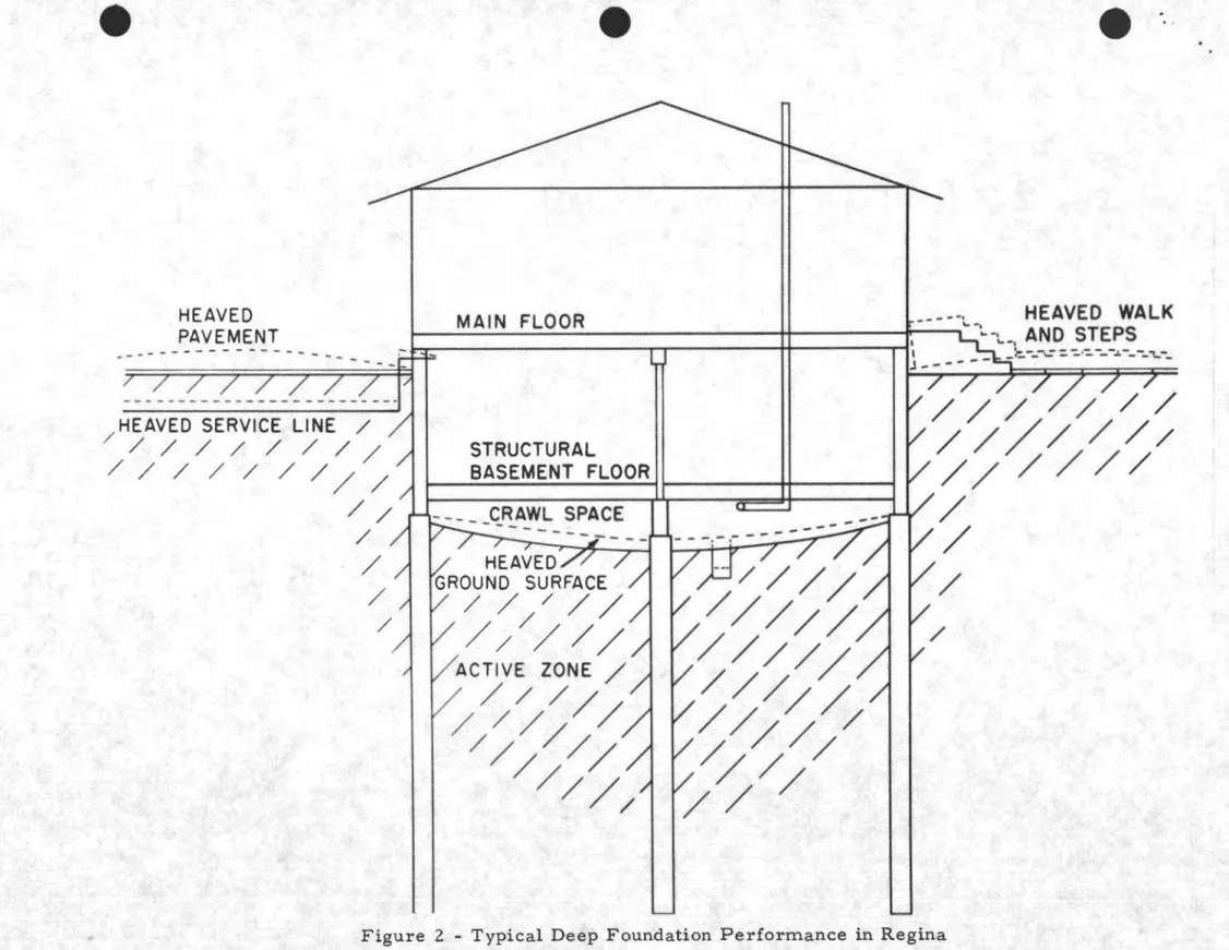
The second design approach, commonly adopted for larger commercial, institutional and residential buildings, is to utilize deeper foundations that undergo little or no movement because they gain their bearing capacity in more stable ground conditions below
the tlactive" zone. Trouble-free foundations of this type require
strict attention to certain design and construction details, including: sufficient tensile strength to resist uplift forces; void spaces
maintained between the soil and the grade beams, pile caps, footings and structural floor systems to insure against heaving; and special attention to connections or transitions between the main structure and all ground supported appendages, such as door steps. sidewalks, driveways, planters and water, sewer, gas, power and communica-tion conduits.
Typical vertical movements for the two main types of
founda-tions in Regina are illustrated in Figures 1 and 2. The "active"
zone, as shown in both cases, is much deeper around and below buildings than in undeveloped prairie conditions because of:
1. The unloading of the subsoil, caused by the removal of soil
·
.
-3-than the combined weight of the house and basement;
2. Irrigation, roof run-off, snow melt and possible leaks
from service pipes increasing the amount of moisture around building s; and
3. Changes in ground surface condi.tions, such as pavements
and new types of vegetation, that significantly alter the run-off infiltration-evaporation balance.
For the conventional spread-footing foundation shown in Figure 1, the perimeter footings, interior footings and floor slab
all heave at varying rates. Perimeter footings often heave at a
rate of 1/3 to 1/2 in. per year for many years after construction, interior footings may rise at a rate of 1/2 to 3/4 in. per year and
basement floor slabs have been known to heave 1 -1/2 to 2 in. in
a year. If nonuniform soil moisture conditions persist around a
building, a general tilt or severe cracking of the walls may
develop. Careful adjustment of the screw jacks on basement
columns can do much to keep the main floor reasonably planar (if not level) and can greatly reduce superstructure damage. The ground surface around the house may undergo varying
amounts of seasonal and long-term heaving dependi.ng on the
land-scaping and irrigation practices of the homeowner. Surface heaving
of lawns can often exceed eight in. in a few years.
For deeper foundations, as shown in Figure 2, the perimeter
and interior foundation units heave little or not at all. The unloading
effect due to excavation is just as great as for a spread-footing foundation so there is the same tendency for the ground surface in crawl spaces to heave an inch or more per year if moisture
becomes available. The ground surface around the building
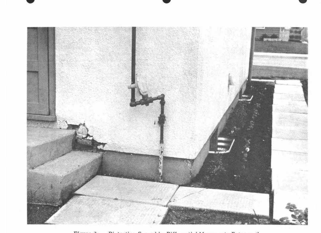
under-goes similar seasonal and long-term heaving effects as in the first case, but are usually accentuated because the ground movements are more sharpIy contrasted against the non-moving buildings. SOlne of these effects can be seen in the photo insert in Figure 2.
Measurements of Vertical Movements of Foundations for the Mark IX House
Over the past 20 or more years, the Division has found that reliable measurements on bUilding found3.tions can be made
•
-4-with a precise engineer's level if the measurements are referenced
to reliable deep bench marks. Using two bench marks installed on
the Mark IX lot and a Wild
Nm
Metric level, vertical elevationchanges are being measured to O. 1 mm (0.004 in.); the
over-all accuracy of the survey is well within ± 2 rnrn (0.08 in.).
By surveying to this accuracy. even minor variations and trends can be detected that may be helpful in making predictions and assessing factors of secondary importance.
The results of these vertical movement measurements will be of basic value in assessing the performance of the foundation
and superstructure. These results will be compared with those
obtained during the past 12 years from many other foundations in Regina.
House Basement Walls as Earth Retaining Structures
In addition to transmitting the load of the building above to the foundation units below, perimeter basement walls must also resist the horizontal forces exerted by the earth backfilled around
the basement. In most soils the deeper the basement below ground
surface the higher will be the lateral earth pressures exerted on
the basement walls. The design of walls to retain sandy or gravelly
soils is a relatively straightforward engineering problem. For
swelling clay soils, like those in Regina, the horizontal pressures exerted on retaining walls can range from no p:o:essure where the clay remains standing unsupported in a new excavation or where drying shrinkage has opened a crack which separates the soil from the wall, to pressures of several tons per square foot when dry clay, densely compacted against a rigid wall, absorbs moisture. Because measurements of actual earth pressures developed by clay backfills are very expensive and complicated to obtain designers have little factual information from which to select
design figures. It is not uncommon or overly conservative at
this time to assume that the lateral earth forces exerted by a swelling clay against a rigid basement wall may be twice those exerted by a granular backfill soil.
In addition to the normal horizontal earth pressures, heavy loads on the ground surface near a retaining wall will greatly
-5-increase the pressures that the wall must resist. For example,
a heavy bulldozer or truck driven close to a foundation wall can more than double the horizontal pressures against that wall.
The relative rigidity of retaining walls affects the magnitude of pressures that soils develop; the more rigid the wall, the higher
the potential pressure. A flexible wall, in yielding away from the
soil, can substantially reduce the pressure exerted against it.
In addition to the requirement of safety against sudden or
progres-sive collapse of a retaining wall, practical liInits must be set on the amount of deflection to be permitted.
Measurements of Horizontal Movements of and Earth Pressures Against Basement Walls of the Mark IX House
There is a dearth of information needed for the most
eCOl'lOmical design of basement walls in swelling clay soils. The
varying degrees of rigidity offered at mid-spans and at the framing supports of the steel basement provide an excellent opportunity to measure pressures exerted by clay backfill.
Two types of earth pressure cells have been installed -=1t
three locations on the outside o"! the basement walls. Both types
of cell translate the earth pressure into hydraulic pressure which
can be measured to an accuracy of better than
-t
10 per cent(t
O. 5 Ib/sq in. ).Because the pressures developed against the wall are greatly affected by the rigidity of the wall, it is necessary to
measure the horizontal deflections of the wall siInultaneously. They
are measured at each earth pressure cell and at 41 additional points.
The measurements are made with a tape extensometer relative to two reference bench marks installed below the basement of the
house. Over-all accuracy of measurement is approxiInately 2 rnm
(0.08 in.).
These measurements will provide fund:unental informatio:l to structural designers and found=1tion engineers and should be of value not only in assessing this particular foundation design but in refining other foundation designs.
-b-Thennal Perfonnance of Foundation Walls
Uninsulated concrete or steel basement walls can account for 1/4 to 1/3 of the total heat loss from prairie houses in winter. Most of this heat los s can be stopped by applying 1-1/2 to 2 in.
ot expanded polystyrene insulation to the outside 01" to the inside
of the basement walls, and by carefully sealing off any air leakage
between the basement wall and the sill plate. There are a number
of technical advantages in applying the insulation to the outside of basement walls; two practical advantages are that the inside o! the basement wall is more easily finished and that it appears neater
even if left unfinished.
Measurements of Thennal Perfonnance of the Basement Walls A number of thermocouples have been installed .:.\t various locations within and on the insulation, au space s and steel
com-ponents of the basement wall. Measurements made with these
thennocoup.les (particularly 、ャセイゥョァ the extremely cold periods
of the year) will provide quantitative infonnation on the thermal resistance of this wall design.
Results of the Research
All the information gathered in these studies will be mad,s available for designers and builders through the usual publication
procedures of the Division of Building Research. Some of these
re suIts may have an almost immediate impact on house building practice; others may take longer.
There is a considerable potential saving ヲッセ the house
owner in an improved foundation system that will reduce maintenance
and operating costs and extend the useful life of the house. SOlne of
these innovations may have slightly higher initial costs than current
conventional construction. If incorporated in optimum designs,
however. these improvements will lead to low maintenance costs and maximum utilization of floor space.
e
e
e
"
....7
/ / / / / / / / / / / / / / /- - -
- -HEAVED LAWN--/1-. - - - -
r i l l
I
⦅セ I HEAVED WALK AND STEP FLAT IF TELEPOST ,-. ADJUSTED CORRECTLY... ---.J-
_
"'w.' ,... J ZZZNLセMZNNセM[ MZNNセ セ ZエNセM⦅ByBG⦅MNZZ⦅ / / / / / / / / / / / / / / / / //
/ / / / / / / / / / / / / / / / / / / / / / / / / / / / / / / / / /heaセセd⦅
セlNYPr
_ _ _ / / / / / / / / / / / / / /---
-
-
- -
-
セMMMM---
-
-
-
-
--
/ / / // /
ゥセ
--.--
-i
r --..-i
I- --==:j / /
/ / / / / / / / / / //
/ / //
/
//
/
/ 2.3':'; / / / / / / / / / / / // / / / / / /
/ / //
/ / / / / //
/ //
/ //
/
/ /
/ / // /
/ // /
/ / / / //
/
/
/ / / 7.2':'; /ACTIVE ZONE / / / / / / // /
/ / //
/ /
/ / // / / / / / / / / / / / / / / /
/ //
/
/
// /
/ //
/ / / // / / / / / /
/ /
/ /
/ // /
/ / / / / / // / / / / / / / / / / /
/ / / / / / / / / / / / / / //
/ / / / / / / / /•
e
•
5.0 4.0 3.0 2.0 1.0o
-1.0 WALL MOVEMENTS I 1 I Ia. Observation point indicating maximum heavino b. Mean chanQe in elevation of all points c. Observation polnt indicatino maximum initial
setttement and subsequent heovlno
1'1
b)
セ Concrete basement
walls
placed Sept. 18.1961
::::::--
セ c.I
MAXIMUM - MINIMUM CHANGES IN FLOOR ELEVATION
r- I L.... T I
-I -I I---I セ a セ...
--l
-
'--/L..-1 /
-...セ セャNNNNNM---
b. , ...-,,--L
-___ '- I-.
__
...
.-.
..-...
-._._-I.---
1---c.
セ_.-
-II
._
-IT-
-.J
I...
セI
I ---l I -I..J
5.0 4.0 3.0f3
:z:
2.0 o セ 10o
-1.0 4.0 3.0 2.0 1.0o
-1.0 SUBSOIL MOVEMENTSGauge measuringIsubsoil vertical movements at a depth of 2.3 feet
-
---r--= ]. _...
..
__....
-_
....
-Excavation
..
----_
...-
...
Sept.11.1961 セ セ•••••_···Oepth of 7.2 feetセM
.---I .---I .---I .---I .---I 1 1 .---I .---I I I I I 1 III I I I I I I l l l l l l l l l 1 I I I I I I l i l i I I I I I I I I I II 1III I I I I 11111111111 ' " 1 1 1 " 1 1 1 I 11 I I I I I I I I I 1 I
1961 1962 1963 1964 1965 1966 1967 1968 1969 1970 1971
•
e
e'"
STRUCTURAL BASEMENT FLOOR II II I HEAVED GROUND SURFACE/
/ / /
/
/
/ /
/
/
/
ACTIVE ZONE/
/ / /
/ /
/
/
//
/
HEAVEDPAVEMENT
Jf:
-
MAIN
FLOORセ
セMMMMMlBBLM⦅
セセセvセセepセalk
セ
'
s|ᄋ⦅セMMᄋMM
-.--; , , ; , , , , - - J - - - -'- - -
-"'---> 5 ) )
>
HEAVED SERVICE LINE /
/ / / / / / / / /
/ / / / / / / / /
/ /
/
/
/
/e
e
e
Figure 2a - Distortion Caused by Differential Movements Between the