READ THESE TERMS AND CONDITIONS CAREFULLY BEFORE USING THIS WEBSITE. https://nrc-publications.canada.ca/eng/copyright
Vous avez des questions? Nous pouvons vous aider. Pour communiquer directement avec un auteur, consultez la première page de la revue dans laquelle son article a été publié afin de trouver ses coordonnées. Si vous n’arrivez pas à les repérer, communiquez avec nous à [email protected].
Questions? Contact the NRC Publications Archive team at
[email protected]. If you wish to email the authors directly, please see the first page of the publication for their contact information.
NRC Publications Archive
Archives des publications du CNRC
This publication could be one of several versions: author’s original, accepted manuscript or the publisher’s version. / La version de cette publication peut être l’une des suivantes : la version prépublication de l’auteur, la version acceptée du manuscrit ou la version de l’éditeur.
Access and use of this website and the material on it are subject to the Terms and Conditions set forth at
Closed-loop controlled tensile strength testing method for multi-year
sea ice
Sinha, N. K.
https://publications-cnrc.canada.ca/fra/droits
L’accès à ce site Web et l’utilisation de son contenu sont assujettis aux conditions présentées dans le site
LISEZ CES CONDITIONS ATTENTIVEMENT AVANT D’UTILISER CE SITE WEB.
NRC Publications Record / Notice d'Archives des publications de CNRC:
https://nrc-publications.canada.ca/eng/view/object/?id=0f438e18-52c0-4bad-9e3c-c3703dbd062e
https://publications-cnrc.canada.ca/fra/voir/objet/?id=0f438e18-52c0-4bad-9e3c-c3703dbd062e
S e r
TH1
N21d
lo.
1 6 o 2 ) $ I
National Research
Conseil national
c .
2
Council Canada
de recherches Canada
-BLDG
,Institute for
lnstitut de
- --
Research in
recherche en
Construction
construction
Closed-Loop
Controlled
Ter;
Testing Method for
Multi-Year Sea Ice
by
N.K. Sinha
Stn
A N A L Y Z E D
Reprinted from
Proceedings, Eighth International Conference on
Offshore Mechanics and Arctic Engineering
The Hague, March 19-23,1989
Volume IV, p. 1 - 6
(IRC Paper No. 1602)
NRC
-
CISTIL I B R A R Y
NRCC 30476
B I B L I O T H E Q U E
On a mis au point une mkthode servant
B
fabriquer un Cchantillon en forme d'os pour
chiens ou d'haltkre dont la section de mesure uniforme, faite de n'importe quelle glace
naturelle, permet d'effectuer sur celle-ci des contrales en traction. Les bouts de
1'Cchantillon sont faits de glace multicouche:
et
la
g e o m 6 ~ e
de
la
coupe
transversale est
compatible avec la structure granulaire de la glace.
La section &
mesure
est
assez grande,
de sorte qu'elle peut contenir un nombre de
grains
suffisant
pour
kviter tout effet
gCom6mque et qu'on peut y monter la jauge
de
deplacement pour effectuer
des
essais h des
vitesses de deformation constantes h l'aide d'un appareiI fonctionnant
en
boucle fem6e.
L'utilisation de la technique est illustree par des
exempIes
de
rc5sultats d'essais auxquels
a
CtC sournise de la glace de mer
B
grains prismatiques,
sous
forme
de
carottes
de
300 mxn de
diamktre, provenant d'un
floe
pluriannuel de
1'Extrbe
Arctique.
L'aureur
dCcrit
aussi des
mCthodes servant h effectuer des analyses mimstructurales apr&s essais.
I
@I
he
American Society
of
Mechanical Engineers
Reprinted From
Eighth International Conference on Offshore
Mechanics and Arctic Engineering-Vol. 1V
Editors: N. K. Sinha, D. S. Sodhi, and J. S. Chung
Book NO. 10285D
-
1989
CLOSED-LOOP CONTROLLED TENSILE STRENGTH TESTING
M E T H O D FOR MULTI-YEAR SEA ICE
Nirmal K. Sinha
Geotechnical Section Institute for Researchin
Construction National Research Council of CanadaOttawa, Ontario, Canada
R m e t h d has been developed for rnaklng a dogbone-
w
dumbetl-shaped speimen with
a
uniform auge seaion made of any natural ice to be tested in tension. $he specimen ends are madeof
built-up ice and the cross-sect~onal geornstrj is cornpatlble with the grain structure of the ice. The gauge section is large enoughto
contain a sufficient number of grains to avoid any geometric effect and to mount the displacement gauge for mnductjng zests under dosed-loop controlled constant strain rates. The application of the technique is Illustratedby
examples of test results on colurnnargrained seaIce
obtained from a rnultl-year floe in the High Arctlc i? the formof
300 rnm diameter cores. The paper also descr~bes methods of carrytng out post-test microsb'uctural analysis.Introduction
TenslFe tests In pdycycrystaltlne metals, alloys
and
ceramb are normally performed using dumbell- or dogbone-shaped specimens. This type of gmme'hy hetps in generating the maxlmum stress andstraln fteld in the gauge section and at the same time maintains the deformation field uniform in this zone. The size of the specimens to be used is usually dictated b the fest facilities available and the machinablily of the material. dnce the grain sYsr are small, it IS often assumed, and rightly so, that there are a large number of
grains across the diameter or the minimum dimension of the gauge section.
The rain sire of natural polycrystalline Ica Is usually several
orders o?rnagnitude larger
than
that of metals, alloys and ceramics.The specimen size for ice should therefore be
huge
compared to that for other materials ifa
sufficient number of grains (more than tengrams,
atsoording to Jones and Chew, 1981) is to be accommodated wrthln the eclmen to avo~dany
geometric effect. Providing an adequate spermemen size for direct ternlie tests on fine-gralned, granular im is not dmicult Hawkes y d Me!lor, 1972; IBurdick,
t
975) but it has been a chron\
c problem In testlng natural ice [Peytan, 1966, Saekl st al, 1978). This is becauseof
thed~fflculty of transpmng large mounts of ice from the f~eld to the laboratory. However, many tests on laboratory grown sallne ice have also been carried out In which this constraint was overlooked or ignored. Thin-section p b t q r a p h s of fractured specimens show only
two
gralns (Fig. 30 In Dykins, 1970) and three grains (Fig.15 In Pykins, 1967 and Fig. 6 in Oyklns, 1969) across the speciyen diameter. All these authors used specimens with reduced-section diameter or wldth in the range of 30 m,m. Moreover, no dlrect measurements ofstrah
in the gauge sectron were carried out. An improved methodfor
tsnsne testlng of ice and frozen soll, using Presented at the Eighth International Confernnee onOffshore Mechanics 8nd Arctic Enginearlng The Hague
-
Msrch 19-23, 1989special end caps and a pair of displacement gauges mounted on the gauge section, was presented by Eckardt (1982). This rocedure was essentially followed by Kuehn et al (1988) who used &thane end-caps described by Lee (1986).
The most significant aspect of the new test technique is the fact that it uses the same specimen geometry as the test specimens used for metals, alloys and other materials. However, the final finished ice specimens are very large (overall length up to 700 mm ,has been used), siqnlicantly different from typical tensile test specimens generally requ~red for other materials.
This technique, originally developed for fresh-water Ice, has been adopted for testing first-year
as
well as multi-year sea Ice.Special treatments of the s eclrnen are required for such
S
pes of ice. It has been rucCessfulL applied in tensile testing of murnnar grained ice from a multi-year floe in the Canadian High Arctic under closed-loo controlied mnstant strain rates. This paper will describe tte technique and givesome
resultsto
show its general applicability.Descri~tion of Available Field Ice
tt Is common practice to obtain Ice
from
the fiekl in the form of blocks or lindncal cores. Ice testing de ends reatly on the avallabllity 2 i c emres
or blocks large enougl to mafe the requlred specimen. Blocks are suitable for obtainingsan~p,~..s
from the top layers of natural ics masses. Since chain saws are used, it is extremely difficuk to reach depths greater than one metre. Accordingly the core method is more cammonly employed. However,!he
core augers readily available have diameters in the range of 76 mm to 100 mm and can, therefore, only provide enough material for spsdmens that aro verticalty oriented w~th respectto
the ice Dover. This, in fact, limited Kuehn et al (1988) to test only vertkal sarnpTes of natural sea ice w~th reduced gauge- sectbn diameters less than 80 mm. For most englneer~ng situations with floating ice covers the stress is applied in the horizontal plane parallel to the plane of the ice cover and horizontally oriented specimens are required for testing.Sea ice has been commonly seen
tu
be columnargralnedexhibiting elther transverse Isotropy or orthohopy in its crystallqraphic structure. For thls
type
ofIce
and for loads applled in the horizontal plane or the lane parallelto
surface of the iceP
cover (normal to the longltudina axis of the grains) prismatic, rather
than cylindrical, specimens are compatible with the grain structure (Figure 1). This is because a cylindrical specimen has non-uniform grain oonstraint for columnar-grained ice because the grains are of
different lengths within the specimen and grain-bounda sliding mechanism plays an important role in the deformation anrfracture
processes. Moreover,
a
significant amount ofvaluable
material (In case of field samples is wasted In making cylindrical specimens.I
These considerations ed the author to use prismatic specimens forcreep (Sinha, 1978) as well as far strength tests on fresh-water ice (Sinha, 1981) and sea Ice (Sinha, 1984). The compressive strength of first-year
sea
~ c e and its rate dependence presented in Sinha (1984) and abtained on small samples (0.1 m x 0.05 rn x 0.25 mm) was shown to be in excellent agreement wlth the results obtalned on 5 m x f .5rn
x 6 m specimens by Chen and Lee (1986). The mmpatibility questions, however, were not given any consideration in most tenslle tests.L
Section c-c
Figure 1. Cross section of a cylindrical (a), and prismatic (b), specimen of columnar-grained ice, each contain~ng ten grains across the sample
Special core augers have been made and used successfully to obtain cores with large diameters. An example can be seen in Sinha et al. (1986) in which vertically oriented cores with a diameter of
300
mm were obtained from a floating drilling platform in the High Arctic. These cores were sectioned into 120 mm thick discs from which rectangular specimens, with dimensions of 100 mm x 100 mm x 250 mm, could be made for compression tests withloads
applied in the horizontal plane, that is, parallel to the plane of the ice platform. However, honsonmlly oriented tensile specimens with a suff~cient large gauge section codd notbe
made uslngthese cores.
%I
is dilemma prompted the development of thofollowfng technlque. Specimen Preparation
Figure 2 shows possible geometries of dog bone- pe tensile s ecimens that can be fabricated using small sampes
"Y
of ice ogtained from blocks or largediameter m e s . The diagram shown is for making a specimen with a rectangular cross-section. This geo.metry, as discussed earlier, is compatible with commonly ava~lable columnargrained ice. In order to increase the surfacearea for bonding between the test b and the built-up ice, the ends
of the test sample are cut to ~esembls
a
saw-tooth -an operation performed easily witha
band saw. A cornplate specimen. before the holes are made in the end sections, is shown in Figure 3. Thiss
ecimen was made from a transparent test section toshow
clearlyaf'
I the features of a final specimen including the saw-toothed boundaries betwoen the ice to !x tested and the built-up ice,Specimens ate prepared inside a cold rqom at
-
lWC
for
freshwater
and
old sea ice with tow salfnity, as In thepresent case( m m twmperature should be lowered
to
a b u t-
22C
for oung and first ysar sea Ice with high salinit ). The rough sawtooti cutsat tho ends are
reaisd
mmplately w i d a layer of pure Ice a b u t 2mrn in thickness. This thick layer is built up by successivaly s p r a y i n p mists of distilled water at a temperature slightly above 0
C,
e layer protects the structure artd the texture of thespecimen from me subsequent fabricating process because natural ice contains impurities such as air or gas bubbles and br~ne
podrets. The main surfaces of the speclrnen are than covered with a layer of paper soaked in chtlled water. This frozen layer of paper serves
as
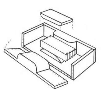
a marker during the flnal machlneing stage.After the sealing operation is completed, the block of ice is placed In the centre of a specially designed box as shown in Figure
Figure 2. Pin -loaded tension specimen. B,W,A s 10d (grain size)
Figure
3.
A specimen (without holes) with gauge section made of transparent freshwater ice4. End sections are
men
bullt up by successively adding layers of foe, about 10 rnm in thickness, using an ice-water slurry made of distilled and de-aemed water and fine-grained Ice seeds that passed throu h a standard sieve with a mesh sire of 1mrn.
This prmess is aiopted to protect the test section from pressures that could develop during freezlng and could indue0 microcracks. To rnin~mize the rnachinelng time and to avoid unwanted warming effects that could induce brine drainage. spacers are used in the b o x as shown. To prevent adhesion to the box, the walls of the box and the surfaces of the spacers are lined with a layer of thick polyethylene. When the freezing p r m s s Is complete, the ice block can be removd easily by unscrewing the two side panels of the box.Figure 4 Special box for fabricating the specimen
The final dog bone-shaped specimen is then repared usinq a
milling machine inside the same cold room used f!r the fabrication process. Care
is
takentu
remove completely the layer of paperand ice used for sealing. A drlllinq machine, in conjunction with a
jig b3 hold the specimen,
fs
then used for making holes In the twoend sectlons of the specimen and on the iongltudinal axis of the specimen. Any cutler marks on the Instde surface of one of the end holes are removed b inserting the pin, at a temperature of slightly above O°C, end a l h w the speamen to hang and swlng freely, In a vertical position from the pin holder attached
to
the upper ~fllversal joint In the tsst machine, until the pins are cold and the melted thin layer ofIce
are frozen. This operation Is repeated for the othar end of the specimen. These procedures are followed to insure g o d fit and rotational movement of the specimen around the loading pins. Cutter marks on the surfaces in the gauge section of a speclmen arethen
remwed carefull with finesandpaper followed by a polish with tissue paper slight$ rnolrtened (not soaked) with alcohol. Although the m~lling operation can be
performed wlth an accuracy of 0.02 mm, the ends of the specimens ars symmetrical Tn width w M the centre line of the reduced section within about 0.5 rnm (see ASTM,1987).
Test Procedure
A commercial closed-loop, servoh draulic system (MTS) of 1.0 MN capacity situated inside a cok! room near an observation window is used. The cold room is maintained at a temperature of -10°C
f
0.l0C and .the. controls, pump, and all of the recording system are kept outslde In a warm room.The h a n g traln consisbs of two mmmerclalty available universal tenslon joints and two specially desfgned tenslle pln holder-unhrersal
Blnt
systems(one at
thetop
and one at the bottomof the specimen, Figure 5) and a 250-kN capacity load cell. 7ha
specimen holders are designed
to
allow a small confining pressure(if required) through
a
set of parallel plates, covered with thick layers of polyethylene sheets, and screws (Figure 6). The bwer holderis
attached to tha actuator and theu
per holder issuspended from the cross-had via the load cell.
T R ~
rnachlnacan
b programmed to ply varlous amounts
aM
rates of load, strain, and displacement. X i a l strain rats.f ,
is maintained constantby
afeedback system emplo ing a 150 rnm (or 200 mm) gauge-length extensometer attached drectl to the central area of one face in the gauge section (Figure 6).
he
extensometer is mounted on thespeclmen
uslng two
specially designed metal holders (details givenin Sinha, 1986) frozen to the top and the bottom of the gauge section of the specimen. Load and strain outputs are remrded separateb, as functions
of
time, on strip chart recorders and on a dlg~lal data loggingsystem
outside the cold room.After completion of a test, two thin sections are made from the tested ice
-
to examine the vertical as well as the horizontal profile of the grain structure. Thin sections, about 0.5 mm in thickness, are prepared by the double microtome technique develo ed speci ica ly for sea ice .and described in detail in Sinha (1977). !he main advantage of thls method lies in the clarity with wh~ch theFigure 5 One of the two universal tensile joint and pin holder systems used in the load train
Figure 6 A multi-year sea ice specimen before test (a) and after test (b)
microstructure of sea ice can be examined; conventional methods, commonly practised in ice laboratories, disturb the microstructure and often add artifacts.
About a third of the gauge section of the specimen is melted after testing to determine the salinity of the ice. These measurements, along with the salinity measurements obtained before the tests, allow one to check whether the salt content of the ice has changed as a consequence of the fabrication and testing procedure. It should be mentioned here that the large core provides plenty of ice, in addition to the specimens, to carry out pre-test salinity profile and microstructural studies similar to the description given in Bjerkelund et al (1985).
MULTI-YEAR SEA ICE
0.75
Flgure 9a shows a mid-plane thin sectbn of the specimen in Figure 6. Thls thin section was prepared by the dwble- mlcrotoming technique developed earlier to avoid tho artifacts that are intrcduced by the usual thin sectioning meth* (Sinha, 1977).
The photograph of the section under cross-polar~zed light shows that the ice had
a
preferred orlentation wih the c-axis ot thesub
grains tended to
be
parallel to the long axis of the speclmen and hence the direction of the load application. The bullt-u Ice filling the saw-Toothed section of the original rough cut can 1 s seen at the lower end of the photograph. Note the granular ~ c e wlth small grainsizes,
less than 1 mm, in the addedend
section.The location of the fracture surface is revealed in the
MULTI-YEAR SEA ICE -1O0C,
L =
1 x lo's-'0.75
TIME, s
2 TIME, 10 .s
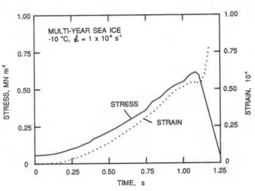
Figure 7 Stress and strain history for a tensile test on multi- Figure 8 Stress and strain history for a tensile test on yulti- year sea ice at a strain rate of 1 x 10
*
s.' year sea ice at a stra!n ra!e corresponding to the speclmen In Flgure 6 of 1 x 10 s"Results
Using the l8chnfques described e v e , tests have been conducted successfully in
a
wide range of strain rates. An
example of a test result of multl-year
ice
at a strainrate
of 1 xlo6
s" IS shown in Figure 7. The lrneariiy in the straTn history shows
that the test
s
stem responded well.me
stress history, however, indicated that t(e ice responded in a rsthsr nonlinear rnannsr,Figure 8 shows test result at
a
strain rate of 1 x 10⁴s".
Itcan
be seen that the test system reacted rather slowly and took a b u t 0.5 sewnds before it could impose the specified svain rate. Such a lack of control in the testsystem
can not be revealedby
the custornaty stress-straln diagram ashas
been polnted out earlier (Sinha, 1981). This was one of the worst cases recorded duringme
tensile tests. This example Is reproduced here to show the limitations of even a well-tuned closed-looped system. It was shown earlier during compression tests, where the load train was relatively slmple, that thes
stem could operate well upto
a strain rate of 2 x 10⁻³ s-t ( ~ i n K a , i g ~ ) and that thes
smm requiredabout 40 milliseconds to respond (Sinha, 19883. The slow response in the present case of tensile tests could be due to the added sofb7ess and the compfexities of the load train used. More studies are required to wnf~rm this point
The state of lhe speclmen h f o r e and
after the
test, con'asmndina to the test in Flaure 8. are shewn in Fiaure 6. Ithay be seeii that the fracture"muribd in the gauge section. A H
single crack, formed in the lower half of the specim~n, caused (a) I0 mm (b)
fatlure, In this case the specimen was orlented in the horizontal
plane and the gauge smtlon had a dimension of 50 mm x 100 mrn Figure 9 MMplane thin ~ 9 ~ t i o n
of
the
Speclmen R Figure 6x
150 mrn with the 100 mm x 150m m
face parallel to the plane of after test obsenred under cross-polarlzed light (a) the ice mver andnormal
to the length of the columnar grains. and under scatlered light (b).macrograph (Figure
9b)
taken under scattered llght Sinha, 1977). The entrapped ~mpurities atxl the voids in the Ice Inc1
uding a brlne channel are made visible by this method. Note that the crack passes through a large clrcular void on the left of the specimen. lgure 10shows
a
photograph taken using a combined scattered- light and polarized-lfght techn~ ue (Sinha.1981). Many details of the structure and the texture of %e ice are made visible. It w n beseen that the small chan~es in the orlentation of the crack was- Influenced by the rnicrosbicture. On the left hand side near its probable origin at the circular voids, the crack propagated parallel to the sub-gfaln boundaries. The figure also shows that the
crack
became trans-sub-granular as it progressed to the right hand side. This transcrystalline characteristics oi the
crack
propagation can beseen clearly in the micrograph shown in Figure 11. In this rnicrwraph the sub-grain boundaries are revealed by thermal etching following mrcrotoming (S~nha, 1986). It should be mentioned here that the microstructural details described h v e can
not
be
revealed by the mnventional thin sectioning andphotographing methds. In all the photographs illustrated by Dykins
(1967, 1969, 1970), for examples, the fracture planes in columnar- grained saline ice were shown as bands, up to 5 mm wide, of fine- grained granular ice.
b naw method
has
been develapttdtu
fabricate dumbell- or dqbone-type spaefmens with ends madeof
built-upIce
and
gauge sections made of ice to be tested In tenslon. Using this techniqueit is possible
to
test manytypes
of natural ice if the available iceblock for tesHng is larger than the she nemssarj for the required gauge sections. Tbe gauge sections are made to be large enough to contain a sufficient number (greater than ten) of gralns across their width, to amid
any
geometric effect, and long enough to Installa large displacement gauge (longer than ten grain diameters) directly on the ice in the gauge section. The spedrnen geometry is
suftable for tensfle testing under closed-loop controlled constant strain rate loading cond~tions with the controlling displacement gauge mounted directly on the spwimen. S ecirnens with cylindrical gauge sections can be made for isotrcpl)c, granular ice w~th equiaxed grains. For coiurnnargrained ice,
however,
prismaticgauge sections with rectangular cross-sections are more compatible with the geometry of the grains
than
are circular cross-section.Figure 10 Mid-plane thin secnon or me speclrflen in Figure 6 Figure 11 Details of the crack near Ule center of the thin after test photographed using a combined scattered- section in Figure 10. Sub-grain boundaries are light and polarized-light technique. revealed by etching.
Acknowledaements Hawkes, I.
ahd
Mellor, M. 1972). Deformation and Fracture of IceI
Under Uniaxial Stress. J. G aciolony, 11 (61).
pp.
103-131. The author is indebted to R. Jerome for his assistance in allphases of this work. Jones, S.J., and Chew, H.A.M. 1981). On the Grain-size De endence of Secondary Creep. J. Dlaciolmv. 27 (871, pp. 517- 51
I.
References
ASTM (1987). Standard Methods for Tenslon Testing of Mstanle Materials (Mehlc
J
.
DesI nation: E8M-86,
Volume 03.01, pp. 199-222; Standard
ractice
$r Conducting %mep. Cr@eprupture, and Stress-rupture tests of Metallic Materials, estgnatron: E l 39-83, Volume 03.01, pp. 441-455.Bjerkelund, C.A., Lapp, D.J., Ramseier, R.O., and Sinha, N.K. (1985). The Texture and Fabric of the Second Year Sea Ice Cover at Mould Bav. Prince Patrick Island. NWT. ADril. 1983. Proc. 1 9 S IEEE Int. Geoscience and Remote. sensing ' S V ~ ~ D ;
GAR%
'85-
University of Massachusetts. Amherst MA. Oct.7-9, 1985. DigeA Vol.1. pp. 426431.
Burdldr, J. L. (19751, Tensile Cre rupture of Polycrystalllne Ice.
P m .
3rd.Int.
Conf. on Port and %an Enalneerina under Arctic on itons P Rai
anks, Alaska, University of Alaska. 77-15kgtsi.
1 d 5 .?pch3g+2?6.Chen, A.C.T. and Lee. J. (1986). L e-Scale Ice Strength Tests at
slow stran =ate=. ~ m c . 5th Int.%mp. on ~ l s h o r e Mechsnia
and Arctic
E
~neerin MAE,
Apr~l 13-18, 1986, Tokyo. Japan,m ~ e
Zh.
w VoIP4,';. 37i-378.Dyklns, J. E. (1987). Tenslle Properties of Sea
Ice Grown
In
aConfined System. P m . Int. Cgnf. on Low TemDerature S c l e ~ e , Sapmro, Japan: Phvslcs of Snow
artd
Ice, e d i t 4 by H. b r a ,Insh'tute
of
Low
Temperature Science, Hokkaldo University, Vol.1,Part 1. pp. 523-537.
Kuehn, G.A., Lee, R.W.,.Nixon, W.A., and Schulson, E.M. (1988). The Structure and Tens~le Behavlour of First Year Sea Ice and ~aborat&-G&n Saline
19.
Proc. 7th Int. Conf. on Offshore Mechanics and Arctic E n a l n e e n i i Texas. Publishedby
ASME. New York. Vol.1, pp. 11-17.Lee, R. W. (1986). A Procedure for Testing Cored Ice Under Uniaxial Tension. J. 32 (1 12), pp. 54041.
Peyton, H. R. 1966). Sea
Ice
Stren th. Geoph sical Institute,I,
University of Alas
a
Fairbanks, Alaska,kmt
No.JAG
R-182. Saeki, H.,Nomura,
T.,and
Ozakl, A. 1978). Ex rlmental Study on the Testing Methods of strength and ~~hen1csP"Propema for SeaIce. Prm. IAHR S y m ~ s l u m on Ice Problems, Aug. 7-9, 1978. Lulea Sweden, Part 1 , pp. 135-149.
Sinha, N.K. 1977). Technique for Stu ing Structure of Sea Ice. J.
Glaciolw, Jol. 18. No. 79, pp. 3 1 5 - 3 8
Sinha, N.K. (1978). Rheology of Columnar-Grained Ice. Ex~erimental Mechanics, 18 (1 2), pp. 464470.
Sinha, N.K. 1981). Rate Sensitivi of Compressive Strength of Columnar-Grdned Ice. Emerimenta? Mechanics, 21 (61, pp. 209- 21 8.
Sinha, N.K. (1984). Uniaxial Corn ressive Strength of First-Year and Multi-Year Sea Ice.
Can.
11(1,
pp. 82-91.Dykins, J. E. (1969). Tensile and Flexure
Pm rtfes
ofSahe Ice.
Sinha, N-K. (1986)- Young Arctic Frazil Sea Ice: andProc.
Int
Laboratory Strength Tests. Journal of Materials Science. Vol. 21.Buliemer and
I-!.
Engelhardt, Plenum NO. 5. May 1986, PP 1533-1546-Sinha N.K.,
Strandberg,
A. and Vij, K.K. (1986). In Situ Assessment Dykins, J. E. (1970). .Ice Engineering-
Tensile Properties of Sea of Drillin Platform Sea Ice Strength Using a Bor*ole Jack- Proc. Ice (3-n m, a Confined S stem. Technical Re .rt R689. NavalFGkr$"B:m27"-"2t
Fz:g:~hy$
3 $ & ~ ~ ~ r $ ~ ~ ~ ~
Civil Ena~neer~na Laboratow, %ort Hueneme, ~a11foE1a.
Canadian Geotechniml Socletv,
. .
pp. 153-1 57.E&t.
H.
(1%). Creep Tests wm !=men Soils Unar TensionSinha N.K.
(18881.
ExperimenUIon
Admom Rate ledtlveand Uniaxm ession. Pm. Permafm=t
Conh
Strain RaM and Modulus of &brnnarqrained
19.
PIDF. 7th Ink Cal a Canada:R e
Ro r. .
tuwn ernorld Volume e it$,
a$:
French, A ~ s C C i a f ~ ~ ~ m i ~ e e OnMGeOtecnnicalR;setr,-hq
""1.
7-12, on Houston, Oflsh~re Texas,