Design of Load-lock Door for Unit Dose
Continuous Lyophilization Process for Complex Biologics
by
Ryan Maximiliano Flores
Submitted to the
Department of Mechanical Engineering
in Partial Fulfillment of the Requirements for the Degree of Bachelor of Science in Mechanical Engineering
at the
Massachusetts Institute of Technology
May 2020
© 2020 Massachusetts Institute of Technology. All rights reserved.
Signature of Author:
Department of Mechanical Engineering May 11, 2020 Certified by:
Alexander H. Slocum Walter M. May and A. Hazel May Professor of Mechanical Engineering Thesis Supervisor Accepted by:
Design of Load-lock Door for Unit Dose
Continuous Lyophilization Process for Complex Biologics
by
Ryan Maximiliano Flores
Submitted to the Department of Mechanical Engineering on May 11, 2020 in Partial Fulfillment of the
Requirements for the Degree of
Bachelor of Science in Mechanical Engineering
ABSTRACT
The process of unit dose continuous lyophilization consists of moving vials containing unit doses of pharmaceutical product though a series of process chambers with varying pressures and temperatures. In order to move the vials between process chambers with varying pressures without disturbing the conditions within each respective chamber, a load lock is required. Although load locks are commonly used in the semiconductor industry, existing designs are not directly applicable to the unit dose continuous lyophilization process due to the unique geometric constraints on the system. This thesis document details the design of a load-lock door for the unit dose continuous lyophilization process. To meet the load-lock door functional requirements, a four-bar linkage load-lock door and a load-lock door with ground pivots offset from the sealing surface were designed. Because the driving performance parameters cannot be reliably modeled, the seal performance, particle generation, and seal adhesion of each design will be experimentally tested. The highest performing design will be chosen and improved based on the experimental results.
Thesis Supervisor: Alexander H. Slocum
Acknowledgements
I would like to thank Prof. Alexander Slocum for his guidance and input throughout the design process. I would also like to thank Serena Le for all her patience and dedication to success throughout the project, as we worked on our designs in parallel. Additionally, I would like to thank the whole lyophilization team for their help throughout the project.
Table of Contents
Abstract Acknowledgements Table of Contents List of Figures List of Tables List of Symbols 1. Motivation 13 2. Background 132.1 L-Motion Type Gate Valve 13
2.2 Gate Valve with Three-dimensional Seal Geometry 14
2.3 Angled Gate Valve 16
2.4 Linkage-type Gate Valve 16
2.5 Bonded Seals for Gate Valves 17
3. Scope 18
4. Design 18
4.1 Functional Requirements 18
4.1.1 Load-lock System Level Functional Requirements 18
4.1.2 Load-lock Door Functional Requirements 19
4.2 Risks and Counter Measures 20
4.2.1 Adhesion 20
4.2.2 Particle Generation 21
4.2.3 Leak Rate 21
4.2.4 Effect of Pressure Differential on Sealing 21
4.3 Design Parameters 22
4.3.1 Investigated Design Directions 22
4.3.2 Final Design Direction 24
5. Analysis 25
5.1 Four-bar Linkage Synthesis 25
5.2 Linkage Layout on Structure and Linkage Drive Mechanism 33
5.4 Sizing Linkage Actuator 38
5.5 Structural Analysis of Pivots, Links, and Drive Shaft 43
5.6 Sleeve Bearing Lifetime and Wear 48
6. Conclusion 51
7. Future Steps 51
8. Appendix 53
8.1 Appendix A: MATLAB Code for Linkage Kinematics 53
8.1.1 MATLAB Code 53
8.1.2 Diagram detailing Parameters used in MATLAB Code 55
8.2 Appendix B: Force and Moment Balance on Door and Links 56 8.2.1 Force and Moment Balance on Door and Links during Initial Sealing 56 8.2.2 Force and Moment Balance on Door and Links when Breaking Seal 57 8.2.3 Force and Moment Balance on Door and Links for Pure Rotation 58
8.2.4 Diagrams Associated with Force and Moment Balances 58
List of Figures
Figure 1: Drawing of L-motion type gate valve depicting its operation [12]. 14
Figure 2: Solid model of “MONOVAT” gate valve with 3D seal geometry [23]. 15
Figure 3: Drawing of gate valve with three-dimensional seal geometry [21]. 15
Figure 4: Drawing of angle gate valve [15]. 16
Figure 5: Drawing of linkage-type gate valve [22]. 17
Figure 6: Image depicting a seal bonded to a metal substrate [20]. 18
Figure 7: Diagram showing one load-lock cycle. 19
Figure 8: Hierarchical chart showing the investigated load-lock door design directions
defined by their type of motion. 22
Figure 9: Diagram showing the position of the existing pivot from the load-lock door with pivot close to sealing surface and the possible locations for the second pivot. 26 Figure 10: Diagram showing the possible locations for ground link pivots and required seal
contact locations on the sealing structure. 27
Figure 11: Diagram representing the door in its first-desired state, sealed to the sealing
structure. 28
Figure 12: Diagram representing the door in its second-desired state, lifted off the sealing
surface. 29
Figure 13: Diagram representing the door in its third-desired state, opened to allow the mover loaded with vials into the load lock. Lines connecting pivots in each state and
respective perpendicular bisectors are shown. 30
Figure 14: Diagram showing the locations of the ground pivot points, which are defined by the intersection points of the perpendicular bisector corresponding to each pivot point on the
door. 31
Figure 15: Diagram defining the links that make of up the four-bar linkage. 32 Figure 16: Plot showing the trajectory of the top and bottom seal contact points throughout the full-theoretical motion of the four-bar linkage, see Appendix A for MATLAB code used to generate plot. The red arrows represent the direction of travel of the door during closing.
33 Figure 17: Side and front views of four-bar linkage design solid model, showing the linkage
Figure 18: Isometric view of load-lock door with pivot offset from sealing surface, showing
the pneumatic drive mechanism used for both designs. 35
Figure 19: Front view of O-ring sitting in half-dovetail groove in load-lock door. The O-ring
cross sectional diameter and bend radius is shown. 36
Figure 20: Free-body diagram of load-lock door. 38
Figure 21: O-ring Compression Force for .210 Cross Section O-ring [9] 40
Figure 22: Logarithmic curve fit to O-ring compression force for .210 cross section O-ring 41
Figure 23: Diagram showing beam bending of cantilevered pivot. 44
Figure 24: FEA results for directly driven crank link for linkage design, showing von Mises
stress. 45
Figure 25: Diagram showing torsion of drive shaft. 46
Figure 26: FEA results for drive shaft, showing von Mises stress. 47
Figure 27: FEA results for directly driven crank link when pinned to door, showing von
Mises stress. 48
Figure 28: Free-body diagram of door, for linkage design. 58
Figure 29: Free-body diagram of door, for pure-rotation design. 59
Figure 30: Free-body diagram of shaft driven crank link, for linkage design. 59 Figure 31: Free-body diagram of shaft driven crank link, for pure-rotation design. 59 Figure 32: Free-body diagram of directly driven crank link, for linkage design. 60 Figure 33: Free-body diagram of directly driven crank link, for pure-rotation design. 60
List of Tables
Table 1: Pugh chart showing the criteria used to choose a load-lock door design direction 24
Table 2: Leak rate calculation 37
Table 3: Initial squeeze calculation 39
Table 4: Force required to achieve initial squeeze calculation 42
Table 5: Force required to open door when O-ring has adhered to sealing surafce calculation 43
List of Symbols
Page 37F permeability of the rate of the gas through the elastomer at the anticipated operating temperature [cc*cm/(cm2*sec*bar)]
D inside diameter of the O-ring [inches] L approximate leak rate of the seal [cc/sec] P pressure differential across the seal [lb/in2]
Q factor depending on the percent squeeze and whether O-ring is lubricated or dry S percent squeeze on the O-ring cross section expressed as a decimal
Page 42
Wchord chord width of the O-ring at the sealing surface
Doring cross sectional diameter of the O-ring
Sresidual residual squeeze left when pressure is equalized
Asqueeze contact area between the O-ring and the sealing surface
Loring total length of the O-ring
ΔP maximum pressure differential across the seal
Fopen force required to open the door when the O-ring is adhered to the sealing surface
Page 44
Ishaft moment of inertia of the shaft
Dshaft diameter of the shaft
σbend maximum bending stress on the shaft
Fpivot radial force on the pivot
Lapplication distance from the fixed end of the shaft to the location of force application
σyield yield stress of the shaft material
Safety Factorbend safety factor on bending stress before yielding occurs
Page 46
Ipolar polar moment of inertia of the shaft
SCFkeyway stress concentration factor due to the keyway
Dshaft diameter of the shaft
τshear maximum torsional shear stress on the shaft
Tdrive torque on the shaft
σyield yield stress of the shaft material
Safety Factorshear safety factor on torsional shear stress
Page 48
Δϴ change in angle of the link between closed and open positions of the door [radians] D inside diameter of the bearing [mm]
F radial force on the bearing [N] L length of the bearing [mm] P pressure on the bearing [N/mm2]
t time it takes to close or open the door [sec] V sliding speed at the bearing surface [m/sec]
Page 49
W estimated wear dimension [mm]
K specific wear amount [mm3*sec/(m*N*hr)] P pressure on the bearing [N/mm2]
V sliding speed at the bearing surface [m/sec] T sliding time [hours]
N number of load lock cycles in its lifetime T time it takes to close or open the door [sec]
1. Motivation
The process of unit dose continuous lyophilization consists of moving vials containing unit doses of pharmaceutical product though a series of process chambers with varying pressures and temperatures. The changes in temperature and pressure induce the necessary changes in the product to achieve its final state. In order to move the vials between process chambers with varying pressures without disturbing the conditions within each respective chamber, a load lock is required. Load locks are regularly used in the semiconductor industry to move semiconductor wafers between process chambers. However, the load-lock door designs used in the semiconductor industry cannot be directly used in the continuous lyophilization process because of how vials will be moved between process chambers. The vials will be moved through process chambers on movers. To allow the movers to travel through the process, the maximum gap between consecutive process chambers is 10 mm, and the transition between process chambers must be flat. The load-lock door designs used in the semiconductor industry are operating under a different set of design constraints, which allows for gaps larger than 10 mm between process chambers and wafers to be passed over height differentials between process chambers. As a result, a load-lock door needed to be designed to suit the continuous lyophilization process.
2. Background
2.1 L-Motion Type Gate Valve
L-motion type gate valves are used in the semiconductor industry for separating load locks and process chambers [18]. These gate valves are described as having an L-motion because when closing, the valve blade first moves parallel to the valve seat. Then, once the valve blade has moved into place over the opening in the valve housing, the valve blade moves normal to the valve seat sealing the valve [12]. The opposite motion occurs for opening the door. The L-motion is achieved using a cam mechanism. The L-motion is critical because it eliminates sliding between the seal on the valve blade and the valve seat, minimizing particle generation [12]. Because of the seal’s orientation with respect to the chamber, a pressure differential can be used to help provide the force necessary to squeeze the seal. L-motion type gate valves are commercially available from several companies such as VAT [18] in sizes suited for the semiconductor industry. However, they
Figure 1: Drawing of L-motion type gate valve depicting its operation [12].
2.2 Gate Valve with Three-dimensional Seal Geometry
Used between process chambers and load locks in the semiconductor industry, gate valves with three-dimensional seal geometry are unique because they only require linear motion to seal the valve. The valve seat and gate have corresponding three-dimensional mating geometry [21]. These types of gate valves are simple to actuate using a pneumatic cylinder [19], but the complex sealing profiles can be challenging to manufacture. Because the sealing direction is perpendicular to the chamber opening, a pressure differential cannot be relied on to provide the force necessary to squeeze the seal. The gate must be supported by the valve seat to prevent deflections of the gate that reduce sealing performance when the gate valve is subject to a pressure differential. This valve was considered for the lyophilization system, but would require a molded seal as the space available to machine the surfaces to accommodate use of a conventional O-ring was deemed not feasible.
Figure 2: Solid model of “MONOVAT” gate valve with 3D seal geometry [23].
2.3 Angled Gate Valve
The angled gate valve aims to eliminate the need for any bearing surfaces within the semiconductor process chamber and reduce the amount of force required to seal the door [15]. Similar to the gate valve with three-dimensional seal geometry, the angled gate valve only requires linear motion to actuate the gate. The angled gate valve uses a simple face seal geometry, which reduces the manufacturing complexity compared to the three-dimensional seal geometry. Because the actuator applies force normal to the sealing surface, all of the applied force is translated into sealing force. In addition, all of the sliding interfaces in the mechanism are sealed by a bellow sleeve, preventing particle contamination. For the lyophilization chamber system, this design has potential.
Figure 4: Drawing of angle gate valve [15].
2.4 Linkage-type Gate Valve
The valve closure mechanism for semiconductor deposition apparatus utilizes an articulated linkage to open and close a valve which rotates about a shaft [22]. Instead of using a wedge and roller to provide the force required to seal the cover plate like the prior art, the valve closure mechanism uses the small change in angle between the two links at the end of its travel to generate the large force required to seal the cover plate. The linkage eliminates the need for the wedge and roller which resulted in particle generation and instead uses rolling contact bearings
which can be sealed to reduce particle contamination. For the lyophilization chamber system, this design has potential.
Figure 5: Drawing of linkage-type gate valve [22].
2.5 Bonded Seals for Gate Valves
Instead of O-ring seals, bonded seals are often used in gate valve applications. Instead of an O-ring sitting into a dovetail groove, the seal is vulcanized to the metal door [20]. Because the movement between the seal and the groove is eliminated, particle generation is greatly reduced, and the lifetime of the seal is increased [20]. Additionally, bonded seals eliminate the problem of an O-ring being pulled from its groove if it has adhered to the sealing surface. However, bonded seals are not ideal for prototyping because it is expensive to have custom gates with bonded seals manufactured at low volumes. For a production level system, a molded seal can be used once the concept has been proven using an O-ring.
Figure 6: Image depicting a seal bonded to a metal substrate [20].
3. Scope
This thesis documents the design of a load-lock door for unit dose continuous lyophilization process. In parallel, a fellow student Serena Le, has also designed a load-lock door for unit dose continuous lyophilization process. Because several critical parameters that affect load-lock door performance such as particle generation and seal adhesion to sealing surface cannot be accurately modeled, hardware testing is the most effective way to determine which of the two load-lock door designs will perform the best. As of April, 30, 2020, part drawings for both load-lock door designs have been sent out for manufacture, and the performance of both designs will be evaluated once the parts are manufactured and assembled.
4. Design
4.1 Functional Requirements
4.1.1 Load-lock System Level Functional Requirements
To ensure the load lock functions properly as a subsystem of the continuous lyophilization process, a set of functional requirements for the load-lock system was developed. On a high level, the load lock must allow selective access to the two process chambers on either side of the load lock. The internal volume of the load lock needs to be pumped down or vented to match the pressure on either side of load lock, as seen in Figure 7. To prevent contamination of the product inside the vials and maintain cleanliness of the system, particle generation during the operation of the load lock must be minimized. In order to maintain the desired throughput during the continuous lyophilization process, the operation of the load lock must be as fast as possible. The load-lock design must be robust, to minimize interruptions to production caused by servicing of components.
Figure 7: Diagram showing one load-lock cycle. 4.1.2 Load-lock Door Functional Requirements
The most critical module of the load lock is the door, as a result, the following design process is focused on the load-lock door. A set of functional requirements specific to the load-lock door was derived from the load-lock system functional requirements:
1. Load-lock door maintains pressure differential of 101,324 Pa between process chamber and load lock with a maximum leak rate of 10-4 cc/sec.
2. Load-lock door opening allows mover loaded with vials with an overall width of 107 mm and height of 62 mm to move into load lock.
4. Load-lock door and complementary sealing structure do not affect motion of movers by maintaining a maximum gap of 10 mm and a flat transition between load lock and process chambers.
5. Load-lock door actuation time is less than 5 seconds.
6. Load-lock door must be able to withstand exposure to environmental conditions within process chambers and during washdown.
7. Lifetime of load-lock door is greater than 100,000 cycles before service is required.
4.2 Risks and Counter Measures
The potential risks associated with the load-lock door design were identified and are discussed in this section. Countermeasures were developed from the onset of the design to ensure the risks do not affect the performance of the final load-lock design.
4.2.1 Adhesion
One phenomenon associated with elastomeric seals is adhesion. Adhesion is when an elastomeric seal such as an O-ring seal adheres to its sealing surface due to secondary bonds such hydrogen bonds and Van der Waals attractions formed between the O-ring material and sealing face [16]. When a seal with a large contact area adheres to its sealing surface, a large force is required to unstick the seal. As a result, there is a possibility that adhesion will necessitate large forces to unstick the load-lock door after it has been sealed, especially for an extended period of time. Common methods for combating adhesion include sealing surface improvement such as applying surface coatings and tuning surface finish. In addition, the seal polymer can be chosen to minimize adhesion [16]. Regardless of the implementation of these common solutions, adhesion is not a well understood phenomenon and is not easily modeled, so the actuator used to open the door will need to have a large safety factor on the force it can supply to ensure it will be able to unstick the door. Additionally, the load-lock door can be designed in such a way that only part of the seal is unstuck from the sealing surface at a time. This can be achieved by implementing a peeling motion instead of lifting the door directly off the sealing surface all at once.
4.2.2 Particle Generation
Another risk associated with the load-lock door is particle generation. Particle generation occurs when components slide against each other. Sliding can occur between mechanical interfaces such as a pin rotating in a bushing, but small-scale sliding can also occur between components when there are movements between components due to deflections under load. The generated particles can contaminate the pharmaceutical product and compromise the cleanliness of the continuous lyophilization process. To mitigate this risk, the number of sliding interfaces in the load-lock door mechanism need to be minimized, and the necessary sliding interfaces need to be sealed to prevent particles from entering the pharmaceutical product.
4.2.3 Leak Rate
No matter how well a seal is designed between two environments with different pressures, leakage will occur from high pressure to low pressure. In the case of the load lock, if the leak rate through the door seal exceeds the vacuum pump’s ability to remove air from the load-lock, the pressure inside the load lock will not reach the desired vacuum. Several parameters related to seal design affect the leak rate including permeability of the seal elastomer, length of the sealing surface, lubrication of the O-ring, and percent squeeze [9]. To ensure a tolerable leak rate through the load-lock door seal, the total length of the seal should be minimized to reduce the probability of the existence of defects along the seal path. The seal with the largest effective width, in the case of an O-ring the largest possible cross-section diameter, should also be chosen to increase the length gas has to travel through the seal interface before it passes through to the other side. In addition, the appropriate seal material should be chosen to minimize permeability, and the seal groove geometry should be designed to optimize squeeze.
4.2.4 Effect of Pressure Differential on Sealing
Due to the large pressure differential across the load-lock door, the door will experience high forces on its surfaces with large area. If designed improperly, these forces can cause deformations of the door and sealing surface causing leaks. As a result, the load-lock door and structure must be stiff enough, so that forces due to the pressure differential do not cause
seal, or it can oppose the necessary sealing force. The door should be oriented so the pressure differential aids in squeezing the seal, so a prohibitively large actuator is not required to oppose the pressure differential to maintain squeeze on the seal.
4.3 Design Parameters
In order to meet the load-lock door functional requirements, a number of different design directions were investigated and evaluated based on seal performance and risks associated with each design.
4.3.1 Investigated Design Directions
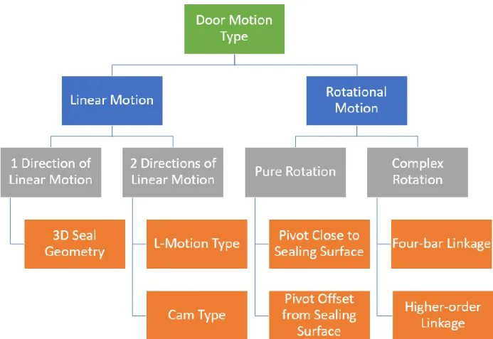
The design directions were categorized by the motion of the door when moving from open to closed positions or vice versa.
Figure 8: Hierarchical chart showing the investigated load-lock door design directions defined by their type of motion.
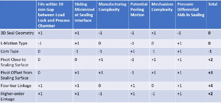
A total of seven design directions were investigated to determine which designs should be pursued. Although, all of the design directions have their merits in different applications, only three of the design directions were designed for hardware testing. The three-dimensional seal geometry solution was inspired by the MONOVAT transfer valve used in the semiconductor industry [19]. Due to the complexity and cost to manufacture the three-dimensional seal groove at low volume, this door design was not chosen. L-motion type transfer valves are also regularly used in the semiconductor. However, an L-motion type door was not chosen for this application because it did not fit in the 10 mm gap between load lock and process chamber [12]. The cam-type door uses a track on either side of the door much like a garage door which cams the door against the sealing surface at the end of its travel. This design was not chosen because it necessitates small-scale sliding between the seal and sealing surface during the cam action. Additionally, the tracks encroach on the usable space in the process chambers when door is in the open position. Linkage designs with greater than four links were investigated, but the complex motions they offered did not provide significant benefit over the simpler four bar linkage. By the principle of Occam’s razor [7], these higher order linkages were not pursued further.
Table 1: Pugh chart showing the criteria used to choose a load-lock door design direction
4.3.2 Final Design Direction
The three designs chosen for hardware testing were: 1. Simple pivot close to sealing surface
2. Simple pivot offset from sealing surface 3. Four-bar linkage
Serena Le, a fellow senior, designed a load-lock door with pivot close to the sealing surface for her SB thesis. This thesis documents the design of a four-bar linkage load-lock door which can be simplified into a load-lock door with pivot offset from the sealing surface by removing the follower link and locking the crank link to the door. Each of the three designs will ultimately be tested to determine which one performs the best in terms of sealing performance, minimizing particle generation, and reducing force required to break seal after adhesion.
An advantage of the four-bar linkage design over the pure rotation (simple pivot) designs is using a four-bar linkage allows the motion of the door to be tuned to minimize sliding between the seal and sealing surface and/or introduce a peeling motion to reduce the effects of adhesion. Additionally, the motion of the door can be tuned to minimize the required gap between load lock and process chamber. For this application, the linkage was tuned solely for minimizing sliding
because the four-bar linkage is actuated using a pneumatic cylinder which can be oversized to ensure enough force is applied to the linkage to open the door when the seal is adhered to the sealing surface. Additionally, many of the four-bar linkage designs that include a peeling motion use a singularity close to where the door has reached its closed position. Although this singularity is beneficial for introducing a peeling motion, there is a risk that this singularity can cause the linkage to jam, so a peeling motion was not used in the final linkage design.
5. Analysis
The following chapter details the analysis required to design the four-bar linkage load-lock door and the load-lock door with pivot offset from sealing surface.
5.1 Four-bar Linkage Synthesis
The motion of the four-bar linkage is designed to reduce sliding between the seal and the sealing surface. Because a fellow student (Serena Le) is working on the load-lock door with pivot close to sealing surface, a set of constraints were imposed on the linkage design to ensure that both designs can be tested using the same sealing structure and door. The set of constraints on the linkage design is:
1. The same door is used for all three designs.
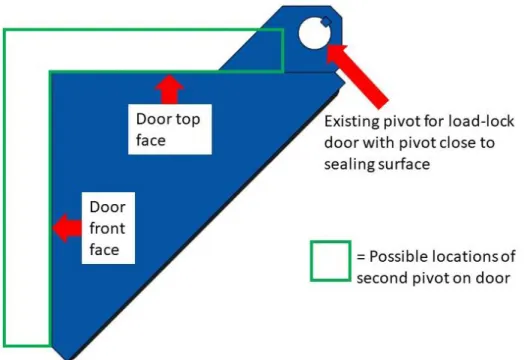
a. The pivot used for the load-lock door with pivot close to sealing surface is used as a pivot for the linkage design to minimize geometric complexity of the door. b. The second pivot location on the door must be located on the top or front face of the door due to limited clearance between side faces of the door and walls of the sealing structure.
2. The same sealing structure is used for all three designs.
a. The O-ring seal on the door contacts the sealing surface in the same location for all three designs.
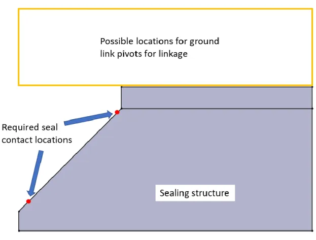
b. The ground link pivots for the linkage must be mounted onto the existing sealing structure in a location that doesn’t interfere with the other designs.
Figure 9: Diagram showing the position of the existing pivot from the load-lock door with pivot close to sealing surface and the possible locations for the second pivot.
Figure 10: Diagram showing the possible locations for ground link pivots and required seal contact locations on the sealing structure.
After identifying the coupler link constraints on the linkage design (shape of door and where pivots can be located), the three-precision point method was used to synthesize the location of the four-bar linkage ground pivots and crank and follower link geometries [7]. Although the three-precision point method is shown as a linear process, several iterations were required to arrive at the final design. The implementation of the three-point precision method is detailed below:
1. An outline of the sealing structure is drawn, and points are placed on the sealing surface where the O-ring seal will contact the sealing surface when the door is in its closed position. A point is then placed where the existing pivot on the door will be located when the door is in its closed position. Then, the second pivot location on the door is
chosen within the constrained area. In the final iteration, the second pivot is located on the front face of the door.
Figure 11: Diagram representing the door in its first-desired state, sealed to the sealing structure.
2. The door is drawn in its second-desired state. To minimize sliding, the door is lifted almost directly off of the sealing surface, however the door is shifted slightly upwards to facilitate moving the door out of the gap between the load lock and process chamber. Choosing the second state of the door is critical because it can greatly affect the viable ground pivot locations. Because the second position of the door is very close to the initial position of the door, small changes in the second state greatly affect the angle with respect to the horizontal of the perpendicular bisector of the line drawn between the pivot points in the first and second states, which will be seen in step 3.
Figure 12: Diagram representing the door in its second-desired state, lifted off the sealing surface.
3. The door is drawn in its third-desired state. The third state is chosen so that the bottom corner of door is above the top seal contact point, so the mover loaded with vials can enter the load lock unimpeded by the door. Lines are drawn between the respective door pivot points in the three different door states. Then, a perpendicular bisector is drawn on each line connecting the respective pivot points.
Figure 13: Diagram representing the door in its third-desired state, opened to allow the mover loaded with vials into the load lock. Lines connecting pivots in each state
and respective perpendicular bisectors are shown.
4. To determine where the ground pivots are located, a point can be drawn at the intersection of the perpendicular bisectors for each pivot. The location of the ground pivots can be tuned by adjusting the third-desired state of door to ensure they lie in a viable location to mount to the existing structure.
Figure 14: Diagram showing the locations of the ground pivot points, which are defined by the intersection points of the perpendicular bisector corresponding to
each pivot point on the door.
5. Once the ground pivots have been finalized, the four-bar linkage can be identified by drawing lines from the ground pivot to its respective pivot on the door. The length of these lines represents the required distance between ground pivots and pivot points on the door. The geometry of the links can be altered to clear the structure as long as the distance between pivots is maintained.
Figure 15: Diagram defining the links that make of up the four-bar linkage.
To verify the linkage synthesized using the three-point precision method resulted in the desired door motion, the kinematics of the linkage were solved analytically, and the position of the top and bottom seal points were plotted as the linkage moves through its trajectory. The MATLAB code used to generate the plot can be found in Appendix A. As seen in the plot, minimal sliding occurs between the seal and sealing surface when the door is opening and closing.
Figure 16: Plot showing the trajectory of the top and bottom seal contact points throughout the full-theoretical motion of the four-bar linkage, see Appendix A for
MATLAB code used to generate plot. The red arrows represent the direction of travel of the door during closing.
As the ground pivots converge to a single point, the linkage motion becomes pure rotation. Although sliding between the seal and sealing surface increases when pure rotation is used, the complexity of the door mechanism greatly reduces, reducing the number of other interfaces where particle generation can occur. To achieve pure rotation, the follower link can be removed, and the crank link can be fixed to the door in the correct orientation for sealing to occur in the closed position. Because this change does not require additional hardware, the four-bar linkage load-lock door and the load-lock door with pivot offset from sealing surface can both be tested.
5.2 Linkage Layout on Structure and Linkage Drive Mechanism
follower links are designed using 5/16-diameter shaft and dry-running UHMW flanged sleeve bearings [6]. The pivots shared by the door and the crank links are designed using 3/8-diameter shaft and dry-running UHMW flanged sleeve bearings. UHMW sleeve bearings were chosen because they are FDA approved and can withstand washdown environments [6]. The links are axially constrained on the pivot shafts, using e-clips.
Figure 17: Side and front views of four-bar linkage design solid model, showing the linkage geometry required to clear the structure and the drive mechanism.
To provide the same torque to each crank link, a drive shaft is used to connect the ground pivots of each crank link, ensuring even sealing force across the door. The drive shaft is driven by one of the crank links which is driven by a pneumatic cylinder. A pneumatic cylinder was chosen to actuate the linkage because the force output by a pneumatic cylinder scales with the square of the bore diameter. As a result, the pneumatic cylinder can be oversized to make sure it can supply enough force to open the door when the seal has adhered to the sealing surface, without taking up an excessive amount of volume.
Figure 18: Isometric view of load-lock door with pivot offset from sealing surface, showing the pneumatic drive mechanism used for both designs.
The 7/16-inch diameter drive shaft is supported by two dry-running UHMW flanged sleeved bearings which are separated by a distance of 113 mm, which is greater than five times the diameter of the shaft. By Saint Venant’s Principle, it is best practice to place bearings greater than five diameters apart to prevent edge loading of the bearings caused by slight misalignment between the bearings [7]. The bearings are located as close as possible to where the crank links are keyed to the drive shaft, so reaction forces at the grounded crank pivots do not cause large moments on the bearings. Additionally, shaft collars are used to axially constrain the drive shaft instead of other methods of axial shaft constraint such as e-clips to avoid stress concentrations where the shaft is in torsion.
5.3 O-ring Seal Design
Although a variety of different sealing options were investigated such as bonded seals [20], an O-ring seal was chosen because of their widespread use in vacuum applications and relatively low cost for prototyping applications. As mentioned in the section on risks and countermeasures, the ring cross sectional diameter was chosen as large as possible to minimize leak rate. The O-ring cross sectional diameter was limited by the minimum bend radius of the O-O-ring. The minimum bend radius of an O-ring should be at least three times the O-ring cross sectional diameter to avoid over stressing the O-ring [13]. As the bend radius of the O-ring on the door increases, the width of the door has to increase, and the door is limited in width so flow of vials through the system is maximized. Taking all of these factors into account, the nominal O-ring cross sectional diameter was chosen to be 3/16 of an inch.
Figure 19: Front view of O-ring sitting in half-dovetail groove in load-lock door. The O-ring cross sectional diameter and bend radius is shown.
The O-ring groove was designed based on the Parker O-ring Handbook’s design chart for half-dovetail grooves for vacuum service [10]. A half-dovetail groove is used to keep the O-ring seated in its groove during the operation of the door. In terms of O-ring material, an ethylene propylene rubber with shore hardness 70A was chosen because it is FDA approved for pharmaceutical applications, has a low permeability to gas, and has cold minimum operating temperature of -50 degrees Celsius which is required for the lyophilization process [5,10].
The magnitude of leak rate at the maximum pressure differential was determined using the leak rate approximation in the Parker O-ring Handbook [9]:
𝐿 = 0.7 × 𝐹 × 𝐷 × 𝑃 × 𝑄 × (1 − 𝑆)2
where L is the approximate leak rate of the seal, F is the permeability of the rate of the gas through the elastomer at the anticipated operating temperature, D is the inside diameter of the O-ring, P is the pressure differential across the seal, Q is a factor depending on the percent squeeze and whether O-ring is lubricated or dry, and S is percent squeeze on the O-ring cross section expressed as a decimal.
Table 2: Leak rate calculation
The calculated leak rate of 1x10⁻⁶ cc/sec is two orders of magnitude below the functional
5.4 Sizing Linkage Actuator
To size the pneumatic cylinder, two instances of door function which require high force were investigated: initial squeeze of the O-ring to initiate sealing and opening door when O-ring has adhered to sealing surface.
To determine how the force required at the sealing surface is related to the force produced by the pneumatic cylinder, free-body diagrams for the door and links were drawn when the door is in its closed state. The forces and moments on the links and door were determined using a force and moment balance on each component, which can be seen in Appendix B. For the sake of brevity, only the free-body diagram for the door is shown below:
Because the pressure differential aids in providing sealing force to squeeze the O-ring, the pneumatic cylinder only needs to supply enough force to squeeze the O-ring to allow the vacuum pump to start pumping down the load lock. The required amount of initial squeeze of the O-ring was calculated by determining the maximum allowable leak rate to allow the vacuum pump to start pumping down the load lock. Then, the O-ring squeeze that achieved that leak rate was calculated. A large safety factor was placed on the maximum leak rate because the leak rate equation from Parker O-ring Handbook [9] calculates leak rate to an order of magnitude. The initial pressure differential was assumed to be half of the final pressure differential, which is an overestimate.
Table 3: Initial squeeze calculation
To calculate the sealing force required to achieve 1 percent squeeze on the O-ring, the experimental data for compression force for 0.210 cross section O-ring was used, as seen in Figure 21.
Figure 21: O-ring Compression Force for .210 Cross Section O-ring [9]
Because the required initial squeeze is 1 percent and no experimental data is shown for 1 percent, a logarithmic curve was fit to the experimental data for percent compression from 5 to 40 percent, to extrapolate the compression load per linear inch of seal.
Figure 22: Logarithmic curve fit to O-ring compression force for .210 cross section O-ring
From the logarithmic fit, it was calculated that the required compression load per linear inch is 2.58 lbs/in. However, this number is an estimate based on the existing data, and it will need to be verified using an experiment with the actual O-ring being used. To experimentally determine this value, an O-ring can be placed between an aluminum plate and a piece of glass, and a weight can be placed on the setup. The distance between the plates can be measured to calculate the resulting squeeze. This experiment can be repeated for a variety of weights to accurately calculate the required compression load per linear inch to achieve 1 percent initial squeeze.
y = 0.1134ln(x) - 0.0975 R² = 0.9825 0 0.05 0.1 0.15 0.2 0.25 0.3 0.35 0.4 0.45 0 10 20 30 40 50 60 70 80 P e rcen t C o m p re ss io n
Compression Load per Linear Inch of Seal - Pounds
Table 4: Force required to achieve initial squeeze calculation
From the force and moment balance seen in Appendix B 8.2.1, the force required from the pneumatic cylinder was calculated to be 172 newtons to achieve an initial O-ring squeeze force of 224 newtons.
Although there is not an existing model for how much force is required to remove an O-ring that is adhered to a sealing surface, an estimate was made assuming 5% squeeze is left in the O-ring when the pressure is equalized on either side of the door, and the maximum pressure differential across the door is distributed over that area of residual squeeze.
𝑊𝑐ℎ𝑜𝑟𝑑 = 𝐷𝑜𝑟𝑖𝑛𝑔× √1 − (1 − 𝑆𝑟𝑒𝑠𝑖𝑑𝑢𝑎𝑙)2
𝐴𝑠𝑞𝑢𝑒𝑒𝑧𝑒 = 𝑊𝑐ℎ𝑜𝑟𝑑× 𝐿𝑜𝑟𝑖𝑛𝑔 𝐹𝑜𝑝𝑒𝑛 = 𝛥𝑃 × 𝐴𝑠𝑞𝑢𝑒𝑒𝑧𝑒
where Wchord is the chord width of the O-ring at the sealing surface, Doring is the cross sectional
diameter of the O-ring, Sresidual is the residual squeeze left when pressure is equalized, Asqueeze is the
contact area between the O-ring and the sealing surface, Loring is the total length of the O-ring, ΔP
is the maximum pressure differential across the seal, and Fopen is the force required to open the
Table 5: Force required to open door when O-ring has adhered to sealing surafce calculation
From the force and moment balance, the force required from the pneumatic cylinder was calculated to be 67 newtons to achieve 84 newtons force to open the door.
To ensure the pneumatic cylinder can supply enough force to provide the required initial squeeze, a pneumatic cylinder with a 1 ½ inch bore diameter which can apply 445 newtons of force at 60 psi is used to actuate the linkage, resulting in a safety factor of 2.6.
5.5 Structural Analysis of Pivots, Links, and Drive Shaft
The drive shaft, pivots, and the links were sized so they will not yield under the maximum loads they experience during the operation of the door. In addition, the components need to last for the lifetime of the load-lock door. The maximum forces transmitted through the linkage occur when closing the door to create the required initial squeeze in the O-ring.
The pivots consist of shafts that have a locational inference fit with their respective bores, so they were modeled as cantilevered beams. The loads on each pivot are the reaction forces at the pivots calculated from the force and moment balance on the links. Both bending stress and shear
The distance of force application from the fixed end was assumed to be the worst-case scenario in which the bearing is loaded on its edge furthest from the fixed end of the beam. For the linkage design, the minimum safety factor on the pivots is calculated to be 5.5. For the pure rotation design, the minimum safety factor on the pivots is calculated to be 1.7.
Figure 23: Diagram showing beam bending of cantilevered pivot.
The equations that were used for calculating bending and shear stress are shown below: 𝐼𝑠ℎ𝑎𝑓𝑡 = 𝜋 4× ( 𝐷𝑠ℎ𝑎𝑓𝑡 2 ) 4 𝜎𝑏𝑒𝑛𝑑 = 𝐹𝑝𝑖𝑣𝑜𝑡× 𝐿𝑎𝑝𝑝𝑙𝑖𝑐𝑎𝑡𝑖𝑜𝑛× 𝐷𝑠ℎ𝑎𝑓𝑡 2 × 𝐼𝑠ℎ𝑎𝑓𝑡 𝑆𝑎𝑓𝑒𝑡𝑦 𝐹𝑎𝑐𝑡𝑜𝑟𝑏𝑒𝑛𝑑 = 𝜎𝑦𝑖𝑒𝑙𝑑 𝜎𝑏𝑒𝑛𝑑 𝜏𝑠ℎ𝑒𝑎𝑟 = 4 × 𝐹𝑝𝑖𝑣𝑜𝑡 𝜋 × 𝐷𝑠ℎ𝑎𝑓𝑡2 𝑆𝑎𝑓𝑒𝑡𝑦 𝐹𝑎𝑐𝑡𝑜𝑟𝑠ℎ𝑒𝑎𝑟 = 𝜎𝑦𝑖𝑒𝑙𝑑×0.58 𝜏𝑠ℎ𝑒𝑎𝑟
where Ishaft is the moment of inertia of the shaft, Dshaft is the diameter of the shaft, σbend is the
maximum bending stress on the shaft, Fpivot is the radial force on the pivot, Lapplication is the distance
from the fixed end of the shaft to the location of force application, σyield is the yield stress of the
is the maximum shear stress on the shaft, and Safety Factorshear is the safety factor on shear stress
before yielding occurs.
Due to the geometric complexity of the crank and follower links, the von Mises stress was calculated for each link using finite element analysis. The loads applied to the links in FEA were calculated from the force and moment balance on the links, and the links were constrained using a fixed hinge constraint where the ground pivots are located. As an example, the FEA results are shown below for the crank link driven directly by the pneumatic cylinder for the linkage design, where the maximum von Mises stress occurs at the keyway. The minimum safety factor on the links is calculated to be 2.1, for the linkage design.
Figure 24: FEA results for directly driven crank link for linkage design, showing von Mises stress.
The main failure mode of the drive shaft was assumed to be torsional shear. The torsional shear stress was determined when the drive shaft is transmitting maximum torque from the directly driven crank link to the shaft driven crank link, which occurs when breaking free the seal adhered
Figure 25: Diagram showing torsion of drive shaft.
The equations that were used for calculating shear stress considering a stress concentration from the keyway: 𝐼𝑝𝑜𝑙𝑎𝑟= 𝜋 32× 𝐷𝑠ℎ𝑎𝑓𝑡 4 , 𝑆𝐶𝐹 𝑘𝑒𝑦𝑤𝑎𝑦 = 2.2 𝜏𝑠ℎ𝑒𝑎𝑟 =𝑇𝑑𝑟𝑖𝑣𝑒× 𝑆𝐶𝐹𝑘𝑒𝑦𝑤𝑎𝑦× 𝐷𝑠ℎ𝑎𝑓𝑡 2 × 𝐼𝑝𝑜𝑙𝑎𝑟 𝑆𝑎𝑓𝑒𝑡𝑦 𝐹𝑎𝑐𝑡𝑜𝑟𝑠ℎ𝑒𝑎𝑟 = 𝜎𝑦𝑖𝑒𝑙𝑑×0.58 𝜏𝑠ℎ𝑒𝑎𝑟
where Ipolar is the polar moment of inertia of the shaft, SCFkeyway is the stress concentration factor
due to the keyway, Dshaft is the diameter of the shaft, τshear is the maximum torsional shear stress
on the shaft, Tdrive is the torque on the shaft, σyield is the yield stress of the shaft material, Safety
Factorshear is the safety factor on torsional shear stress.
The reaction loads applied to the drive shaft from the crank links are considerable, so FEA was used to determine the von Mises stress in the shaft as the result of the torques and reaction forces on the shaft. The FEA results are shown below for the linkage design, and the resulting safety factor is 2.2.
Figure 26: FEA results for drive shaft, showing von Mises stress.
When the follower links are removed and the crank links are pinned to the door to achieve pure rotation with a pivot offset from the sealing surface, the bending stress and shear stress in the locking pin were analyzed to make sure the locking pin does not fail. The same cantilevered beam model used for the linkage pivots was used, but with different geometric parameters and loads. The pin has a safety factor of 4.2.
Using the same method used for the four-bar linkage design, the von Mises stress was calculated for each crank link using finite element analysis. The loads applied to the links in FEA were calculated from the force and moment balance on the links. The links were constrained using a fixed hinge constraint where the ground pivots are located and the locking pin was fixed to the door. The FEA results are shown below for the directly driven crank link, and the resulting safety factor is 1.7.
Figure 27: FEA results for directly driven crank link when pinned to door, showing von Mises stress.
5.6 Sleeve Bearing Lifetime and Wear
To estimate the number of particles generated by sliding between the shafts and sleeve bearings, PV values were calculated for each bushing and then Archard’s wear equation was used to calculate the amount of wear that occurs in the sleeve bearings over the lifetime of the load-lock door. It was assumed that sleeve bearings used at pivots on the door wear a negligible amount compared to the sleeve bearings at the ground pivots because they experience a low sliding velocity during the operation of the door and only experience high loads when the door is static. As a result, the wear analysis was focused on the bearings at the ground pivots on the follower link and the bearings supporting the drive shaft. The pressure on the sleeve bearing was assumed to be uniformly distributed and the clearance between the shaft and the bearing was assumed to negligible. The P and V values were calculated using the following equations [2]:
𝑃 = 𝐹 𝑑 × 𝐿 𝑉 =𝛥𝛳 𝑡 × 𝑑 2
where P is the pressure on the bearing, F is the radial force on the bearing, d is the inside diameter of the bearing, L is the length of the bearing, V is the sliding speed at the bearing surface, Δϴ is the change in angle of the link between closed and open positions of the door, and t is the time it takes to close or open the door. The wear of the bearing over the lifetime of the load-lock door was calculated using Archard’s wear equation [3]:
𝑊 = 𝐾 × 𝑃 × 𝑉 × 𝑇 𝑇 = 𝑁 × 𝑡 × 𝑛
3600
where W is the estimated wear dimension, K is the specific wear amount, P is the pressure on the bearing, V is the sliding speed at the bearing surface, T is sliding hours, N is the number of load lock cycles in its lifetime, t is the time it takes to close or open the door, and n is the number of times the door closes and opens during one load lock cycle.
The estimated wear dimension for the sleeve bearing at the ground pivot on the follower link is estimated below. The scenario was assumed in which the linkage is loaded as if breaking the O-ring seal free after adhering to the sealing surface. The sliding velocity is also assumed to be constant throughout the travel of the door.
Table 6: Estimated wear dimension calculation
The estimated wear dimension that was calculated for the sleeve bearing at the ground pivot of the follower link was 0.26 mm. The USP specification <788> for Test 1.B states that “the preparation complies with the test if the average number of particles present in the units tested does not exceed 6000 per container equal to or greater than 10 µm and does not exceed 600 per container equal to or greater than 25 µm” [1]. The estimated wear dimension is an order of magnitude larger than the tolerable particle sizes. To determine if the particle generation from the sleeve bearings is tolerable, the particle generation from the load-lock door will need to be measured during testing. If excess particle generation is detected from the sleeve bearings, they will need to be replaced with sealed ball bearings to contain the particle generation. Based on the calculated PV values, the sleeve bearings will be suitable for experimental testing of the load-lock
6. Conclusion
This thesis document details the design of a load-lock door for the unit dose continuous lyophilization process. Although load locks are commonly used in the semiconductor industry, existing designs are not directly applicable to the continuous lyophilization process due to the unique geometric constraints on the system: a maximum gap of 10 mm and a flat transition between process chambers. To meet the lock door functional requirements, a four-bar linkage load-lock door and a load-load-lock door with pivot offset from sealing surface were designed. The four-bar linkage design aims to minimize particle generation from sliding between the O-ring seal and the sealing surface. The load-lock door with pivot offset from sealing surface reduces the complexity of the door actuation mechanism, reducing the total number of sliding interfaces. However, the load-lock door with pivot offset from sealing surface introduces more sliding between the O-ring seal and the sealing surface compared to the four-bar linkage design. Because the driving performance parameters cannot be reliably modeled, the seal performance, particle generation, and seal adhesion of each design will be experimentally tested. The highest performing design will be chosen and improved based on the experimental results.
7. Future Steps
1. The required compression load per linear inch for 0.210 cross section O-ring will
need to be experimentally determined.
2. Once the load-lock door and structure components have been manufactured, the
components will be assembled into a functioning load-lock system.
3. The seal performance of each load-lock door design will be measured in terms of leak
rate.
4. The particles generated by the operation of the load-lock door designs will be
measured using two methods.
a. A mover loaded with vials containing pharmaceutical product will be moved
into the load lock. The load-lock door will be closed. The load lock will be pumped down to vacuum and then vented to atmospheric pressure. The load-lock door will be opened, and the vials will be removed. The product inside
b. A particle counter will be used to measure the particle generation inside and
outside of the load lock during the operation of the load-lock door.
5. The phenomenon of adhesion will be investigated to determine how factors such as
how long the door has been closed affect the force required to open the door.
6. After each load-lock door has been tested, the performance of each design will be
8. Appendix
8.1 Appendix A: MATLAB Code for Linkage Kinematics
8.2 Appendix B: Force and Moment Balance on Door and Links
8.2.3 Force and Moment Balance on Door and Links for Pure Rotation
8.2.4 Diagrams Associated with Force and Moment Balances
Figure 29: Free-body diagram of door, for pure-rotation design.
Figure 30: Free-body diagram of shaft driven crank link, for linkage design.
Figure 32: Free-body diagram of directly driven crank link, for linkage design.
Figure 33: Free-body diagram of directly driven crank link, for pure-rotation design.
9. Bibliography
[1] 2012, “<788> Particulated Matter in Injections,” The United States Pharmacopeial Convention.
[2] 2013, “Bushing PV Calculations,” Daemar Inc [Online]. Available:
https://daemar.com/bushing-pv-calculations.html/. [Accessed: 08-May-2020]. [3] “Concept of the Estimated Wear Amount” [Online]. Available:
https://www.oilesglobal.com/page-america/en/bearing/oiles_bearing/sekkei/suitei/. [Accessed: 08-May-2020].
[4] Puttock, M. J., and Thwaite, E. G., 1969, “Elastic Compression of Spheres and Cylinders at Point and Line Contact,” Commonwealth Scientific and Industrial Research Organization, p. 64.
[5] “Ethylene Propylene Rubber O-Ring 70 Shore A” [Online]. Available:
https://ph.parker.com/us/en/ethylene-propylene-rubber-o-ring-70-shore-a-for-drinking-water-black-praedifa-series-ej820-70. [Accessed: 08-May-2020].
[6] “Food-Grade Dry-Running UHMW Sleeve Bearing” [Online]. Available: https://www.mcmaster.com/57785k208. [Accessed: 08-May-2020]. [7] Slocum, A., 2007, FUNdaMENTALS of Design.
[8] Gent, A. N., 1958, “On the Relation between Indentation Hardness and Young’s Modulus,” Rubber Chemistry and Technology, 31(4), pp. 896–906.
[9] 2018, “Parker O-Ring Handbook ORD 5700.”
[10] 2010, “Parker O-Ring Vacuum Sealing Guide ORD 5705.”
[11] “Plastic Bearing Design Guide - Greene Tweed” [Online]. Available:
https://pdf.directindustry.com/pdf/greene-tweed/plastic-bearing-design-guide/4988-255679.html. [Accessed: 08-May-2020].
[12] Jee, S.-Y., 2017, “Process Chamber Gate Valve.”
[13] Kern, D., “Racetrack Groovs: Can O-Rings Be Used in Rectangular or Non-Circular Groove Patterns?” [Online]. Available: http://blog.parker.com/racetrack-grooves%3A-can-o-rings-be-used-in-non-circular-groove-patterns. [Accessed: 08-May-2020].
[15] Tepman, A., and Andrews, D. L., 1993, “Slit Valve Apparatus and Method.” [16] Okazaki, M., 2017, “Sticking Troubles of O-Rings and Countermeasures,” Valqua. [17] Le, X., and Le, Z., 2013, “Stress Concentration Factors Due to Typical Geometric
Discontinuities for Shaft Design by Numerical Simulation,” American Society of Engineering Education, p. 16.
[18] “Transfer Valve L-MOTION” [Online]. Available:
http://www.vatvalve.com/en/business/valves/catalog/C/043_1_V. [Accessed: 08-May-2020].
[19] “Transfer Valve MONOVAT Classic” [Online]. Available:
http://www.vatvalve.com/en/business/valves/catalog/C/021_1_V. [Accessed: 08-May-2020].
[20] 2009, “Ultra-High Purity (UHP) Bonded Door for Reduced Particulation, Increased Throughput” [Online]. Available:
https://www.parker.com/literature/Seal%20Group/CSS%205114b.pdf. [Accessed: 08-May-2020].
[21] Geiser, F., 1989, “Vacuum Chamber.”
[22] Szalai, L., 1994, “Valve Closure Mechanism for Semiconductor Deposition Apparatus.” [23] 2020, “VAT Valve Technology” [Online]. Available:
![Figure 1: Drawing of L-motion type gate valve depicting its operation [12].](https://thumb-eu.123doks.com/thumbv2/123doknet/14687608.560505/14.918.275.697.108.553/figure-drawing-motion-type-gate-valve-depicting-operation.webp)
![Figure 2: Solid model of “MONOVAT” gate valve with 3D seal geometry [23].](https://thumb-eu.123doks.com/thumbv2/123doknet/14687608.560505/15.918.262.656.121.370/figure-solid-model-monovat-gate-valve-with-geometry.webp)
![Figure 4: Drawing of angle gate valve [15].](https://thumb-eu.123doks.com/thumbv2/123doknet/14687608.560505/16.918.302.614.451.746/figure-drawing-of-angle-gate-valve.webp)
![Figure 5: Drawing of linkage-type gate valve [22].](https://thumb-eu.123doks.com/thumbv2/123doknet/14687608.560505/17.918.322.604.201.626/figure-drawing-of-linkage-type-gate-valve.webp)