HAL Id: hal-00110266
https://hal.archives-ouvertes.fr/hal-00110266
Preprint submitted on 27 Oct 2006
HAL is a multi-disciplinary open access
archive for the deposit and dissemination of sci-entific research documents, whether they are pub-lished or not. The documents may come from teaching and research institutions in France or abroad, or from public or private research centers.
L’archive ouverte pluridisciplinaire HAL, est destinée au dépôt et à la diffusion de documents scientifiques de niveau recherche, publiés ou non, émanant des établissements d’enseignement et de recherche français ou étrangers, des laboratoires publics ou privés.
The Interface Fresnel Zone revisited
Nathalie Favretto-Cristini, Paul Cristini, Eric de Bazelaire
To cite this version:
Nathalie Favretto-Cristini, Paul Cristini, Eric de Bazelaire. The Interface Fresnel Zone revisited. 2006. �hal-00110266�
Nathalie Favretto-Cristini∗, Paul Cristini∗ and Eric de Bazelaire†
ABSTRACT
We determine the part of reflectors which actually affects the reflected wavefield, which is of particular interest for the characterization of the interfaces from physical and seismic viewpoints, and for seismic resolution. We reformulate the concepts of Fresnel volumes (FV) and Interface Fresnel zones (IFZ), by accounting for all possible rays defining the isochrone for the source-receiver pair and the specular reflected wave. In the case of a plane homogeneous interface, the results obtained with our reformulation (in particular, the size of the IFZ) are identical to previous published works. Neverthe-less, with the help of the lens formula of geometrical optics, we propose a correction to the classical expression for the depth penetration of the FV across the interface in the transmission medium, which can result in a depth penetration 50% greater than the classical one. Additionally, we determine a region above the interface in the incidence medium, which is also involved in the wave reflection. Finally, we propose a new defini-tion for the minimal volume of integradefini-tion and homogenizadefini-tion of properties above and beyond the interface, which is necessary to the evaluation of an effective reflectivity of interfaces with lateral change in physical and geometrical properties.
INTRODUCTION
The basis of many seismic studies is the geometrical ray theory (Cerveny, 2001). As recorded data have a finite frequency content, it is accepted that seismic wave propagation is not limited to an infinitely narrow line, called ray. In fact, a finite volume of space around the geometrical ray path (i.e., the 1st Fresnel volume) contributes to the received wavefield for each frequency (Kravtsov and Orlov, 1990). The 1st Fresnel volume (hereafter, denoted FV) and its intersection with a reflector, called the Interface Fresnel zone (IFZ), have re-ceived broad attention over past decades. These concepts have found so many applications in seismology and in seismic exploration, that it is impossible here to review all the books and articles which pay attention to them in seismic wave propagation. Nevertheless, we shall mention the work of Cerveny and his co-authors compiled in (Cerveny, 2001). They have suggested two methods which include FV parameter calculations into the ray tracing procedure. They have also derived analytical expressions for FV of seismic body waves and for IFZ for simple structures, which offers a deeper insight into the properties of FV and IFZ (Kvasnicka and Cerveny, 1996a,b). Of particular interest are the size of the IFZ and the size of the volume of the reflector involved in reflection time measurements (Hagedoorn, 1954), because each one can be related to the horizontal and vertical resolutions of seismic methods (Lindsey, 1989). Nevertheless, as Cerveny and co-authors’ objectives were con-cerned essentially with kinematic ray tracing, the expressions they derived are incomplete. Indeed, if we want to evaluate seismic attributes at receivers, particularly the seismic am-plitudes, and then implicitly the reflectivity of a reflector, we must account for the area of
2
the interface and for a certain volume below the interface in the transmission medium, but also for a region above the interface in the incidence medium.
The goal of the work presented here is then to obtain a better understanding of the FV and IFZ concepts, which is a step necessary to address the problem of the seismic description of interfaces. We reformulate these concepts and discuss the implications of our reformulation in the determination of the part of reflectors which actually affects the reflected wavefield, which is of particular interest for seismic resolution.
REFORMULATION OF THE CONCEPT OF FRESNEL VOLUME AND INTERFACE FRESNEL ZONE
We consider two homogeneous isotropic elastic media in welded contact at a plane interface situated at a distance zM from the (~x,~y)-plane including the point source S (xS,0,0), and the
receiver R (xR,0,0). Let a monochromatic harmonic wavefield with frequency f propagate in
the upper medium with the velocity V1from S to R, after being reflected by the interface at
the point M(xM,0,zM) in a specular direction θ with respect to the normal to the interface
(figure 1). Let the traveltime of the specular reflected wave be tSM R.
The set of all possible rays SMiR with constant traveltime tSM R defines the isochrone
for the source-receiver pair (S,R), relative to the specular reflection SMR. This isochrone describes an ellipsoid of revolution tangent to the interface at M, whose rotational axis passes through S and R. By definition, the FV corresponding to S and R, and associated with the reflection at M, is formed by virtual points F which satisfy the following condition (Kravtsov and Orlov, 1990):
|l (F, S) + l (F, R) − l (M, S) − l (M, R)| ≤ λ1
2 , (1)
where l (X, Y ) denotes the distance between X and Y, and λ1 = Vf1 the wavelength. The
FV is then represented by the volume situated above the interface in the upper medium and bounded by two ellipsoids of revolution, with foci at S and R, tangent to parallel planes to the interface and situated at a distance λ1
4 beyond and above the interface. The two
ellipsoids of revolution are defined by
x2 ³z M cosθ ± λ1 4 ´2 + y2 ³z M cosθ± λ1 4 ´2 − z2 M tan 2 θ + z 2 ³ z M cosθ ± λ1 4 ´2 − z2 M tan 2 θ − 1 = 0 . (2)
Here, it must be precised that, as seismic wavefields are transient, it is generally necessary to decompose the source signal into narrow-band signals for which monochromatic FV can be constructed for the prevailing frequency of the signal spectrum (Knapp, 1991). The IFZ, defined as the cross section of the FV by the interface, is represented by an ellipse, centered at the reflection point M, whose equation is obtained from the formulation of the ellipsoid of revolution, equation 2, keeping the sign + and replacing z by zM. The in-plane semi-axis
rk = ·λ 1 2 µ z M cos θ + λ1 8 ¶¸12 1 − z2 Mtan 2 θ ³z M cosθ + λ1 4 ´2 −1 2 , r⊥= ·λ 1 2 µ z M cos θ + λ1 8 ¶¸12 . (3)
These equations describing the IFZ associated with the reflected wavefield are identical to those reported in (Kvasnicka and Cerveny, 1996a). Nevertheless, we state that they are exact for all incidence angles θ, even in the critical and postcritical regions, where reflected wave and head wave interfere. Each wave has its own IFZ with different characteristics (Kvasnicka and Cerveny, 1996b), and in these regions, only wavefields interfere, not IFZs.
It is well-known that the FV of the reflected wave penetrates across the interface in the transmission medium. By invoking the generalization of the lens formula of geometrical optics ((Hubral and Krey, 1980), p.43):
K2 = K1 V2 V1 ε µcos θ cos θ′ ¶2 + K cos θ′ µ 1 −V2 V1 ε cos θ cos θ′ ¶ , (4)
which connects the curvature K2of the reflected (ε = −1) or transmitted (ε = +1) wavefront
to the curvature K1of the incident wavefront and to the interface curvature K, we can obtain
the position, with respect to the interface plane (K = 0), of the new fictitious source-receiver pair (S’,R’): zR′ = zS′ = zM V1 V2 µcos θ′ cos θ ¶3 , (5)
where θ′ is the transmission angle connected to the incidence angle θ through Snell’s law,
and V2 the velocity in the lower medium. The pair (S’,R’), which can be viewed as image
of (S,R), would provide the same wave propagation as (S,R), but occuring entirely in the transmission medium. As previously, by considering the ellipsoid of revolution with foci S’ and R’, tangent to the interface plane at M, and the new ellipsoids which define the FV associated with the reflection S’MR’ (Figure 1), it is straightforward to evaluate the penetration distance D2 of the FV of the reflected wave SMR in the transmission medium,
in the plane of symmetry between S and R:
D2= λ2 4 cos θ′ + λ2 2 32 tan2 θ′ zS′ . (6)
This result, exact for subcritical angles θ and in the symmetry plane between S and R, differs only in the second term from that reported in (Kvasnicka and Cerveny, 1996a). This aditional term is negligible for small incidence angles, but its value increases for increasing incidence angles (Table 1) and cannot be neglected anymore. More generally, the pene-tration distance D2 increases with increasing incidence angles and can be greater than the
seismic wavelengths. The penetration distance, out of the symmetry plane, can be also eval-uated exactly from the envelope of the ellipsoids of revolution with foci S’ and R’ moving along caustics, even for non-planar interfaces (K 6= 0). Nevertheless, for postcritical inci-dence angles, as total reflection occurs, we are not able to define the penetration distance of the FV beyond the interface by using this technique.
4
Following the same reasoning, it is clear that a region above the interface in the incidence medium also contributes actually to the reflected wavefield. This region has got thickness D1, in the symmetry plane between S and R, which can be evaluated in the same way
as previously, the pair (S,R) being viewed as image of (S’,R’) by virtue of the reciprocity principle: D1 = λ1 4 cos θ+ λ2 1 32 tan2 θ zM . (7)
The thickness D1 increases with increasing incidence angles and is smaller than the
seismic wavelengths and the penetration distance D2 (Table 1). Moreoever, the second
term in the expression for D1, equation 7, is negligible whatever the incidence angle. We
can then approximate reasonably D1only by the first term.
DISCUSSION
The classical representation of the FV is based on the Fresnel ellipsoid of revolution with foci situated at R and at the image source S” (Figure 1), and the IFZ is represented by the intersection of the interface with this classical Fresnel ellipsoid. Contrary to ours described previously, this type of representation does not account for all possible rays defining the isochrone for the source-receiver pair, relative to the specular reflection. For a plane interface with no lateral change in properties, our representation and the classical one provide quite equivalent results. On the contrary, for the case of a reflector whose curvature is quite identical on a given part to that of our FV representation, the part of reflector involved in the reflected wavefield will be greater in our representation than in the classical one. This fact is in a good agreement with observations about the size of the IFZ on syncline-type reflectors, reported in (Lindsey, 1989). The increased size of the IFZ can lead to a local increase in the amplitude recorded at the receiver.
Moreover, for the case of an interface with lateral change in physical properties, our concept allows us to define a volume of integration and partial homogenization of properties above and beyond the “mathematical interface”. This volume is represented by the regions with maximum thicknesses D1 and D2 in the plane symmetry between the source and the
receiver. Its maximum lateral extent corresponds to the lateral extent of the IFZ and its maximum vertical extent corresponds to the thickness D = D1 + D2 which can be
much greater than the seismic wavelengths (Table 1). Defining this volume is necessary to evaluate an effective reflectivity of the reflector, but also to evaluate the horizontal and vertical seismic resolutions.
CONCLUSION
We have reformulated the concepts of the Fresnel volume (FV) and the Interface Fresnel zone (IFZ), corresponding to a given source-receiver pair and associated with a specular reflection, by considering the set of all possible rays defining the isochrone associated with the reflected wave. We have derived expressions for the in-plane and transverse semi-axes of the IFZ, valid for all incidence angles and identical to previous published works. By invoking the generalization of the lens formula of geometrical optics, we have proposed
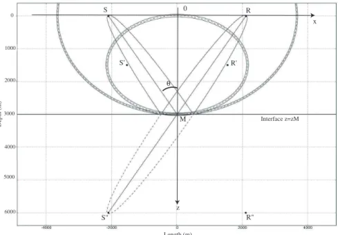
x z Interface z=zM 0 θ R" 0 1000 2000 3000 4000 5000 6000 Depth (m) Length (m) S R S' R' M S"
Figure 1: Representation, in the (~x,~z)-plane, of the Fresnel volumes involved in the wave reflection at the point M at a plane interface, under the incidence angle θ = 35◦. The source S and the receiver R are situated at a distance 3000 m from the interface. The image source is denoted by S”. The pair (S’,R’) can be viewed as image of (S,R) and would provide the same wave propagation as (S,R), but occuring entirely in the transmission medium. The velocities of the upper and lower media are respectively V1 = 2250m/s and V2 = 2800m/s,
and the frequency f = 25Hz. The seismic wavelengths in the upper and lower media are respectively λ1 = 90m and λ2= 112m. Incidence angle θ Transmission angle θ′ rk(m) r⊥(m) 1st term of D1 (m) 2nd term of D1 (m) 1st term of D2 (m) 2nd term of D2 (m) 35◦ 46◦ 418.4 343.5 27.5 0.04 40 0.3 50◦ 72◦ 600.2 387.7 35 0.12 93 52
Table 1: In-plane semi-axis rk and the transverse semi-axis r⊥of the Interface Fresnel Zone. Penetration distance D2 of the Fresnel volume beyond the interface, and thickness D1of the
region above the interface involved in the wave reflection, for two incidence angles θ and for the same configuration as in Figure 1.
6
a correction to the classical expression for the depth penetration of the FV across the interface in the lower medium, for subcritical angles and in the plane symmetry between the source and the receiver. The same method can be applied also out of the plane symmetry. Moreover, we have defined a region above the interface in the incidence medium which also contributes to the reflected wavefield. This constitutes a new important result for evaluating the effective reflectivity of a laterally heterogeneous reflector, and implicitly for evaluating the seismic resolution. Our work sheds new light in the open fundamental problem of the characterization of an interface from physical and seismic viewpoints.
REFERENCES
Cerveny, V., 2001, Seismic ray theory: Cambridge University Press.
Hagedoorn, J. G., 1954, A process of seismic reflection interpretation: Geophysical Prospect-ing, 2, 85–127.
Hubral, P. and T. Krey, 1980, Internal velocities from seismic reflection time measurements: SEG.
Knapp, R., 1991, Fresnel zones in the light of broadband data: Geophysics, 56, 354–359. Kravtsov, Y. and Y. Orlov, 1990, Geometrical optics of inhomogeneous media. Springer
Series on Wave Phenomena: Springer-Verlag, NY.
Kvasnicka, M. and V. Cerveny, 1996a, Analytical expressions for fresnel volumes and inter-face fresnel zones of seismic body waves. part 1: Direct and unconverted reflected waves: Stud. Geophys. Geod., 40, 136–155.
——– 1996b, Analytical expressions for fresnel volumes and interface fresnel zones of seismic body waves. part 2: Transmitted and converted waves. head waves: Stud. Geophys. Geod., 40, 381–397.
Lindsey, J., 1989, The fresnel zone ant its interpretative significance: The Leading Edge, 8, 33–39.