Development of a Pressurized Low-Temperature Tablet Press for a Carbon Dioxide Flash Frozen
Ice Confection
by MASSACHUSETTSOF TECHNO
David M.
Lopez
DEC
2 8
S.B. in Mechanical Engineering
Massachusetts Institute of Technology, 2007
Submitted to the Department of Mechanical Engineering
in Partial Fulfillment of the Requirements for the Degree of
Master of Science in Mechanical Engineering
at the
Massachusetts Institute of Technology
September 2009
©2009 Massachusetts Institute of Technology.
All rights reserved.
Signature of Author:
'
/ Department of Mechanical Engineering
August 1 9th, 2009
Certified by:
John G. Brisson II
Professor of Mechanical Engineering
Thesis Supervisor
AAccepted by:
David Hardt
Chairman, Department Committee on Graduate Students
INSTrIJTE LOGY
2009
IES
ARCHIVES
. -. KVDevelopment of a Pressurized Low-Temperature Tablet Press for a Carbon Dioxide Flash Frozen Ice
Confection
by
David M. Lopez
Submitted to the Department of Mechanical Engineering on August 19th
, 2009 in Partial Fulfillment of the Requirements for the Degree of Master of Science in
Mechanical Engineering
Abstract
This document details the conception, design, and testing of a series of prototype powder-pelletizing devices for use with an ice confection powder produced using a CO2 spray freezing process. The device
must function at a temperature of 233 K and at pressures of up to 12 bar(a) and must produce at least
500 pellets for use in consumer testing. Design considerations include stress analysis for critical parts,
minimization of powder flow path length, formulation of requirements of thermal management system, implementation of the powder compression methods, examination of various agitation methods, and the testing of the prototype apparatus. Trials proved the concept sound as several dozen pellets could be produced using the final prototype. However, ensuring sufficient powder flow for the consistent and continuous production of full-sized pellets is the key difficulty in the implementation of this device. As such, further work should be devoted toward understanding and quantifying the flow properties of the
CO2 flash freezing powder.
Thesis Supervisor: John G. Brisson II
Acknowledgements
I would like to thank Professor John G. Brisson and Professor Joseph L. Smith Jr. for providing me the opportunity to work on this project as well as for their generous assistance and guidance along the way. I would also like to thank Teresa Baker Peters for her explanations of the CO2 flash freezing process
and equipment as well as for acting as a sounding board for ideas along the way.
I would like to extend my gratitude to the entire staff of Nestle PTC Beauvais for being so extraordinarily welcoming and encouraging during my stay in France. I would especially like to recognize Anthony Pizzagalli, Maria Fernanda Villacis, Remi Thomas, Joumana Saikali, Hans Wille, Max Puaud, Robert Mazurek, Philippe Valour, Jean Judam, Francis Verdin, and Julien Minot for the help they provided and for all the time and effort they put in to this project.
Finally, I am extremely grateful for the support I received from my friends and family throughout this effort. I could not have done this without you.
Table of Contents
Abstract... ... ... ... 3
Acknow ledgem ents... 5
List of Figures ... 8
List of Tables ... 10
List of Sym bols ... ... ... 1... 11
List of Subscripts ... 12
Chapter 1: Introduction ... 14
1.1. Purpose ... 14
1.2. Constraints ... ... ... ... ... 15
1.2.1. Pressure and Tem perature ... ... 15
1.2.2. M aterial and G eom etry... ... 18
1.2.3. Product ... 19
1.2.4. Future Im plem entation ... 20
1.2.5. Sum m ary ... 20
Chapter 2: Initial Concept ... ... 22
2.1. Horizontal Loading Single Piston Com pression Device... ... 24
2.2. Horizontal Loading Dual Piston Com pression Device ... ... 27
2.3. Sum m ary ... 36
Chapter 3: Alpha Prototype ... 38
3.1. Description ... 38
3.2. Trials and Discussion ... ... 42
3.3. Sum m ary... ... 46
Chapter 4: Beta Prototype ... 48
4.1. Description ... 48
4.1.1. Core Com ponents ... ... 53
4.1.2. Side Com ponents ... 66
4.1.3. Therm al M anagem ent ... ... 98
4.2. Trials and Discussion ... 106
4.2.1. Initial Observations ... 106
4.2.2. Pellet Production... 110
4.2.4. CO2 Agitation Trials ... 116
4.3. Sum m ary ... 117
Chapter 5: Sum m ary and Future W ork ... 119
Chapter 6: References ... 122
List of Figures
Figure 1-1: Diagram of Ice Confection Production Equipment... ... 15
Figure 1-2: C02-H20 Phase Diagram ... 17
Figure 1-3: Drawings of the a.) Bottom and b.) Side Views of the Ice Confection Tank... 19
Figure 1-4: Gas-aided Ejection of a Shaped Pellet ... 20
Figure 2-1: Cross Sections of a.) a Vertical Compression Scheme; b.) a Horizontal Compression Scheme 23 Figure 2-2: Horizontal Loading Single Piston Compression Device, Conceptual Drawings ... 24
Figure 2-3: Top View of the Com pression W all ... 25
Figure 2-4: Rotating Compression Wall, Conceptual Drawings ... ... 26
Figure 2-5: Schem atic of Single Piston Device ... 27
Figure 2-6: Horizontal Loading Dual Piston Compression Device, Conceptual Drawings ... 27
Figure 2-7: Schem atic of Dual Piston Device ... 28
Figure 2-8: a.) Isometric and b.) Midline Cross-Sectional Views of the Proposed Sleeve ... 29
Figure 2-9: Horizontal Loading Sleeved Dual Piston Compression Device, Conceptual Drawings ... 30
Figure 2-10: Schematic of the Sleeved Dual Piston Device... 30
Figure 2-11: Originally Envisioned Agitation Options ... 31
Figure 2-12: Thermal Resistance Model for Convection and Radiation off of a Surface... 32
Figure 2-13: Cooling Circuit Plate Mounting Scheme ... 34
Figure 2-14: Exam ple Cooling Circuit Plate ... ... 34
Figure 2-15: Expansion Options for the Horizontal Loading Piston Compression Devices... 35
Figure 2-16: Module Stacking as a Method of Increasing Throughput ... ... 36
Figure 3-1: Alpha Prototype - Sleeved Dual Piston ... ... ... 38
Figure 3-2a. - d.: Alpha Prototype - Operation ... ... 40
Figure 3-3: A irlock Schem atic... 41
Figure 3-4: Mounting Schematic of the Alpha Prototype and Airlock ... 42
Figure 3-5: Seal Failure during a Trial on August 7th, 2008 ... 44
Figure 3-6: Seal Failure during a Trial on August 11, 2008 ... ... ... 44
Figure 3-7: Base of the Supporting Cart for the Alpha Prototype ... 46
Figure 4-1: Beta Prototype - Dual Piston, Front View... 49
Figure 4-2: Beta Prototype - Dual Piston, Exploded Front View ... 49
Figure 4-3: Product Flow Path... ... 51
Figure 4-4a, b, and c: Beta Prototype - Operation...52
Figure 4-5: Designed Upper Funnel Midplane Cross-Sectional View ... ... 53
Figure 4-6: Designed Upper Funnel, Angled Bottom View ... ... 54
Figure 4-7: Constructed Upper Funnel During Assembly, Bottom View ... 54
Figure 4-8: Comparison of Designed and Constructed Upper Funnels when Mounted. ... 55
Figure 4-9: Upper Funnel and Upper Funnel Anchor Plate - Top View... ... 55
Figure 4-10: Sketch from Above of a Funnel Made of Folded Delrin Sheet ... 56
Figure 4-11: View from Above of an Internal Funnel Made of Folded Delrin Sheet and the Filling Chamber ... 5 7 Figure 4-12: Drawing for a Planar Section of One-Half of the Folded Delrin Sheet Funnel... 58
Figure 4-13: Nestle Therm oform ed Inner Funnel ... 58
Figure 4-14: Cross Sectional View of the Lower Funnel... 59
Figure 4-15: Mechanical and CO2 Agitators, Front View ... 60
Figure 4-16: Initial Agitator Paddle ... ... 61
Figure 4-17a. and b.: Two Top Views of the Installed Mechanical Agitator Shaft and Paddle ... 61
Figure 4-18: Location and Sizing of the CO2 Agitation Ports on the Main Body ... 62
Figure 4-19: Upper Funnel Anchor Plate with O-Ring - Bottom View ... ... 63
Figure 4-20: Lower Funnel Anchor Plate - Bottom View ... 64
Figure 4-21: M ain Body - Profile View ... ... 64
Figure 4-22: Main Body - Labeled Cross-Section ... ... ... 65
Figure 4-23: Collection Container ... 66
Figure 4-24: The Pneum atic Actuators ... ... 67
Figure 4-25: Actuator Cross Section... 67
Figure 4-26: Actuator Flanges ... 70
Figure 4-27: Actuator Flange Cross Section, Small Actuator Side... ... 71
Figure 4-28: Pistons and Actuators ... 72
Figure 4-29: Cross Sectional View of Beta Prototype Showing the Pistons in the Loading Position... 73
Figure 4-30: a.) Small Piston and b.) Large Piston Stress Distributions, from COSMOSXpress... 75
Figure 4-31: Female vs. Male Piston Rod Thread ... 77
Figure 4-32: Therm al Isolation Tubes ... ... 78
Figure 4-33: Cross-Sectional View of the Thermal Isolation Tube ... ... 79
Figure 4-34: Temperature Profile along the Length of the Small Thermal Isolation Tube Given by Three Different M odels ... 84
Figure 4-35: From Top to Bottom- Top, Front, and Bottom Views of the Small Thermal Isolation Tube and Flange Assembly Showing Stress Distribution and Exaggerated Deformation ... 87
Figure 4-36: Side View of the Small Thermal Isolation Tube and Flange Assembly Showing Stress Distribution and Exaggerated Deform ation ... ... 87
Figure 4-37: S-N Curve for Stainless Steel... ... 89
Figure 4-38: Diagram for the Prediction of Fatigue Life ... .... ... 90
Figure 4-39: CO2 Flush Flanges... ... 90
Figure 4-40: Ideal CO2 Flush Circuit Diagram with Labeled Stations ... .... 91
Figure 4-41: Implemented CO2 Flush Circuit Diagram with Labeled Stations ... 92
Figure 4-42: Thermal Resistance Model for Heat Transfer between CO2 Flow in a Cylindrical Tube and the Am bient Environm ent... 96
Figure 4-43: Pressure Drop Through the CO2 Flush Line as a Function of Mass Flow ... 97
Figure 4-44: Picture of Coolant Loops Installed on the Beta Prototype in PTC Beauvais ... 99
Figure 4-45: Schematic of Cooling System as Installed in PTC Beauvais... ... 99
Figure 4-46: Flattened Flow-Path Schematic of Cooling System as Installed in PTC Beauvais ... 100
Figure 4-47: Thermal Resistance Model for Heat Transfer between an Insulated Apparatus and the Am bient Environm ent... ... 101
Figure 4-48: Container with Vent Line and Insulation ... 109
Figure 4-50: Ice Confection Tank of PTC Beauvais ... 112
Figure 4-51a and b: Mechanical Agitator Trial - Initial Paddle... 113
Figure 4-52: Mechanical Agitator Trial at MIT- Initial Paddle with Plastic Brush Bristles ... 114
Figure 4-53: Mechanical Agitator Trial in Beauvais - Asymmetric Partial-Rotation Paddle... 115
Figure 4-54: C02 Agitation Proof-of-Concept Test ... 116
List of Tables
Table 1: Actuator Specifications ... 69Table 2: Summary of the Results of Thermal Isolation Tube Heat Transfer Models ... 84
Table 3: Simple Stress Model - Input Values and Results ... ... 86
Table 4: Heat Transfer Rates due to Convection and Radiation ... 104
Table 5: Summary of Heat Sources ... 105
Table 6: Coolant Model Results for 2-propanol ... 106
List of Symbols
Symbol a d 6 E f Frit M' Id-ss V P P p S a T tV
x Meaning UnitCoefficient of Thermal Expansion I Thermal Diffusivity - I m2 s
-Diameter mm
Deflection mm
Young's Modulus Pa
Friction Factor
Critical Load for Buckling N
Gravitational Constant (9.81) m s2
Area Moment of Inertia m4
Length mm
Mass kg
Mass Flow kg s-1
Momentum Flux kg m s-2
Dynamic Viscosity Pa s
Coefficient of Friction between Delrin and Stainless Steel
Poisson's Ratio I Kinematic Viscosity - I m2 s
Pressure (absolute unless otherwise noted) bar
Density kg m-3
Stroke mm
Stress IStefan-Boltzmann Constant (5.67 x 10⁻⁸) Pa W m-2 K-4
Temperature K
Time I Thickness simm
Volumetric Flow m3 s-1
List of Subscripts
Note: Multiple subscripts can separated by a comma. Subscript a act air axial base bridge circ C02/CO2 COM comp ICT ID ins max OD pellet pr sat t-t t-t
be assigned to a single symbol. In these cases, the subscripts are
Meaning
Pertaining to Ambient Conditions Actuator
Pertaining to Air
In the Axial Direction
Pertaining to the Base of a Component Pertaining to the Location of Bridged Powder
In the Circumferential Direction Carbon Dioxide
Center of Mass Compression
Inner
Ice Confection Tank Inner Diameter Insulation Maximum Outer Outer Diameter Pellet
Piston Rod of the Actuator Saturation
Pertaining to a Tip Load Tip-to-Tip
total Total
tube Pertaining to a Tube, e.g. Thermal Isolation Tube
uniform Uniformly Experienced by a Part
w Pertaining to a Component Weight
Chapter 1: Introduction
This thesis describes a device designed to compress the powder created by the CO2 flash
freezing process into pellets for use in consumer testing. The compression process is to occur as powder is being formed, with the goal of having a continuous process producing homogenous product. This first chapter provides background information on the CO2 flash freezing process and on the goals of this
specific part of the project. Chapter 2 presents the initial concept of this form of pelletizing machinery. In Chapter 3, details of the alpha prototype are discussed, including its form, trial results, and
conclusions drawn from this device. Chapter 4 is about the beta prototype, touching on its design, trial results, and conclusions. Chapter 5 summarizes the conclusions reached in Chapter 4 and presents the most relevant aspects of the C02 flash freezing process that should be focused on in further work.
1.1.Purpose
The Nestl6/MIT CO2 Flash Freezing collaboration is meant to produce an ice confection that
fizzes as it is consumed. The production process creates very fine, snow-like powder, which can then be compressed into a pellet for consumption. A diagram of the current production equipment is shown in Figure 1-1, which will be a useful reference during the following description of the process. Liquid mix is injected through a pressure swirl nozzle into liquid CO2 in the Emulsion Chamber. This chamber typically
experiences temperatures between 283 K and 293 K (10"C to 20°C) and has a chamber pressure of approximately 50 bar. This liquid emulsion is then sprayed through a pressure-swirl nozzle, atomizing the mixture as it enters the Ice Confection Tank (ICT). The ICT is held at a pressure of approximately 10 bar, which is low enough to cause the liquid CO in the mixture to vaporize. Liquid carbon dioxide vaporizes, lowering the temperature of the ICT and the mix to boiling point temperature of the C02,
equal to 233 K at the tank's 10 bar pressure. At this combination of pressure and temperature, the water and CO2 form a phase called a carbon dioxide clathrate hydrate, in which molecules of CO2 gas are
trapped within cages of water molecules. The release of the CO2 from these structures upon
consumption is what gives the product its characteristic fizziness.
Development of the CO2 flash freezing process has been ongoing since 2006. To further develop
this product, between 250 and 500 pellets are required for a consumer testing panel. Individual pellets have made by manually compressing powder in a piston-cylinder apparatus held in a freezer or cold room. Unfortunately, this method results in large pellet-to-pellet and batch-to-batch variations in key product characteristics, such as CO2 concentration, texture, and density.
The goal of this project is to develop a continuous production method of pellets that will substantially reduce the variability of the product and allow the rapid production of the required number of pellets. Continuous production should result in a homogeneous product by limiting the effect of transients during initial powder production. The device must produce at least 500 homogenous pellets while working with the existing equipment. In addition to the requirements
Liquid Mix
Pressure Swirl Nozzle for mix
Liquid CO2
Emulsion Chamber 50 bar, 283 -293 K
Pressure Swirl Nozzle
for COJmix emulsion
Ice Confection Tank (ICT) --10 bar, 233 K
Powder
Outlet
Figure 1-1: Diagram of Ice Confection Production Equipment
focused on the production of pellets for the consumer trials, the design should include plans for scaling up the device to match its throughput to that of a large production line.
Since the packaging for this product has not yet been finalized, the production device will be designed to deliver pellets to the operator so that they can be manually inserted into their containers. Thus, the device must serve as both a compressor and extractor. Compression refers to the formation of the pellet through forcible compaction of the powder. Extraction refers to the removal of the product, either powder or pellets, from the high pressure environment of the production equipment. The extraction operation could occur before or after that of compression; the order of operation choice is described in Chapter 2.
1.2.Constraints
The design of an extraction and compression device for use with the CO2 Spray Freezing product
is subject to several constraints. In the following sections, the most important of these constraints will be described.
1.2.1. Pressure and Temperature
Two of the most important constraints are the operating pressure and temperature of the production equipment. Any extraction device will need to withstand both the high pressures and low temperatures required to produce desired characteristics of this product. The CO2 spray frozen ice
confection relies on the cooling effects of flashing carbon dioxide to freeze the liquid mix and maintain the temperature in the Ice Confection Tank, so production must occur at a pressure and temperature combination at which CO2 can exist as a gas. Its fizziness, however, is dependent on the presence of
clathrate hydrates in the powder produced, so conditions must also be amenable for the presence of this phase. Examination of the C02-H20 mixture phase diagram, presented in Figure 1-2, provides
guidelines for the pressure and temperature requirements of the process.
Both CO2 and H20 exist in their usual solid, liquid, and gaseous forms at various points on the
phase diagram. However, they can also combine to form the carbon dioxide clathrate hydrate phase at certain pressures and temperatures. The region in which this phase exists is shaded in blue in Figure 1-2. The lower boundary of the CO2 clathrate hydrate region is the water hydrate-ice line, which runs
from the point labeled {LW} in the lower left of the diagram through the points labeled {SL}, and {SI} in the upper right of the graph. Directly above the hydrate-ice line and to the left of the triple point of CO2
(217 K, 5.3 bar) is carbon dioxide's liquid-vapor line. This line defines the relationship between pressure and the temperature at which liquid CO2 boils. It also defines the operating temperature of the Ice
Confection Tank. The tank's pressure is regulated to a constant value and enough excess liquid CO2 is
vaporized during production to pull the temperature down to its liquid-vapor equilibrium value. The CO2 liquid-vapor line is well within the clathrate hydrate region of the phase diagram, thus ensuring the
formation of clathrate hydrates within the product.
As mentioned above, the process relies on the evaporation of liquid CO2 to cool the chamber.
Current production methods call for a flow of CO2three to four times that of the mix, far greater than
the 0.2 to 0.3 ratio required to provide sufficient CO2to stabilize the clathrates in the powder (Pizzagalli, 2008, Guide d'utilisation...). As a result, the extra CO2 provides the required cooling effect to stabilize
the temperature of the ice Confection Tank at the value on the CO2 liquid-vapor line for the selected
pressure. Thus, the operating pressure of the system determines its temperature. Transient conditions can arise where the operating pressure does not determine its temperature, most notably during the very start of powder production and after sudden perturbations to either pressure or temperature.
Higher pressures, and thus higher temperatures, allow for greater operating efficiency of the equipment and also assist in the formation of clathrates (Baker, 2006). Therefore, it is desirable to run at the highest pressure that can be obtained. However, from an equipment design point of view, low temperatures are easier to design for than high pressures. It was decided that the process would run between 10 bar and 11 bar as a compromise between efficiency and simplicity of design, corresponding to temperatures of 238 K (-350C) and 233 K (-40°C) on the liquid-vapor
CO2 line. In Figure 1-2, the thick,
horizontal dotted line marks the range between 10 and 11 bar pressure, and the vertical dotted lines denote 238 K (-35"C) and 233 K (-40*C). The red rectangle in Figure 1-2 shows the approximate operating range of the process. The extremes of this operating range provide the design pressures and
temperatures of the device.
There is a possibility of running the compression and extraction device slightly warmer than the conditions inside of the tank if the above design temperature cannot be easily achieved. According to a compilation of data done by Baker from literature on clathrate hydrate formation, the equation for the H20 hydrate-ice line, shown as the bottom border of the clathrate hydrate region of Figure 1-2, is given
by (Baker, 2009):
In(P) = 0.0432 T - 9.3826 (1)
100 IOWOf 0! 1001 104
O'1
001 . L M .. 1 $s -HwctailratcI c(Mhnftc Gei .. u...uu.ice
gas
o'
(I 7)SLW
CE-P C E Pt)
Vlvter J~
So oTK
Figure 1-2: CO2-H20 Phase Diagram
Adapted from Longhi, 2005. The horizontal dotted line denotes the operating pressure of the COz spray freezing equipment, while the vertical dotted lines show the maximum and minimum operating temperatures of this equipment. The intersection
of these ranges is shown by the red rectangle.
In Equation (1), P is in units of bar and T is in units of Kelvin. According to this relation, at the 10 bar
design pressure the maximum temperature for clathrate stability is 270 K (-3"C). Any powder- handling device could theoretically be run at this temperature without much degradation of the product. In order to ensure that the powder is never exposed to elevated temperatures, however, the more conservative design temperature limit of 253 K (-20*C) is assumed, providing a larger margin for localized heating effects and other temperature perturbations.
These devices will have to occasionally deal with even more extreme conditions, especially regarding temperature. During the venting process, when the pressure of the tank is returned from its operating value to ambient, temperatures often fall to approximately 213 K (-60C). Though this venting process will be a rare occurrence during a continuously operating production run, care was taken to ensure that the new device was designed so as to not incur any damage when exposed to temperatures at these levels.
.. . . ... ... ..
1.2.2. Material and Geometry
Closely related to the constraints of pressure and temperature is that of material used in the construction of the device. The production tank is made of AISI Type 316L (1-4404) stainless steel, which has a coefficient of thermal expansion of roughly 16.0 lim/(m*K) (AK Steel). In order to ensure that the extractor is compatible with the tank at all temperatures so as to form a good seal to hold the operating pressure constant, the coefficient of thermal expansion of the material used to construct the new apparatus should approximate this value. The fatigue properties of the material must also allow the extractor to undergo many cycles from atmospheric pressure to operating pressure and back again while allowing the geometry of the design to remain reasonable. Finally, the material must be approved for usage with food.
The surface finish of the selected material is also of critical importance. It was experimentally shown that the powder is very likely to stick to bare stainless steel, especially during and after pellet compression. This tendency was most pronounced for temperatures above 233 K (-400C). This makes
surface finish an important factor in the design of compression and extraction equipment, where temperatures will likely be slightly higher than they are in the production tank.
Experiments carried out at 253 K (-20"C) showed the powder to have a strong tendency to stick to stainless steel at this temperature even when loose. When compressed, the product adhered to the stainless steel strongly enough to resist a dislodging pressure of 15 bar on a compressed
16-mm-diameter by 20-mm-length cylindrical pellet stuck in the compression cylinder. The pellet also stuck to a stainless steel piston face with enough tenacity that removal resulted in the separation of a layer of compressed powder from the pellet's face, which remained firmly attached to the piston. This
separation left the end of the pellet rough and unevenly textured. This is less desirable to the consumer than the smooth, flat surface finish left after a successful ejection, and thus is unacceptable from a marketing point of view.
Fortunately, this penchant for sticking was nearly eliminated through the use of non-stick coatings, such as Accoat's Accolan Silver fluoroplastic coating (the properties of which are described in detail in the technical data sheet for Accolan Silver by Accoat A/S), or by the utilization of low-friction plastics in these critical areas. Powder compression in a plastic sleeve or with a plastic piston, in contrast, does not result in jamming or sticking. Care was taken to ensure that the thermal contraction of adjacent parts made of these differing materials did not cause any interference.
In order to meet the goal of continuous production, the pellet forming device must collect the powder produced in the Ice Confection Tank as it is being produced. The easiest way to enable this collection is to attach the device to the bottom of the ICT. As shown in Figure 1-3, the bottom of this tank is a hinged door with an inner diameter of 300 mm, and at the center of this door is a 150 mm inner diameter outlet port with a standard 150 mm quick clamp fitting at its end. During operation, the hinged door is held in place by eight clamps arranged around the circumference of the device. A device could be constructed so that it either attaches to the 150 mm quick clamp fitting or replaces the
4-- Emulsion Chamber
attaches to the top
0
0
---Clamps 150 mm quick
a. b. clamp fitting
Figure 1-3: Drawings of the a.) Bottom and b.) Side Views of the Ice Confection Tank
In both figures, the hinged door of the tank and everything attached to it are shaded gray for clarity. Adapted from a drawing provided by ERI-EST (Guichard).
hinged door entirely. Replacing the hinged door would require recertification of the Ice Confection Tank
(ICT) with the device attached in order to bring it into compliance with French law regarding
pressure-holding vessels, so initial prototypes were constructed to take advantage of the standardized fitting at the bottom of the ICT.
1.2.3. Product
The final category of design constraints deals with the finished product itself. The product is meant to be a fizzy ice cream, so it is important that the powder does not lose its fizziness before it is compacted into a pellet and packaged. Experimental data have shown that CO2 clathrate hydrates have
a dissociation time constant of 24 minutes in fresh powder at atmospheric pressure and 253 K (-20"C) (Pizzagalli, 2008). Thus, it is imperative that the time the powder is exposed to atmospheric pressure, especially at higher temperatures, does not exceed more than a few minutes. As a consequence, a time of one minute has been chosen as the maximum time that the powder should be allowed to remain at atmospheric pressure.
Product size and shape is another key element of device design. It was initially decided that the final product be a cylindrical pellet measuring 18 mm in diameter and 10 mm in height. This pellet is to
be formed by compressing loose powder into a volume roughly one-fifth its initial size, giving a compression ratio of five-to-one. It was experimentally determined that the pressure required on the flat face of a pellet to achieve this level of compression is approximately 15 bar.
Compressed gas
Figure 1-4: Gas-aided Ejection of a Shaped Pellet
Physical appearance of the pellet is also an important parameter. Although the initial
requirements call for a cylindrical pellet, more attractive pellet forms are currently under consideration. The most popular of these alternative forms are spherical or oblate spheroid shapes (such as Mars' M&Ms or Nestle's Smarties), which require that special attention be paid to the surface finish of the compression molds so as to avoid sticking and entrapment after the compression process. Experiments have also shown that an ejection mechanism is also needed for hemispherical molds regardless of the surface finish; compressed gas injected through a hole in the mold behind the pellet, as depicted in Figure 1-4, has shown promise in dislodging a stuck, spherically formed piece. It is important that the design of the pellet forming device considers possible moves from a cylindrical pellet to a spherical or oblate spheroid geometries.
1.2.4. Future Implementation
Any device designed should also take the future expansion of the production line into consideration. Current estimations put production rate at five to ten million 100 mL packages output per year at roughly 20 g of product per package, creating a need for approximately 100 to 200 million grams of powder a year. The current production rate of approximately 1.2 g/sec results in a total yearly production rate of 20.4 million grams of powder, if the device is operating for 54% of the 8760 hours in a year. Thus, the production rate of this process will have to be expanded to roughly five to ten times its current value in order to supply the necessary amount of powder. If a machine has its compression and extraction capabilities strained to simply keep up with the current production rate, then it will require much more time, effort, and money to adapt to the increased flow of a final production line. It is desirable, then, that any device created has excess extraction capacity or has the ability to be easily modified to add additional capacity.
1.2.5. Summary
In summary, a device meant to interact with and/or extract the powder from its production tank must be able to withstand an operating pressure and temperature of 11 bar and 233 K (-400C),
respectively. Any prototype equipment produced should be compatible the 150 mm diameter clamp fitting on the outlet port of the tank for ease of installation and maintenance. It should be made of
stainless steel to meet sanitary guidelines for food equipment. Every valve, seal, coating, and material used in any device that contacts the product needs to be approved for use with food, further supporting the use of stainless steel. The temperatures of the powder and pellets should never rise above 253 K (-200C), and the time that it remains at atmospheric pressure should be limited to one minute or less.
The purpose of the device is to produce 250 to 500 homogenous pellets for consumer trials. This machine should be able to form cylindrical pellets with a diameter of approximately 18 mm, a height of approximately 10 mm, while utilizing a compression ratio of 5:1. Attaining this level of compression was found to require a pressure of approximately 15 bar, so the compressor should be capable of providing at least this amount of force. The apparatus should be designed with some degree of shape flexibility for the pellet. While cylindrical pellets are acceptable, 18 mm diameter spherical pellets are preferred, and other shapes may also be suggested in the future. A full-scale production line will also feature a maximum production rate of approximately ten times that of the current prototype, so the throughput of the compression and extraction mechanisms should be easily expanded to handle this increase.
Chapter 2: Initial Concept
The first design choice made was that of the working order of the compression and extraction device. As explained in Chapter 1, the device must function as both a compressor and an extractor. The order in which these processes occur can be set by the designer. Initial ideas mirrored the current batch process, in which the powder is extracted from the tank and then manually compressed at atmospheric pressure. This extraction-compression method has been generally successful when utilized with the manual batch process, but it does have some drawbacks. During depressurization of the Ice Confection Tank, a large piece of dry ice can form at the bottom of the tank. This mass of dry ice, formed once every few trials, clogs the outlet of this tank and prevents powder flow when the tank is opened. During a production run with a pellet forming device in place, the formation of this chunk of dry ice during a depressurization cycle would require the cessation of the trial until it is removed from the system. This is not only time consuming, but also prevents continuous production.
Another problem with the extraction-compression method is the behavior of the powder under atmospheric pressure. The powder tends to sinter and clump once at atmospheric pressure, making it more difficult to load into the piston-cylinder apparatus used for compression. During manual
compression, the powder is stirred as it is loaded into the compression cylinder and large, sintered chunks are discarded. This problem not only results in excessive waste in the form of the rejected chunks of powder, but it also requires there to be a reliable method in sorting these chunks from the powder so that they do not clog the compression cylinder.
A method in which the powder is compressed while under pressure and then the pellets are
extracted from the pressurized environment was also examined. With the compression-extraction method, the powder is maintained at the ICT pressure and temperature. It is hoped that this will prevent excessive dry ice formation as well as the flow issues caused by powder sintering and clumping.
The pellets are also much less sensitive to the temperature and pressure changes experienced during depressurization due to their greater density, cohesiveness, and lower surface to volume ratio when compared to the loose powder. The much greater density of pellets compared to powder also means that fewer depressurization cycles will be required for the production of a given number of pellets, decreasing the likelihood of dry ice formation occurring and disrupting a trial and limiting the effects of pressure fluctuations due to depressurization on the process itself.
The compression-extraction method does have its own limitations, however. Several powder agitation and compression components move to perform their functions. This means that the
pressurized volume of the device must either be large enough to contain these parts and their actuators, increasing the size and weight of the machine, or dynamic seals must be found that can withstand the operating conditions of the device. Observation of powder flow and pellet formation, both of which occur under pressure, will also be greatly inhibited by the pressure-holding walls of the device. This will make it more difficult to troubleshoot any issues the device may have, since it will be very difficult to determine where, when, and how any problems crop up.
Ice Confection Tank Ice Confection Tank
Settled Powder *--Compression
Settled Powder I Chamber
Bridged Powder
Empty Space , ,-- Compression Chamber
a. b.
Figure 2-1: Cross Sections of a.) a Vertical Compression Scheme; b.) a Horizontal Compression Scheme The compression chambers are encircled by dashed-line rectangles for clarity.
After careful consideration of the two methods, it was decided that the compression-extraction method was the better of the two options. Experience with dry ice formation and powder behavior seen with the current batch production method suggests that powder flow will be a troublesome issue with the extraction-compression method. The compression-extraction method does not expose powder to changes in temperature or pressure until after it has been compressed into a pellet, at which point it is much less sensitive to these variations. It also limits the number of depressurizations required for the production of a set number of pellets, avoiding possible complications caused by either dry ice
formation or pressure fluctuations.
Several prototype pellet formation devices based on the compression-extraction mode of operation were examined during the initial stages of this project. In all of these devices, powder flowed vertically down a cylindrical tube into a compression chamber as shown in Figure 2-la, where it was then compressed into a pellet. All such devices were found to experience severe problems with powder flow during the loading processes. Specifically, the powder would flow a short distance down the cylinders and then bridge, blocking the passage and preventing powder from filling these volumes to create pellets of the desired size and texture. Attempts to experimentally quantify this distance-to-bridging were foiled by the sintering and clumping behavior of the powder as described above. Coating the walls of the cylindrical passageways with a Teflon-like coating had a beneficial effect on powder flow, especially when the powder was being manually agitated, but it did not solve these issues.
In an attempt to alleviate the bridging problem, powder flow path geometry was reexamined. Rather than having powder flow down a long, thin vertical compression chamber, it made more sense to have powder flow down through the side of a horizontal tube, as shown in Figure 2-1b. This decreases the distance the powder has to flow, thus increasing the chance that it completely fills the chamber. Though a horizontal compression layout should be advantageous regarding powder flow, it is not without drawbacks. Pellet ejection is no longer assisted by gravity, which may make it more difficult to
dislodge pellets that stick to the compression surfaces without the use of additional ejection mechanisms. The device will also be longer than a machine with a vertical layout, which means that care must be taken to ensure that the designed equipment will fit underneath the existing production apparatus.
2.1. Horizontal Loading Single Piston Compression Device
The initial concept of a horizontal loading compression device was one in which a piston compressed powder against a movable wall. See Figure 2-2 below for a pictorial description of its actuation cycle. These actions take place subjected to tank pressure, 10-12 bar, and under temperatures ranging from 233 K to 243 K (-40"C to-30C).
The cycle starts with the filling step, in which the piston is held retracted as powder drifts down from the ICT and collects in front of the piston in the filling chamber. Once this filling chamber is full, the piston moves to the right, pushing the powder to the right and compacting it against the wall at the end of the compartment. The wall descends for the final ejection step, thus allowing the piston to continue its forward motion and push the pellet out of the compression chamber so it can fall to the
Ice Confection Tank Ice Confection Tank
Pellet
To Actuator
Filling Chamber Compression Wall
Compression Chamber ToActuator
To Actuator
Ice Confection Tank
Pellet
Outlet Port
Figure 2-2: Horizontal Loading Single Piston Compression Device, Conceptual Drawings
Clockwise from Upper Left: Filling, Compression, Ejection. An airlock is attached below, its location denoted by the arrow. The
dotted square in the first figure highlights the portion of the device seen from above in Figure 2-3.
Compression Chamber
Rod to Actuator ) Support Tracks
Compression
Wall--Figure 2-3: Top View of the Compression Wall
Shows the supporting track the wall rides in, providing support during compression events.
airlock below. In order to avoid excess wear at the wall-track interface, the force exerted by the piston's actuator may need to be decreased while the wall is moved.
The compression wall is an integral part of this concept and presents a few design challenges. It must be stiff enough to withstand the force of the piston as it compresses the powder, and must also be able to move vertically to allow for the ejection of a pellet. One way in which this could be assured is to have the wall move in a track that constrains it in the horizontal direction, as shown in Figure 2-3.
This track has several constraints placed upon it. It must be strong enough that it does not deform under load, and it must be made of a food-grade material. There must also be little friction between the compression wall and its track so that the wall can be easily retracted after the pellet is formed without damaging the wall, the track, or the pellet. Stainless steel coated with a low friction material, such as Teflon, would likely be satisfactory, as would several kinds of structural polymers such as Delrin. Since the track will be constructed of or coated with a low-friction material, it is expected that any powder trapped in the track will be easily dislodged by the motion of the wall and will not threaten to jam the equipment.
A sliding wall limits the shape of a pellet to something with a flat side, as forming this wall into
some other shape would make it extraordinarily difficult to prevent pellet damage as it is retracted. If the pellet sticks to the wall-mold as the wall is pulled downwards by its actuator, it will be damaged due to the constraints imposed by the walls of the compression chamber, which will not allow the newly
formed pellet to follow the wall on its downward journey. In order to allow for more flexibility in product shape, a rotating wall was proposed, as shown in Figure 2-4.
The actuation cycle remains the same, with the only difference being that the wall now rotates out of place rather than sliding out of place. This rotation is achieved through the combination of a
hinge at the top of the wall and an actuating mechanism that can drive rotational movement. The wall's rotation should break the pellet loose if it becomes stuck to the wall during compression. If the pellet becomes stuck to the piston, it can be successfully ejected through use of an ejection mechanism on the wall itself that pushes the pellet downwards when the piston is fully extended.
Ice Confection Tank
To Actuator
1
Pressurized gas line
Pelle\
Ice Confection Tank
Wall rotates to allow
pellet ejection
utlet Po
Figure 2-4: Rotating Compression Wall, Conceptual Drawings
Clockwise from Upper Left: Filling, Compression, Ejection. Pressurized gas ejection mechanism shown. The outlet is denoted by a downwards-pointing arrow.
Two possible ejection mechanisms were considered for this concept. One was mechanical, consisting of a piston located in the center of the wall that could be actuated after the wall has rotated. The other was a stream of pressurized CO2 gas as it is already available in the system and will not
contaminate the product with other materials. This stream would be directed at the top of the pellet, dislodging it from the piston and pushing it downwards out the outlet port.
The hinge, however, has a few questions associated with it. It is unknown how a hinge will hold up to the high pressures and low temperatures found in the tank, especially if abrasive dry ice is formed during the process. An actuator must be found that can rapidly open and close the rotating wall and be strong enough to hold the wall shut during the compression process. If the wall is to hold against tank pressure, the actuator will need to be strong enough to provide adequate sealing force and withstand the combination of the pressure and compression forces. Regardless of the actuation method of the compression wall, the core of the horizontal loading single piston compression device will look the same.
In Figure 2-5, a rough schematic of such a machine is shown, giving a feel for the size and layout of this sort of apparatus.
*5:1 compression ratio *Final pellet size: 10 mm *Need 50 mm of powder Edge of Compression Chamber Curved Bottom of Collection Zone Sect. A-A To Actuator / / / / / Compression Piston 110mm A
Powder Collection Zone
Compressi
Compression Chamber
- ' /. -I
50 mm 50 mm
Figure 2-5: Schematic of Single Piston Device
2.2.Horizontal Loading Dual Piston Compression Device
Another concept of a horizontal loading compression device was called the dual piston compression device. In this machine, one piston compresses the product against the surface of a second piston, which can then move to allow for ejection. Figure 2-6 below depicts this actuation cycle. As with the single piston design, these actions take place under tank conditions, corresponding to pressures between 10 and 12 bar, and under temperatures of 233 K (-400C) to 243 K (-300C).
Ice Confection Tank
Filling Chamber
Ice Confection Tank
Compression Chamber
Pellet
Ice Confection Tank
To Actuator Pellet--7'l1
Figure 2-6: Horizontal Loading Dual Piston Compression Device, Conceptual Drawings
Left to Right, Top to Bottom: Filling, Compression, Ejection. A Pressurized Gas Ejection Mechanism is depicted in this figure.
ion Wall
E
p
To Actuator Outlet PortI
r
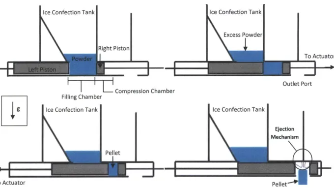
The cycle starts with the piston retracted as powder flows down from the Ice Confection Tank and collects in the filling chamber. After the filling chamber is full, both the left and right pistons move to the right, pushing the powder into the compression chamber and separating it from the powder
remaining in the ICT. Once all of the powder in that load is in the compression chamber, the right piston stops and the left piston continues its forward motion, compacting the powder against the front surface of the stationary right piston. The right piston then moves to the right, allowing the left piston to continue its forward motion and push the pellet over the outlet port on the bottom of the device, where it falls to an airlock below. Should the pellet stick to one of the piston faces, an ejection mechanism, such as an additional piston or a blast of pressurized CO2 gas, can be located above this outlet port to
push or agitate the pellet to assist it in exiting of the compression device.
This dual piston layout could also act as an airlock between the Ice Confection Tank and an unpressurized outlet port through the use of ring seals on the pistons themselves, which would preclude the use of a separate airlock to perform this function. The pellets would still be created under pressure,
but when the right piston moves past the outlet port during the ejection step the pellet would be depressurized. This method of sealing would require careful synchronization of the two pistons to ensure that there is never an open gas path from the tank to the outside environment, but could reduce the overall complexity of the powder processing equipment. These seals must be able to deal with the
dynamic motion of the pistons, the high pressures and low temperatures of the ICT, and the possible presence of abrasive dry ice without losing their effectiveness.
As with the single piston compression machine, a schematic showing the layout of the device and giving estimated dimensions is shown in Figure 2-7. The estimated length of the dual piston apparatus is 260 mm, slightly greater than the 210 mm of the single piston machine. The locations of the right pistons are labeled 1, 2, and 3, with 1 being its location during the filling step, 2 its location during pellet compression, and 3 its location during ejection.
*5:1 compression ratioEdge f Compression
Edge of Compression
-Final pellet size: 10 mm Chamber
-Need 50 mm of powder Curved Bottom
of Collection Zone Sect. A-A Ejection Mechanism ToActuator / A
LeftPiston Filling Chamber 1..p... 2 . 3
SChamber Exit
120 mm A 50 mm 50 mm 10 20 mm 10
mFigure mm
Figure 2-7: Schematic of Dual Piston Device
i- Filling Slot
50 mm 50 mm
18 mm
Left Pisto Filling Chamber Compression Chamber
a. Cylinder b.
Figure 2-8: a.) Isometric and b.) Midline Cross-Sectional Views of the Proposed Sleeve
The dual piston apparatus has several inherent advantages over the single piston concept. In a dual piston machine, all motion and actuator-induced forces are along the axis of the loading and compression chambers, which greatly reduces the friction load and potential for wear of these parts when compared to a sliding wall setup. A dual piston compressor also has fewer independent critical features than a single piston and wall apparatus. With a piston and wall setup, two separate problems need to be solved - that of moving and sealing a piston, and that of moving and sealing a wall. With the dual piston setup, only one of these problems needs to be addressed in order to produce a functional device.
The dual piston design does have a few problems, however. The largest one of these is its requirement that the right piston have three set positions, as shown in Figure 2-6 and Figure 2-7. Though this is easily handled with the implementation of a mechanical piston actuation system, the planned use of readily-available pneumatic actuators required the addition of a mechanical stop, which raised safety concerns. The device is also longer than the single piston design, which makes it slightly harder to handle during mounting, dismounting, and device transportation situations.
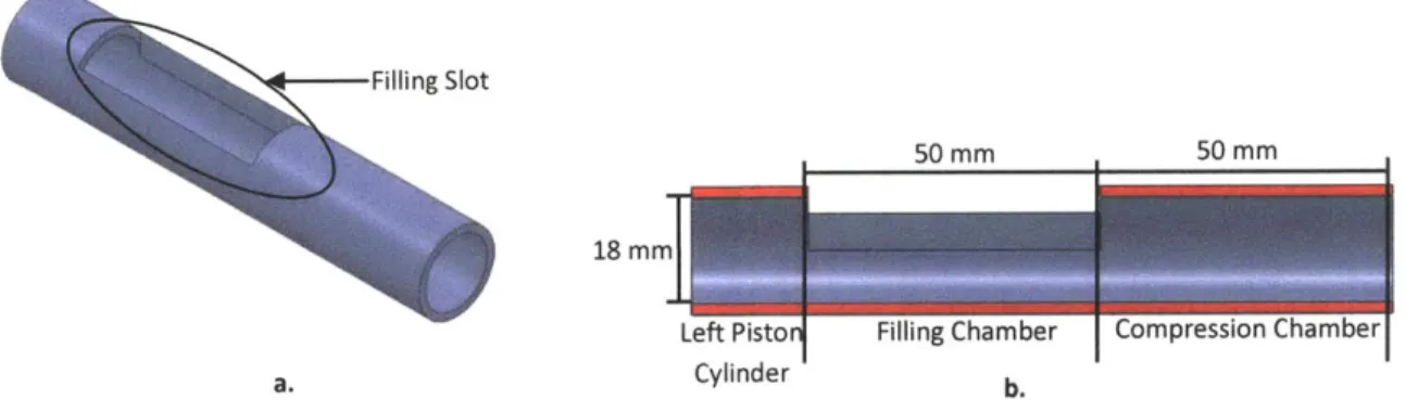
Another option for the dual piston concept would obviate the need for a separate compression chamber, thus eliminating the intermediate position of the right piston and alleviating the subsequent safety concerns. Rather than pushing the powder into the smooth compression chamber, the chamber can be formed around the powder through the use of a mobile cylindrical sleeve. This sleeve has a filling slot cut through its upper surface to allow the filling chamber to be open to the Ice Confection Tank above. The sleeve slides over to enclose the powder that fell into it during the filling process, at which point compression and ejection are carried out as before. An isometric and a cross-sectional view of a model sleeve are shown Figure 2-8. It should be noted that this model does not include any
considerations of the attachment of an actuator needed to move the sleeve back and forth. It simply illustrates the concept in a clear way.
Figure 2-9 shows the actuation cycle of this proposed device. In order to keep the drawing neat and clear, the sleeve has been represented schematically as a series of lines corresponding to cross-section view shown in Figure 2-8b.
Ice Confection Tank
Sleeve (in red)
Ice Confection Tank
Right Piston
Ice Confection Tank
Ejection Mechanism: Piston or Pressurized
Gas Line
Itlet Port
Pellet Pellet'
Figure 2-9: Horizontal Loading Sleeved Dual Piston Compression Device, Conceptual Drawings
Left-to-right, starting on top: Filling, Sequestration, Compression, Ejection. The sleeve is colored red for clarity. Note that the sleeve slides over during the sequestration step to fully enclose the powder. A Pressurized Gas Ejection Mechanism is depicted
in this figure.
This cycle begins with powder falling from the Ice Confection Tank above through the hole cut into the upper surface of the sleeve and into the filling chamber. Once this chamber is full, the sleeve is pushed to the side, sliding its upper hole away from the filling chamber and thus sequestering that
*5:1 compression ratio -Final pellet size: 10 mm -Need 50 mm of powder To Actuator I _ _ ; / Edge of Compression Chamber 4 - Curved Bottom of Collection Zone Sect. A-A -- Ejection Mechanism Right Piston Final Position To Actuator
Figure 2-10: Schematic of the Sleeved Dual Piston Device
The sleeve is colored red for clarity and is shown in the loading position in this diagram. To Actuator
,
Wom,
I Rotating Paddle Vibrator
Sleeve
Figure 2-11: Originally Envisioned Agitation Options
powder from both the ICT and the outlet of the device. The left piston then moves to the right, compressing the powder against the stationary face of the right piston and forming a pellet. The right piston moves to the right to eject the pellet, allowing the left piston to extend further and push the pellet out of the sleeve. The pellet then falls through the outlet of the machine and into the airlock waiting below. Also as before, an ejection mechanism can be located above this outlet port to push or
agitate the pellet to assist it in exiting of the compression device should the pellet stick to the face of one of the pistons. A simple schematic of the concept is presented in Figure 2-10.
This layout allows for the elimination of the separate compression chamber of the previous designs. This eliminates the length of the compression chamber and the length and stroke of both pistons, since neither piston needs to traverse a separate compression chamber. This limits device length to approximately 170 mm, compared to the 260 mm of the dual piston concept and the 210 mm
of the single piston one. The advantages of this design do come at a price, however. The powder flow path length is increased marginally, which could make the device more prone to bridging. The design of the concept is also more complicated with the addition of the sleeve, the extra actuators required to
move this part, and the additional seals required by the presence of the new part. Given its advantages, the more complex design of the sleeved dual piston is acceptable, and the slight increase in powder flow
path is not expected to be problematic. Thus, it was chosen as the one to pursue further.
There are several additional issues that must be considered in order to more fully evaluate the potential of such a design. The most important of these issues are powder agitation, equipment cooling, and consideration for future expansion to a full-scale industrial line. In Figure 2-11, two different
methods of agitating the powder to keep it flowing into the pellet forming device are displayed. The first of these is an industrial vibrator, which could be strapped to the exterior of the Ice Confection Tank or the pellet forming device. It would constantly shake the entirety of the apparatus to prevent the
powder from settling down and sticking to the walls of the equipment or to itself. Another option is a mechanical paddle, operated by a shaft passing through a hole in the wall of the funneling section directly above the powder collection zone. This paddle wheel would continually rotate during the production process, stirring the powder and keeping it from bridging over the entrance to the pellet
forming device's filling chamber. One or both of these methods of agitation could be implemented if necessary.
The temperature of the pellet forming device should be held between temperatures of 233 K
(-40*C) and 253 K (-20*C). Experience has shown that the powder tends to sinter and bridge more effectively with increasing temperatures, so the device must be kept below 253 K. If the temperature of the apparatus is too low, the CO2 gas in the device can liquefy (233 K) or even solidify (218 K),
compromising the quality of the product and possibly preventing the production of pellets.
Thermal Resistance due to Convection:
1 = hcon A
s"r Thermal Resistance due Tair to Radiation:
1
Rrad = 4 E T A
Figure 2-12: Thermal Resistance Model for Convection and Radiation off of a Surface
A simple model can be used in order to obtain an estimate of the cooling load placed on this
system. The heat load placed on this device will be due to natural convection and radiation. Since the device temperature will be close to that of its environment, the thermal resistance model will be valid for both of these modes of heat transfer. In the equations given below, hcon is the convective heat transfer coefficient, A is the external area of the device, E is the emissivity of the device, a is the Stefan-Boltzmann constant (5.67 x 10⁻⁸ W m-2
K-4), and T, is the average temperature of the surface of the device (Ts,,f) and the air (Tir).
= (Rcn + Rr 1 ) (Tsurf - Tair) (2)
Several assumptions have been made in order to use Equation (2) to determine the rate of heat flow into the device. It is assumed that the device is wrapped in adequate insulation to obtain a surface temperature of 280 K, thus avoiding condensation. The convective heat transfer coefficient is taken to be 10 W m2 K-1 in the case of natural convection and 2000 W m-2 K-1 when condensation is present. The
apparatus is modeled as a black body, giving it an emissivity of one. In order to calculate the area, the device is assumed to be a rectangular bar with an external height and width of 60 mm. For this
calculation, it is assumed that the device is built as a 260 mm long dual piston apparatus. The top of the device is partially covered by the 150 mm outlet port of the Ice Confection Tank. The device
temperature is assumed to be 233 K. Given these assumptions, the rate of heat flow into the device is calculated as 38 W assuming natural convection and 5400 W assuming condensation.
Both of the calculated cooling loads are well within the range of large commercially available refrigeration units. However, it is desired to use a lab-scale circulator during initial development, since they are more portable than larger designs and several are already on-hand. Most commercially available lab-scale units have maximum cooling capacities of a few hundred Watts, making them unsuitable for cooling the apparatus while condensation is forming on its surface. The device could be insulated to avoid condensation and allow for the use of these smaller refrigeration units. If expanded polystyrene (EPS) is used as an insulating material, approximately 8 mm of insulation will be required to bring the temperature of the device/air interface to 280 K. This temperature is high enough that it should avoid condensation in the climate-controlled plant where the device will be installed. Further calculations will be performed to determine insulation and cooling capacity requirements once the geometry of the device has been finalized and the machine is proven ready for trials requiring the implementation of the cooling circuit.
There are several acceptable refrigeration units commercially available that can provide coolant flow to a device-mounted heat exchanger. This heat exchanger can be designed as a separate,
externally-mounted part of the pellet forming device. The lower surfaces of the sleeved dual piston device should be open and free from protruding features, which would make this the most effective place to attach a modular heat exchanger plate. The upper surfaces of the pellet forming device could also be cooled, but care must be taken to ensure that the cooling plate is designed to fit around the connection between the compressing device and the ICT above. Figure 2-13 below shows an illustration of the described coolant plate mounting scheme.
Figure 2-14 illustrates a proposed design of the heat exchanger plate itself. This plate would span the width of the device and would cover most of the lower portion of the apparatus. A refrigerant, such as propylene glycol or 2-propanol, is pumped in on the inlet side of the compression device. The coolant then passes through the sinuous pathway in the heat exchanger, in contact with the bottom of the pellet forming device at all times, and then exits the coolant plate. Upon exiting the heat exchanger, the coolant returns to the external refrigeration unit to shed its heat before it is pumped back to the coolant plate inlet. This design is simple and should be able to be built on-site, saving time and
resources compared to sending the plans to an outside supplier for construction. More detailed analysis of the heat exchanger design is presented during the description of its implementation with the beta prototype.
The transition to mass production will see the production rate of this product increase to approximately ten times its current value, as described in the Constraints section above. Therefore, compression device throughput must also increase in order to match the increased rate if production of the CO2 spray freezer. This increase of flow rate of product through the compression device while
keeping pellet properties constant can be accomplished by either increasing the cycle rate of the device or by increasing the number of devices attached to a single production tank.
Dual Piston
Upper Heat Exchanger
Ice
Confection Tank
SUDDer
Heat Exchanaer IILower Heat Exchanger outlet
Figure 2-13: Cooling Circuit Plate Mounting Scheme
The cooling plates are mounting to the exterior of the pellet forming machine, leaving room for the pellets to exit the device.
The increase of cycle rate will be limited by the cycling speed of the actuators and the rate at
which powder will flow from the ICT into the powder collection zone of the device. Mechanical or
pneumatic actuators can physically be cycled multiple times per second, given the appropriate control scheme to ensure they are properly synchronized and adequate thermal control to prevent frictional heating of the apparatus beyond the powder's limit.
Powder's flow rate, however, is not as easily modified. After the compression piston retracts, the powder must accelerate from rest and fall into the just-vacated powder collection zone below. An initially inert particle in free fall will take 0.06 seconds to fall the 0.75 inches to the bottom of the chamber under the influence of gravity. If the compression and ejection processes are assumed to take
Device width -1
Coolant Inlet O-Ring Groove Coolant Outlet
Mounting Hole
Open Top
Figure 2-14: Example Cooling Circuit Plate
the same amount of time, equivalent to a cam mechanism spinning at approximately 500 rpm to account for the filling, compression, and ejection times, the maximum production rate is eight pellets per second. However, the powder often requires some form of agitation to move after sitting still, as it sticks to itself and the walls of its container and bridges. This increases the filling time from the free fall time, suggesting that the powder's flow rate into the device will be the limiting factor of cycle rate augmentation.
Trials performed with conceptual models of this equipment suggest that a production rate of one pellet per second can be reasonably expected. Each 18 mm diameter, 10 mm long cylindrical pellet contains approximately 1.2 g of powder, so a production rate of a single pellet per second will be able to just match the current 1.2 g per second powder production rate of the current equipment. Therefore, it is unlikely that solely improving the cycling rate will provide the required throughput boost.
Once the maximum cycle rate has been reached, the only way to further increase throughput is to add multiple devices working in parallel. The addition of these devices will be limited by the space available at the bottom of the Ice Confection Tank. The inlet of each compression apparatus must be afforded an unobstructed path to the powder above in order for successful powder loading. There must also be space left for the pistons and actuators off to either side of the inlets. One space-efficient way to implement a multiple device solution is shown in Figure 2-15.
In Figure 2-15, the devices arranged vertically lie above the horizontally arranged devices, leaving space for all the machines present. Figure 2-16 below shows a cross sectional view of the layout displayed in Figure 2-15, illustrating the method of stacking the compression modules in the bottom of
the Ice Confection Tank in such a way as to provide each device with a clear, open filling chamber.
Multiple layers of the tablet presses can lie in each orientation to increase the throughput of the overall
system. The design illustrated in Figure 2-16 shows a setup with two layers of pelletizing mechanisms in
each orientation, allowing a maximum of 54 modules to be implemented in such a layout if the full diameter of the ICT is available. However, since the increase in powder production rate is expected to
77 -,-
7'--Figure 2-15: Expansion Options for the Horizontal Loading Piston Compression Devices
This view is taken from the top down. The gray boxes show the filling chamber of each apparatus. The solid lines show what is possible given the current dimensions of the current ICT outlet, while the dotted lines show what could be possible if the ICT
outlet spanned the entire diameter of the tank.