Progress and Visions in Future Neutron Imaging – with the Focus on
Concrete – Moisture Interactions
E. H. Lehmann, A. Kaestner, and S. Hartmann
Neutron Imaging & Activation Group, Spallation Neutron Source Dicision, Paul Scherrer Institut, CH-5232 Villigen PSI, Switzerland
Corresponding author: E.H. Lehmann, e-mail: [email protected], Tel. +41563102963
Abstract
Since the beginning of neutron imaging in Switzerland in the 90ies of last century, where pictures were taken with film methods, intensive work was done to develop this technique towards a real research tool. Not only the building of new dedicated beam lines and the development of new detectors and investigation methods but also the full understanding of the neutron transport and the interaction of neutrons with the sample mate-rial delivered this progress. Now we are able to study the objects in three dimensions (tomography) and in short time (milli-seconds), we can select the most suitable energy range for the investigation and scale the field-of-view and the spatial resolution according the demands from tens of centimetres down to tens of micro-meters. At one and the same facility complementary images with neutrons and X-rays can be per-formed under identical imaging conditions. New imaging techniques which are phase based have been intro-duced and applied for practical purposes. The community dealing with concrete and other porous structural materials did already take profit from some of those new techniques and is invited to continue in the most efficient way. The future trend will be given by a new generation of neutron sources which deliver a pulse structure and enable a perfect energy resolution via the time-of-flight techniques. Dedicated beam lines for neutron imaging are on the way to be designed and installed at those new sources soon.
E.H. Lehmann, A. Kaestner, and S. Hartmann
1
State of the Art in Neutron Imaging
1.1 Neutron Imaging Facilities at PSI The method of neutron imaging has started about 50 years ago as “neutron radiography” where sam-ples were inspected at beam lines in transmission mode with the help of X-ray films excited by the neutrons with the help of a neutron-to-gamma con-verter. It lasted until the middle of the 90ies of last century when new detection methods came into use which were mainly digital ones. In the course of the more efficient utilisation of the neutrons for imaging (30 minutes per image before, seconds and less now) a lot of new methodical develop-ments took place and new application fields were identified. This gave reasons to build new and ded-icated beam lines at several places round the world and to improve the old ones.
Paul Scherrer Institut is proud to host at least two beam lines for neutron imaging purposes, one with a thermal spectrum (NEUTRA), the other with a cold one (ICON). A third beam line is under con-struction and will be accessible partly for imaging purposes. All three facilities are aligned at the Swiss spallation neutron source SINQ which is driven by the 590 MeV proton cyclotron. This source operates without any nuclear fuel and is comparable in its performance to a research reactor of about 15 MW power.
1.1.1 The Spallation Neutron Source SINQ
SINQ is the national large scale facility for neutron research in Switzerland. Its physical principle is the split of heavy nuclei (lead) by the bombard-ment of high energy particles (protons) – tion. About 10 fast neutrons are emitted per spalla-tion act which are slowed down within the heavy water moderator to the thermal energy around 25 meV and further down to about 3 meV in the cold source, a volume filled with liquid deuterium kept stable on a temperature level of 25 K.
Around the spallation source we can find more than 17 individual experimental facilities using the neu-tron beams, mainly devoted to neuneu-tron scattering. As mentioned above, three imaging beam lines cover three beam ports and provide high perform-ance for different kinds of neutron imaging studies. They are built very flexibly in order to support as many different applications as possible from scien-tific and industrial users round the world. About 100 different projects are performed per year, most of them within the user proposal access.
1.1.2 NEUTRA – Thermal Neutron Imaging Facility
This facility was installed and introduced along to the SINQ setup until 1997 [1]. It consists of two experimental positions, one for large objects (up to 40 cm in diameter), and the other for higher resolu-tion and for time series due to the delivered higher neutron beam intensity. Accordingly, two fixed camera based detection systems are installed which are flexible in the field-of-view in a certain range. At both positions, the use of a rotation table allows to perform tomography studies by taking projections when the object is rotated around its vertical (or horizontal) axis. Beside the thermal neutron beam, X-rays can be provided alterna-tively from an X-ray tube with up to 320 kV high voltage.
1.1.3 ICON – Cold Neutron Imaging Facility
This beam line was set into operation in 2006 [2] in complement to NEUTRA in order to provide an alternative neutron spectrum for imaging purposes. Cold neutrons are usefully to enhance the contrast for most materials and to enable potentially a higher spatial resolution. For this purpose, a cam-era based detection system was built with an inher-ent pixel size of 13.5 µm and optimal light trans-mission from the scintillator to the sensor [3]. This device is heavily in use for micro-tomography at a beam position at about 6.5 m from the cold source. Further downstream, at about 11 m a second detec-tor position is installed for large objects with about 40 cm in diameter. A sample manipulator is able to carry objects with up to 500 kg with a precision in the positioning of 0.1 mm. ICON is foreseen to provide an energy selective beam with 15 % reso-lution which can be applied for dedicated investi-gations of crystalline structural materials (see below).
1.1.4 BOA – Test Beam Line with Polarized Neutrons
This beam line is aligned to the same cold source position as ICON. A suppression of shorter wave-length is provided by means of a curved bender in front of the beam exit. This bender enables the sep-aration of one of the two spin states of the neutron and delivers a high degree of polarized neutrons. The future use of this beam line depends on the degree of sharing with other test applications.
1.2 Advanced Neutron Imaging Tech-niques
The major progress in neutron imaging started in the 90ies of last century with the development and implementation of new digital detection systems which provide many advantages compared to the traditional analogue methods and pushed also new physical approaches in neutron imaging. Although several such detection systems are now available, the dominating technique is the camera based one with a scintillation screen as neutron-to-light con-verter (see Fig. 2). It provides the highest flexibil-ity in respect to the field-of-view and the spatial resolution while the signal-to-noise ration can be made superior to other techniques. The dynamic range and the linearity are very high.
The overview of the three available camera detec-tion systems is given in Fig. 3, indicating the achievable field-of-view and the corresponding spatial resolution.
In addition, we have also available neutron sensi-tive imaging plates (replacing the old film tech-niques), amorphous Si flat panel detectors and pixel detectors for test purposes.
This flexibility in the detection system makes it possible to decide carefully from cases to case in the user program what is the most suitable imaging
1.2.1 Neutron Tomography
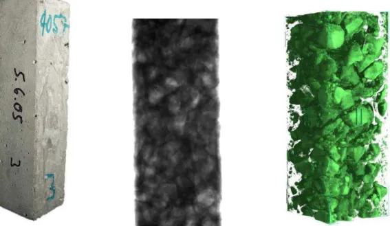
This method enables to obtain the full 3-dimen-sional information of an object under investigation. A digital neutron area detector with at least 1000 pixels per direction is required which has to be sta-tionary aligned in the beam behind the object. As shown with the example of a concrete sample in Fig. 4, tomography provides much more details compared to the radiography image, which is inte-grating all layers in beam direction. Virtual slices
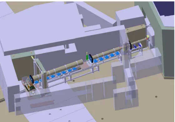
Figure 1: The neutron imaging facility ICON at beam port 52 of the spallation neutron source SINQ providing cold neutrons for different studies and industrial applications
Figure 2: Layout of the detector box for neutron imaging using a cooled CCD looking onto a neutron sensitive scintillation screen
E.H. Lehmann, A. Kaestner, and S. Hartmann
The price for a more informative data set is the longer acquisition time because the tomographic reconstruction of the third dimension by means of mathematical methods is based on at least 300 single projection which have to be taken while the object is rotated around its vertical (or horizontal) axis. The application of the reconstruction algorithm needs an advanced computer performance and takes some
extra time in the minutes to hours range, depending on the size of the data set and the used algorithm. Therefore, a single neutron transmission image can be obtained within seconds while the tomography results are available in time ranges of hours only. It is worth to decide if and how a tomography study is required for the particular problem to solve.
Figure 3: Working range of the different detection systems in respect to their geometrical alignment
Figure 4: Investigation of the composite structure of a concrete sample. Left: c photographic view, centre: neutron transmission radiography, and right: neutron tomography
Detector options with CCDs
0 0.1 0.2 0.3 0.4 0 50 100 150 200 250 300 350 400 450 Field-of-View [mm] p ixel s iz e [m m ] MAXI MICRO MIDI
Neutron tomography [4] is established at the two beam lines NEUTRA and ICON with the same per-formance as described by the data in Fig. 3. An example for the presently highest spatial resolution in our neutron tomography system is shown in Fig. 5, the lower half of a horsefly.
1.2.2 Real-Time-Imaging
The exposure time in neutron imaging can be reduced down to the range below one second by several means. On the one hand, the spatial resolu-tion can be optimized when several pixels are com-bined (binning). On the other hand, the image quality can be sacrificed and the signal-to-noise ratio limited. Beside the real neutron exposure also the read-out time has to be taken into account in fast imaging.
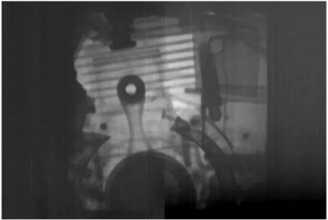
Just recently, it was possible to image in “slow motion” a combustion motor in real operation with 8.000 rpm in order to study the inner processes. While the structure is transparent for neutrons, lubri-cants and even fuel distributions become visible. This single frame in Fig. 6 was obtained by trigger-ing the detector in a short time frame of 50 µs and stacking of images with the same positions of the engine over many operation cycles.
1.2.3 Phase-contrast Imaging
Beside the absorption contrast which is usually used in transmission neutron imaging there was found another interaction mechanism which is based on the wave properties of neutrons. In this
when neutrons interact with the sample. With the help of suitable experimental setups it becomes possible to extract explicitly this phase signal [5] or to use phase effects for the enhancement of edges near weakly visible materials. This refrac-tion based phenomenon can be observed with the high resolving imaging systems, in particular when neutrons with a long wavelength λ (cold neutrons) are involved. The neutron refraction index n can be described by the following relation:
(1) Here, the atomic density N of the material under investigation and its coherent scattering cross-sec-tion σ have to be taken into account. The deviacross-sec-tion
Figure 5: Example from the high resolution neutron tomography: horsefly; length scale about 12 mm, voxel size 13.5 µm; the high contrast for organic materials can be exploited favourably in this case
Figure 6: Stroboscopic image of a combustion engine obtained in real-time mode when the rota-tion speed was about 8.000 rpm
π
λ
σ
δ
1
2
1
−
=
−
⋅
⋅
2/
=
N
coherentn
E.H. Lehmann, A. Kaestner, and S. Hartmann
1.2.4 Energy Selective Imaging
Although most of the routine neutron imaging investigations have been performed with the full spectrum of the arriving neutrons (cold or ther-mal), a narrowing of the energy band provides some new scientific aspects. As crystalline struc-tural material scatter neutrons at their lattice planes according to Bragg’s law, a visualisation of crystal-lite orientations becomes possible if the most suita-ble neutron energy is selected. Furthermore, the quantification in transmission mode becomes much more precise if only a narrow energy band has to be considered.
Future imaging facilities at pulsed neutron sources, now under construction and consideration will ena-ble a much higher degree of energy selection by using time-of-flight techniques.
2
Applications
The modern techniques in neutron imaging attract many users from the scientific and industrial com-munity. Due to a high degree of flexibility, the imaging facilities at PSI are more than booked out during the 8 month operation time per year. The access is organized for scientific users within a proposal procedure with two calls per year. Paid industrial projects are invited in a more flexible regime by direct offers of beam time on request. 2.1 Water Migration in Time and Space –
Quantification
Due to the high sensitivity of neutrons for the observation of water in porous media we performed many different studies with concrete, stones, wood
and textiles as the base structural materials in respect to their uptake and transport of moisture. However, not only the visualisation of water but also the quantification of its amount has a high importance. Unfortunately, high concentrations of hydrogen which is a strong diffuse scattering mate-rial limit the direct quantification of the water amount. Therefore, an image correction tool – QNI – was developed in order to extract the amount of secondary scattered neutrons. QNI [6] is based on Monte-Carlo simulations of the transmission pro-cess and has demonstrated its good performance within studies for soil physics and wood research [7] and materials physics [8].
QNI has been implemented mainly for thermal neu-trons and hydrogen. Future activities at PSI will be concentrated to study the effects with cold neu-trons. Furthermore, the scattering in the Bragg region will be taken into account explicitly. This is of high relevance for most of the crystalline struc-tural materials (Fe, Cu, Ni, Al, Pb, Zr, …). 2.2 Analysis of Structures
The non-invasive study of the material composi-tion and structure (geometry of the material distri-bution) is possible with neutrons either in direct transmission mode or with tomography methods for retaining the full volumetric information. Both techniques determine the quantitative information in form of a macroscopic cross-section Σ when the exponential law of attenuation is applicable:
(2)
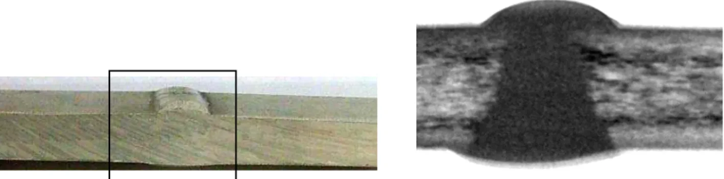
Figure 7: Edge enhancement effect; bright sky shine around the sample close to the edge by refraction in the steel injection nozzle of a Diesel engine due to the coherent scattering of cold neutrons; left a photo of the nozzle is shown
d I I / ) ln( 0 =
Σ
Three parameters need to be known: the initial beam intensity I0, the intensity behind the object I and their thickness d. The macroscopic cross-sec-tion relates to the material density ρ in the follow-ing manner:
(3) The microscopic cross-section σ describes the probability of the interaction of neutrons of a given energy with the sample material (atomic weight M) and is known in first order and tabulated. The sen-sitivity to detect and to investigate specific materi-als in high sensitivity depends clearly on the values of σ. Prominent agents for a high contrast are hydrogen and the strong absorbers B, Li, Cd or Gd. They can be detected in small amounts within bulk samples of even heavy elements.
In digital neutron imaging, each pixel (or voxel in tomography) is attributed to a Σ value. It depends on the contrast in neighbouring pixels how effec-tive it is to distinguish them and to enable it to find defects, structural changes or material edges. Prac-tical applications in this respect are the studies of adhesive layers, soldering connections, pyrotechni-cal devices, the water accumulation in elec-tro-chemical fuel cells and the gas production in Li-ion batteries.
2.3 Defects and Material Treatment In respect to defects in materials some advanced methods become interesting. If structural defects cannot be found easily due to the missing image contrast, phase contrast information might be used instead. As the wave-shift at the position of the defect is high enough, a visualisation might be enabled in some cases better. This method has to be improved more by practical experience.
Figure 8: Results of energy selective imaging (made at λ=3 Å) of the weld between two rolled Al plates; the micro-structure obtained from the manufacturing process (grains, grain size orientation) can directly be analysed while the weld itself shows a more homogenous structure
Figure 9: Example for image referencing: Three concrete samples were kept stable in their position while silane was applied for impregnation purposes. In this manner, the structure of the concrete nearly vanished while the silane amount provides a strong grey contrast. Data are taken from [9]
σ
ρ
⋅ ⋅ = M LΣ
E.H. Lehmann, A. Kaestner, and S. Hartmann
Energy selective imaging is another useful tool for material research. It has been demonstrated e.g. for rolled Al plates that the texture in the different lay-ers becomes directly visible if neutron energy bands are chosen near the Bragg edges of Al (see Fig. 8). In the same way, we can study material changes if load is applied to a sample and stress is induced.
3
Studies for Concrete Knowledge
Improvement
Digital detectors which can be aligned stationary fixed in the beam are used for pixel-wise
refer-encing in time series. In this manner, the sensitivity
for the detection and quantification of the moisture changes is increased dramatically. With this option, neutron imaging can be considered to be the most sensitive method for moisture determina-tion with best resoludetermina-tion in time and space. In particular, when the matrix of a setup (stone, wood, textile, …) remains not stable at its position, but migrates during the water uptake and loss, we are using the so-called X-TRA option at the NEUTRA beam line for referencing with an additional image data set taken under identical beam conditions. This option might overcome the problem of the sample volume change as the X-TRA images are not or only little affected by the water content.
The high flexibility for the sample size (in respect to the filed of view of the detector) and the inherent
spatial resolution (as shown in Fig. 3) are
impor-tant for the solution of different kinds of problems in building material technology and treatments. Prominent requests are the stability of water repel-lent layers, the water migration near cracks and the salt ingress into the concrete matrix.
We see a further potential in the use of energy
selec-tive methods where the contrast for the different
process components can be enhanced and the detec-tion probability can be improved. It will be a pro-cess of further test investigations to find out the best conditions for the particular study. Further potential users are invited to join us for these investigations.
4
Conclusions
Neutron imaging has been established as a valua-ble tool for non-invasive and non-destructive stud-ies in a number of laboratorstud-ies around the world. Different new techniques are still under develop-ment and will give further impact to the user
com-munity. Major challenges are the improvement of the spatial resolution, the implementation of phase-contrast methods as research tools and the use of energy-selective methods as a link to the neutron scattering techniques for the analysis of crystalline solid state materials.
References
1. E. Lehmann and H. Pleinert, The new
neu-tron radiography station at the spallation source SINQ, INSIGHT Vol. 40, No. 3,
(1998)
2. A.P. Kaestner et al., The ICON beamline - A
facility for cold neutron imaging at SINQ,
Nucl. Instr. & Meth. A, Vil. 659, Issue 1, pp. 387-393
3. E.H. Lehmann et al., The micro-setup for
neutron imaging: A major step forward to improve the spatial resolution, Nucl. Instr. &
Meth. in Phys. Res. A, Vol. 576, Issue 2-3, pp. 389-396 (2007)
4. P. Vontobel, E.H. Lehmann, R. Hassanein, G. Frei, Neutron tomography: Method and
applications, Physica B 385–386, 475–480
(2006)
5. F. Pfeiffer, C. Grünzweig, O. Bunk, G. Frei, E. Lehmann, C. David, Neutron Phase
Imag-ing and Tomography, Phys. Rev. Lett. 96,
215505 (2006)
6. R. Hassanein, Correction methods for the
quantitative evaluation of thermal neutron tomography, Dissertation 16809, ETH
Zurich, Zurich (2006)
7. E. Lehmann, P. Vontobel, P. Scherrer, P. Niemz, Application of neutron
radiogra-phy as method in the analysis of wood, Holz
Roh- Werkst 59(6):463-471 (2001a)
8. P. Zhang, F. H. Wittmann, T. Zhao, E. H. Lehmann, Neutron imaging of water
penetration into cracked steel reinforced concrete, Physica B: Condensed Matter,
405(7), 1866-1871 (2010)
9. A. Marlow, Untersuchungen zum
Silantrans-port in der Betonrandzone mittels Neutro-nenradiographie, Diploma Work, Fachhochschule Karlsruhe (2005)
Received January 5, 2012
Dr. Eberhard Helmar Lehmann
1970-1974: study in physics at the University of Leipzig (Germany) – diploma as “Dipl.-Physicist”, Topic: “Molecular dynamic calculations of proteins” ; 1983: Dr. rer. nat. at the German Academy of Science, Berlin; Topic: “Cross-section data of construction mate-rials for the fast breeder reactor by reactivity measurements”.
Present Position: Group Leader “Neutron Imaging & Activation” of the Department Spalla-tion Neutron Source, Paul Scherrer Institut, Switzerland.
Field of Specialisation: Neutron Physics for Research Reactors and Spallation Sources, Applications of Neutrons in Science and Industry; Neutron Imaging, Irradiation Technology. Experience: 1976-1990: research in reactor physics for fast breeders, experimental work at different reactor stations in several countries, calculations of reactor parameters with differ-ent reactor codes; 1991-1995: reactor physicist at the research reactor SAPHIR, responsibil-ity for core design and applications; since 1995: responsibilresponsibil-ity for non-diffractive applications and spallation neutron physics of the spallation neutron source SINQ at the Paul Scherrer Institute and for neutron utilisation around the source.
E-mail: [email protected]
Dr. Anders Kaestner was born in Helsingborg, Sweden, in 1971. He is a beamline scientist
at the cold neutron imaging beamline (ICON) at Paul Scherrer Institut, Switzerland. He stud-ied computer systems engineering with specialization to mechatronics at Halmstad Univer-sity, Sweden, and received a MSc. in 1997. He started working with imaging using microwaves during his masters thesis. The work with imaging and image processing was continued with a PhD in Signal Processing at Chalmers Institute of Technology, Gothenburg, Sweden, in 2002. The work with image processing continued as a postdoc working with image processing tasks for soil science in the soil physics group at the institute for terrestrial ecology, Swiss Federal Institute of Technology in Zürich, Switzerland. Special fields of inter-est are computed tomography and image enhancement. He is currently a board member of the international society for neutron radiology.
Stefan Hartmann has a mechanical engineering degree from UAS in Windisch. Since 2004
he works with neutron imaging at the spallation neutron source SINQ as well as with the development and improvement of its neutron imaging beam line process control systems.