Publisher’s version / Version de l'éditeur:
Construction Canada, 32, 2, pp. 40, 42-44,46, 1990-03
READ THESE TERMS AND CONDITIONS CAREFULLY BEFORE USING THIS WEBSITE.
https://nrc-publications.canada.ca/eng/copyright
Vous avez des questions? Nous pouvons vous aider. Pour communiquer directement avec un auteur, consultez la
première page de la revue dans laquelle son article a été publié afin de trouver ses coordonnées. Si vous n’arrivez
Questions? Contact the NRC Publications Archive team at
PublicationsArchive-ArchivesPublications@nrc-cnrc.gc.ca. If you wish to email the authors directly, please see the first page of the publication for their contact information.
NRC Publications Archive
Archives des publications du CNRC
This publication could be one of several versions: author’s original, accepted manuscript or the publisher’s version. / La version de cette publication peut être l’une des suivantes : la version prépublication de l’auteur, la version acceptée du manuscrit ou la version de l’éditeur.
Access and use of this website and the material on it are subject to the Terms and Conditions set forth at
Facts and fictions of rain screen walls
Rousseau, M. Z.
https://publications-cnrc.canada.ca/fra/droits
L’accès à ce site Web et l’utilisation de son contenu sont assujettis aux conditions présentées dans le site LISEZ CES CONDITIONS ATTENTIVEMENT AVANT D’UTILISER CE SITE WEB.
NRC Publications Record / Notice d'Archives des publications de CNRC:
https://nrc-publications.canada.ca/eng/view/object/?id=3734fcae-528d-4445-bde7-d17883eb9c7b https://publications-cnrc.canada.ca/fra/voir/objet/?id=3734fcae-528d-4445-bde7-d17883eb9c7bSer
TH1
N21d
n0.l6&6
,I
National Research
Conseil pational
6
-
Council Canada
de recherches Canada
- - - -
Institute for
lnstitut de
Research in
recherche en
Construction
construction
Facts
and
Fictions of Rain Screen Walls
by Madeleine
Z. Rousseau
ANALYZEDAppeared in
Construction Canada 90 03
Volume
32,
Number 2
March/April
1990p. 40-47
(IRC Paper No. 1666)
Reprinted with permission from
Construction Canada
NRCC 32332
r-"--
- -
1 - n + ""0 *, 3 T l ! - ? <i
LIP^i.?y
i
-
A1
I
SF?
1; lago
-
I
2
C
-?4r ~e-
p- ; qTi
1
F
- - 8Canad3
/ m
23
b53
Abstract
Pressure equalization across the exterior cladding of exterior walls is an important feature
for the application of the rain screen principle which aims at minimizing rain entry into
exterior walls. Confusion exists in the industry about the difference between cavity walls
and rain screen walls. The papa focuses on the wall components that contribute to obtain
pressure equalization across the outside cladding, that is, a compartmented cavity behind
the cladding, a rigid air barrier assembly, and adequate venting
area
of the cladding in
relation to the leakage area of the
air
barrier. The results of
IRC
laboratory testing and field
monitoring of two buildings of different construction for pressure-equalization performance
are
briefly presented, with discussion of possible reduction of the design wind loads for
rain screen cladding.
KEY
WORDS
exterior cladding, rain screen, wall, masonry, precast concrete panel, wail cavity, pressure
equalization, wind loads, air barrier
L'Cquilibrage de la pression de part et d'autre du parement exttrieur des faqades est une
condition importante pour l'application du p ~ c i p e
du pare-pluie, qui vise A empCcher le
plus possible la pluie de Nnttrer
dans
les murs.
La
diff6rence enue un mur creux et un mur
pare-pluie n'est pas claire pour l'industrie. Cet article porte principalement sur les ClCments
de mur qui contribuent
A
assurer l'huilibrage de la pression de part et d'aum du parement
extdrieur, c'est-&-dire une lame d'air compartirnentde derrike le parement, un pare-air rigide
et une surface de ventilation du parement variant selon la surface de fuite du pare-air.
L'auteure pdsente bribvement les r6sultats d'essais en laboratoire et de monitorage in situ
portant sur deux batirnents de construction diffkrente et destinks
A
tvaluer leur performance
au point de vue huilibrage des pressions, et elle examine la possibilitk de dduire les
surchaxges de vent de calcul dans le cas des parements pare-pluie.
Facts and Fictions
of
Rain Screen
W a l l s
By Madeleine Z. Rousseau, I M W C
Rain penetration through walls can damage the building envelope. Corrosion of anchors of exterior cladding, efflorescence on masonry, damage and staining of interior finishes are just a few examples of problems due to "mismanaged" rain. As if that is not enough, it can also affect the appearance, the function and the comfort of the space, factors that translate into disruption of the occupants (loss of productivity), into loss of profit for the owner or manager of rented office and commercial space and probably decreased market value.
Proper control of rain penetration is easier and less costly to obtain at the design and construction stages than later on during occu- pancy. In the latter case symptoms showing up seemingly at random in many rooms (where expensive equipment can be located) of the twelfth floor of a 15-storey building can be distressing to the building owner/manager and to the users of the space. Designers and builders (and building owners) must under- stand what is required to control rain penetration through exterior walls.
rain screen walls. Here is an example of how subtly this often appears. When possible causes of rain leakage problems are discussed, the question eventually arises of whether the design and construction of the walls apply the rain screen principle. Quite often, the response is "Yes, they do: there is a drained cavity behind the cladding". Sony '
. . .
but this fits the description of a cavity wall, not a rain screen wall. A "rain screen wall" is designed and built according to what Kirby Garden referred to as the "Open rain screen principle"', whose basic premise is the control ofALL
forces that can carry rain to the inside.
Now a heated debate on termi- nology usually starts! It is clear in' my mind that a "rain screen wall" is a wall to which the "rain screen principld" is applied; this ex- pression refers to a given package of requirements set out in Garden's published material twenty-five years ago. Others argue that any wall that uses the cladding as a screen for rain, such as a cavity wall, can be called a rain screen wall. Usually the debate cools off
lies. In my view it is a redundant expression, but at least it ends temporarily, arguments on terms so we can focus on
HOW
to build such a wall.Cavity
W a l l s
With respect to rain penetration, the concept of cavity walls is based upon the control of some of the forces acting on the cladding i.e. gravity, surface tension,
capillary action and rain drop momentum. Decades ago it was used for masonry construction to reduce dampness of inside wall surfacesZ (Fig. I). To control rain entry by capillarity, a large cavity -(50 to 75 mm wide) was introduced
between the outer and inner layers
when the expression "pressure-
*1ieunderstood
Principles
eaualized rain screen wall., - , is used.
Inquiries from builders, architects The term "pressure-equalized" rain
and engineers suggest that drained screen is particularly useful in Fig. 1: Masonry cavity wall cavity walls are often confused with that it emphasizes what is ignored section, a s designed
25
years agoor confused, as well as what
differentiates it from a drained of masonry: water entering the outer
lMadeleinc Z* Rousseaup MRAICp cavity wall. Pressure equalization in layer would not bridge the large is a research officer for the Institute the cavity behind the cladding: gap to reach the inside layer. Water
far
Research in Construction7 NRC1 this is where the difference between would then run down on a surface Ottawa.a rain screen wall and a cavity wall . of the cavity to the bottom, and
*
42be collected by a flashing directing the water to little drains, the weep holes. At openings and interfaces with other components such as windows, rain drops can find their wav deep into the joint unless a shield (not airtight or watertight) is installed on the outside of the joint to "break" the momentum of the drop: this took care of the rain drop momentum. Surface tension, another manifestation of capillary force, can allow water to go up in a horizontal joint; to counteract this force, a sudden change in direction in the material allows the rain drop to detach from the surface. A groove in a thick material or a labyrinth in a thin one are examples of ways to reduce rain entry by surface tension. Horizontal joints should have a positive slope to drain outward so that gravity works for you. This "drained cavity" approach was later applied to other types of wall besides masonry walls, with varying details depending on the system. As impervious prefabricated cladding panel systems have entered the market, the proper detailing of joints has become critical to the control of all the forces by which rain enters exterior walls..
Even though an exterior wall includes a flashed and drained cavity behind the cladding as well as rain deflectors, it may not control rain penetration adequately because a significant force at play has been ignored: that is, a difference in air pressure across the cladding. This causes infiltration of air and water on windward facades through joints, small pores, gaps, cracks, poorly bonded surfaces and openings that exist or develop during the life of the cladding.
Pressure-Equalized Rain
Screen Walls
The rain screen principle entails the control of all the forces handled by a drained cavity wall plus the
air pressure difference acting across the cladding. To many designers and contractors, believing that AIR pressure difference across claddings causes WATER entry is hard to comprehend.
During a rain storm, air infil- tration through porous cladding, its joints, cracks and gaps is a great vehicle for water to get a free ride into the enclosure. The rain screen principle recognizes this harmful potential and addresses the control of air pressure difference across exterior cladding assemblies.
No one can stop the wind from blowing! But wall design should be such that the cladding experiences almost no net pressure difference due to wind. Imagine t.hat wind pressure on cladding could practicdly cancel itself if the is trans- ferred to the back of the cladding.
. .
in the cavity-
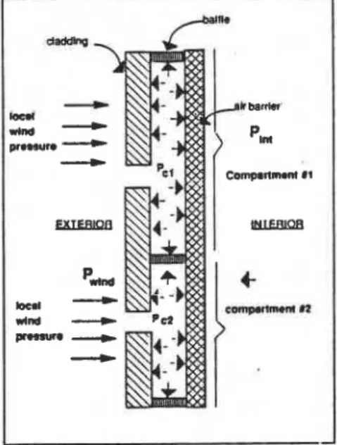
(Fig. 2). For the cavityFig. 2: Equalization of pressure
across the cladding needs: a rigid air barrier; a cavity behind the cladding; cavity baffles; and exterior vents in the cladding
to respond quickly to fluctuations in wind pressure, and for proper management of wind in this cavity,
air flow in the cavity must be minimal. Indeed all you want is to pump in a little volume of outside air to equalize the pressure across the cladding. For this to happen, you need a rigid air barrier; a cavity behind the cladding broken down vertically. and horizontally into tight compartments of varying sizes; a large venting area connecting the cavity to the outside; and a somewhat impervious cladding. This is far from the myth spread in the industry which claims that simply venting a cavity (no matter how big the cavity behind the exterior cladding
.
. .
no matter how leaky the inner wall] does the trick of applying the rain screenprinciple.
Let's examine some of these needs:
A Rigid Air Barrier System
Wind induces large air pressure difference across exterior walls, especially during gusty wind conditions while mechanical ven- tilation and stack effect cause smaller but- steady pressure dif- ferentials. Air leakage through a wall system prevents the outside pressure from equalizing across the cladding. This could be com- pared to trying to inflate a balloon also perforated at the other end: to increase the pressure in the balloon, the easiest way is to make a knot with the perforated end so it is sealed. In construction, this common sense action is called building an air barrier system! An air barrier system will control air flow through the wall system. The balloon example stops working here: the air barrier should be rigid to keep the volume of the cavity constant. A constant volume helps the cavity "bounce back" quickly in response to rapid pressure fluctuations (during wind gusting), e.g. reducing time lag for pressure equalization across the cladding. A
flexible membrane deflecting in the cavity under wind pressure can promote some pumping in of outside air (and rain). Besides, the air barrier system should be rigid for its own sake and durability: this way the pressure loads get uniformly distributed on its surface rather than concentrating fatigue stress at the supports.
A Cavity
A cavity behind the cladding acts as a site for the outside pressure to be transferred, a capillary break and a channel for drainage. The net width of the cavity should be about 25 mm. Allowances for site tolerances and possible blockage of the cavity with debris and (mortar for masonry cladding) should be made. The larger the cavity, the more venting needed to obtain an equalization of pressure in it.
A Compartmented Cavity
Lateral air flow within the cavity can occur without air passing through the wall. This air flow is due to variations in wind pressures over the height, width and geometry of the facade: outside air (and rain, remember) flows into the cavity through vents in locations of higher pressure, and out of the cavity through vents in areas of lower pressure, messing around in the cavity (and insulation possibly) on its way out. Corners and tops of buildings are usually exposed to extremely sharp pressure gradients,
;
where the windward side is exposed to high positive pressure and the other side is subjected to high negative pressure. Pressure equali- zation across the exterior cladding cannot be achieved without proper control of lateral air flow within the cavity3. It should be divided into a series of tight compartments; then the range of pressure variations that each compartment senses is reduced, and chances of getting aquick equalization of pressure in each compartment will increase. How large should the compart- ments be? Their size should be based on the pressure ranges they are likely to experience. Since wind pressures are usually more uniform in the center of a flat facade than at the corners, com- partments can be larger in the centre and should be smaller at the corners (a wind tunnel study stressed the importance of compartmenting corners3]. Garden' suggested compartments every 1.2 m (4 ft) at the ends and tops of walls in a 6 m (20-ft) wide perimeter zone, and on 3 to 6 m (10 to 20-ft) centres in both directions over the central portion (Fig. 3). Existing com- ponents of walls can act as cavity
wall designed as a pressure- equalized rain screen wall system indicated that mechanically attached extruded polystyrene foam strips suited this wall system in providing the features required to reduce lateral air flow and in remaining in place. It may. be that strips of wood, sheet metal and rigid plastic. may also prove suitable as long as they do not interfere with other requirements for the wall such as fire and heat flow controls. In 1989 Canada Mortgage and Housing Corporation (Jacques Rousseau at (613) 748-2013) initiated a project to define better the features required for rain penetration control using the rain screen principle as applied to typical claddings (masonry), stucco. clapboard) used for wood-
Fig. 3: Compartmentation over a flat facade due to wind pressure
variations
baffles: windows, flashings, shelf frame construction. The project angles, balconies, furring strips etc. involves laboratory experiments At this stage no guidelines exist under steady-state and some on the airtightness, the strength and dynamic wind loading conditions. the connections of these cavity Venting
baffles. Field monitoring of a To equalize the pressure between precast concrete sandwich panel two environments, these must be Construction Canada 90 03
connected somehow: venting holes connect the cavity to outside. Vents should preferably be located at the bottom of the compartment so they also drain it. All vents of a compartment~should be placed at the same height to avoid air flow loops. The vents holes should be at least 10 mm in diameter to prevent formation of a film of water over the holes, which would reduce the useful venting size.
The amount of venting required in the cladding depends upon the
, tightness of other components of
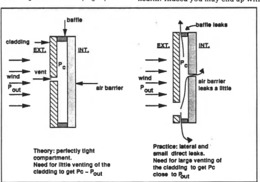
the cavity, i.e. the air barrier system and the baffles. The cladding should be much leakier than the other layers of the compartment (air barrier
+
baffles) so that the cavity pressure is closer to outside pressure than to inside pressure, and pressure drop across the cladding is minimized_(Fig. 4).However a quite small, tight and rigid compartment was used in the experiments, and other types of wall design may call for different ratios. Another study suggests 25 to
40 times more venting than leakage6. Most often the cavity baffles will not be that airtight and to account for this, the cladding venting should be even larger than those figures. This approach to venting is quite different from that used for cavity walls, where venting is rather small.
Therefore the tighter the compartment, the less venting of the cladding required for a rapid equalization of pressure. The reverse statement is also technically correct by itself: the leakier the air barrier, the leakier the cladding has to be, but misinterpreted, this state- ment can be hazardous to your health! Indeed you may end up with
claddlng ' E X L _+ __)_
-
vent __CI wlnd wlnd __C-
r banler __C -ap __C _Ic.Theory: perfectly llght Prsctka W r a l and ' compartment. m a l l dtrect leaks. Need for llttle ventlng of the Nwd for Brge ventlng d claddlng to get Pc
-
PWt the dadfJtng clos, to Pout to get PcFig. 4: Need for venting of the cladding us leakage
of the compartment
LattaJ calculated that a 10:l ratio a leaky wall and its aasociated array for cladding leakagelair barrier of potential problems, e.g. uncon- leakage could be satisfactory. trolled flows of moisture, dust. Recently IRC laboratory experi- noise and heat. So don't neglect ments involving tight curtain wall provision of a proper air barrier systems confirmed this figure5. on the basis that all you need is to
open the tap on the cladding venting, because this could cause problems. The air barrier system should be as tight as possible, whether it is for the control of rain, condensation or noise. After having evaluated the air barrier tightness, the venting of the cladding should be established to fit the recommended ratio. To obtain the airtightness value of the air barrier component proposed, testing of a mock-up wall com- partment may be required since little information on the range of airtightness of generic as-built wall air barrier components is available.
Wind Loading on
the
Cladding
The proper application of the rain screen principle reduces not only the water loads on the cladding but also wind loads. Indeed the foundation of the principle is the achievement of the same pressure on both sides of the cladding. In theory, a well performing rain screen wall should have all wind loads sustained by the air barrier system, and consequently the structural requirement for the exterior cladding and its anchorage could be greatly reduced. In practice this may happen under sustained pressure in a well designed rain screen wall. However under gusty wind conditions, the cladding does sustain some wind loading because of time lag in getting pressure equalization across the wall, as proven by monitoring two buildings for a year and a half7 while a wind tunnel investigation was performed on similar walls3.
Building A, a high-rise structure, had precast concrete sandwich wails with a very rigid air barrier (115 mm cast concrete, very small comparhnents, tight baffles and large venting (Fig. 5)8. A static pressure test using the HVAC equipment on a calm day indicated
The qualification "well-designed and built" is very critical to the wind loading on the cladding as we
POLYSTYRENE INSULATION found out by monitoring building
B. Building B has a masonry cladding, unusually large com-
(1 ? 5 mm CAST CONCRETE) partments, little venting and a
flexible air barrier llnsupported on
VENTING AREA one side (Fig. 6). What might look
at a glance like a pressured-
VENTING AREA WINDOW OPENING equalized rain screen wall did not
perform as such, and the negative
COMPRESSED GASKET wind pressure loads did n n t get
transferred to the air barrier. In positive pressure, the cavity pressure followed the outside pressure but without ever equalizing
Fig. 5 : Building A. Isometric view of a compartment it. In this case the cladding should
be designed to sustain 100% of the
46 Construction Canada 90 03
design wind loads.
that all the pressure drop could could be designea for 70% of the These are fairly serious impli- occur across the air barrier: so this design load. cations for the structural design
implies the air barrier system was of cladding systems. At this stage
well designed and built. In general, under sustained (several seconds o r . more) wind loading, the loads on the cladding were small (up to 50-60 Pa); this indicated that the potential for rain entry is minimized. However rapid changes in outside
air pressure, especially under E
negative loading (suction), resulted E
in pressure difference of at least
8
CUC\1
150 Pa across the cladding, due to the time lag response of the cavity. The largest transient pressure measured across the cladding was
285 Pa. This negative load on the cladding does not affect the rain
penetration potential in the walls E E
but the peak short-lived pressures 0 0
to be sustained by the cladding and Z
its anchors do affect their structural design. The measurements indicate
that the rain screen and its E E
attachments may have to withstand
8
as much as 75% of the design
Z
pressure for the whole wall assembly. The results of the wind tunnel investigations of this wall system brought similar figures,
indicating the cladding of a "well Fig. 6:
designed and built" rain screen wall Building B. Geometry o j the compartment
L
II
1
wind tunnel studies should be performed on the proposed design if relief of wind loading pressure on cladding is sought by applying the pressure-equalized rain screen
I
I
principle.Need
for
guidelines
Many questions are still pending about the practical considerations to design a pressure-equalized rain screen wall. The maximum sizes of compartments should be the object of further lab and field work since Garden came out with rough figures twenty five years ago. The types of baffles, their attachment and tightness should be tested for their efficiency, ease of installation, and possible trade-off with other criteria of performance. Joints between large prefabricated panels and their interface with other components such as windows can also apply the rai.n screen principle; guidelines
in the air barrier system and its anchorage system. You may ask, why bother switching the loads from one component to the other? Only a systematic and consistent
approach to air and rain flows will produce durable exterior walls that can meet harmoniously all criteria of performance set by designers for the benefits of building owners and users. This systematic approach calls for a continuous air barher system that not only sustains wind loads, but controls air leakage, moisture flow, noise, pollutants etc. in a durable fashion; it is practically a prerequisite for rain penetration control.
1. Garden. Kirby. Rain penetration and its
control, National Research Council
Canada. Division of Building Research, (Canadian Building Digest no 40), 1963, 4 p.
on their design sho&-fbe developed. 2. ~ i t c h i e , ~ . Cavity walls, National Research
A laboratory testing procedure Council Canada. Division of Building
Research. Canadian Building Digest no 21,
using dynamic wind loading and
~ ~ 1961, 4 0.
water sprays would allow the 3. Irwin. P.A., G.D. Schuyler and M.A.
evaluation of mock-up design; IRC Wawzonek. [Morrison-Hersfield Limited
is presently working on a project Consulting Engineers), A wind tunnel
that requires the development of investigation of rain screen wall systems.
NRCC contract no 15SR.31944-3-0014
such a procedure. The rigidity April 1984, 127 p.
of the air barrier in relation to that 4. Latta, Ken, Walls, windows and roofs for
of the claddinn could be investi-
-
the Canadian climate. National Researchgated. ~h~ best way to provide large Council of Canada, Division of Building
venting without causing direct 5. Ganguli Research, (NRCC 13487). 1973. p.75. U, and R.L. Quirouette. Pressure rain entry should also be looked at. equalization performance o f a metal and
Conclu8ion
glass curtain wall. Proceedings 1987 CSCEThe application of the pressure- Centennial Conference Montr6al. Quebec.
May 19-22 1987, vol. 1. p.127-144.
equalized rain screen principle lNRCC 290241.
requires more attention. detailing 6. ~ i l l i ~ , 1.R. and D.W. Cheetharn. The
and care from the designer and prevention of rain pcanetration thmugh
builder but is likely to ieauire less external uraLLv and ~oinls by means of
maintenance and care from the pressure equalization. Building and
Environment, vol. 19. no 2. pp.81-91,1964.
owne~/manager during the service 7, Brown.
w
C. M z Riusseau andw
Alife of the building.
- - .
Dalgliesh, Field Testin# of pressure-
equalized rain screen walls, presented at the
Compared to traditional practice, Exterior Walls Symposium, Chicago. the proper application of the rain 1989. T o be published by ASTM as a
screen ~ r i n c i ~ l e can result in a Special Technical Publication.
reduction of strength required for 8. Ganguli, U. and W.A. Dalgliesh, Wind
the cladding and its anchorage Pressures on Open Rain Screen Walls:
Place Air Canada. Journal of Structural
system, which must go hand-to- Engineering, vol. 114. no 3. March 1988. hand with an increase of strength p.64z-6s6, (NRCC 288.59).
This paper is being distributed in reprint form by the Institute for Research in Construction. A list of building practice and research publications available from the Institute may be obtained by writing to Publications Section, Institute for Research in Construction, National Research Council .of Canada, Ottawa, Ontario, KIA 0R6.
Ce
document est distribue sous forme de ti+&-part par1'Institut de recherche en construction. On peut obtenir une liste des publications de 1'Institut portant sur les techniques ou les recherches en matiere de Mtiment en-
Ccrivant & la Section des publications, Institut de
recherche en construction, Conseil national de