READ THESE TERMS AND CONDITIONS CAREFULLY BEFORE USING THIS WEBSITE. https://nrc-publications.canada.ca/eng/copyright
Vous avez des questions? Nous pouvons vous aider. Pour communiquer directement avec un auteur, consultez la première page de la revue dans laquelle son article a été publié afin de trouver ses coordonnées. Si vous n’arrivez pas à les repérer, communiquez avec nous à PublicationsArchive-ArchivesPublications@nrc-cnrc.gc.ca.
Questions? Contact the NRC Publications Archive team at
PublicationsArchive-ArchivesPublications@nrc-cnrc.gc.ca. If you wish to email the authors directly, please see the first page of the publication for their contact information.
NRC Publications Archive
Archives des publications du CNRC
This publication could be one of several versions: author’s original, accepted manuscript or the publisher’s version. / La version de cette publication peut être l’une des suivantes : la version prépublication de l’auteur, la version acceptée du manuscrit ou la version de l’éditeur.
Access and use of this website and the material on it are subject to the Terms and Conditions set forth at
Overview of research underway at the Institute for Marine Dynamics
related to the investigation of interactions between floating structures
and bergy bits
Cumming, D.; Gagnon, R. E.; Derradji-Aouat, A.; Jones, S. J.
https://publications-cnrc.canada.ca/fra/droits
L’accès à ce site Web et l’utilisation de son contenu sont assujettis aux conditions présentées dans le site LISEZ CES CONDITIONS ATTENTIVEMENT AVANT D’UTILISER CE SITE WEB.
NRC Publications Record / Notice d'Archives des publications de CNRC:
https://nrc-publications.canada.ca/eng/view/object/?id=db5c38fb-5183-4e8a-9781-1c8b06bfeb49 https://publications-cnrc.canada.ca/fra/voir/objet/?id=db5c38fb-5183-4e8a-9781-1c8b06bfeb49
OVERVIEW OF RESEARCH UNDERWAY AT THE
INSTITUTE FOR MARINE DYNAMICS RELATED TO
THE INVESTIGATION OF INTERACTIONS BETWEEN
FLOATING STRUCTURES AND BERGY BITS
D. Cumming, R. Gagnon, A. Derradji, & S. Jones
ABSTRACT
Hydrocarbon exploration and development activity is expanding rapidly off the Canadian East Coast. Mitigating the problems resulting from bergy bits is an important concern to companies operating both moored structures and shuttle tankers in these ice infested waters. This paper provides an overview of the multi-year research program currently underway at the Institute for Marine Dynamics (IMD) to investigate issues related to interactions between floating structures and bergy bits. The overview includes a description of the dedicated experiments carried out to: • Investigate the hydrodynamic interaction between a physical ship model towed over a range
of speeds from slow speed, simulating a ship moored in current, up to a typical tanker transit speed on free-floating bergy bit models in calm water;
• Quantify the wave induced motions and drift rate of bergy bit models free-floating in open water;
• Investigate the hydrodynamic interaction forces between a bergy bit model drifting in waves in close proximity to a ship being towed over a range of speeds from slow speed, simulating a ship moored in current, up to a typical tanker transit speed;
• Assess the forces and pressures arising from a collision between a marine structure and a growler using actual iceberg ice;
• Determine the material properties of iceberg ice at high strain rates by conducting high speed uniaxial compression tests; and
• Describe the impact of ships with bergy bits through numerical simulations and to validate the results.
Example preliminary experimental results are included. Plans for full scale trials scheduled for the Summer 2001 to measure loads and pressures during impacts with bergy bits using the CCGS Terry Fox are also described. This research is supported by the Institute for Marine Dynamics, the Program of Energy Research and Development (PERD), Mobil Oil Canada Properties, on behalf of the owners of the M/T Kometik Tanker, Petro-Canada, as Operator of Terra Nova, and the Regional Transportation Steering Committee (Representation from Chevron Canada Resources Ltd., ExxonMobil Canada, Husky Oil Operations Ltd., Mosbacher Operations Ltd., Murphy Oil Company Ltd., Norsk Hydro Oil and Gas Canada Inc., Petro-Canada).
INTRODUCTION
In November 1995 the Program of Energy Research and Development (PERD), through the National Energy Board (NEB), requested that IMD carry out a research project to determine the hydrodynamic influence on impact forces imparted to a floating structure resulting from a collision with an ice mass of arbitrary size and shape. A staged approach was planned that included a review of existing numerical and analytical techniques to
predict the hydrodynamics, a series of physical model tests and full scale trials to validate the prediction techniques, and finally the assembly of a computer model to simulate the collision validated using model and full scale data. The project has evolved considerably since its initial conception both in technical aspects and the level of support (as noted above). IMD has now completed about 3 years of the 4 year research program.
The results of the first stage of the project, the review of the existing numerical and analytical techniques, are outlined in Wu (1996) and Murray (1996). A number of critical areas warranting further research were identified in these references and it became apparent that the available analytical techniques were inadequate to model bergy bit/structure interaction. The initial review did not consider computational hydrodynamic (CH) techniques, however, and a subsequent review indicated that the most promising approach, given rapid developments in computer hardware and software, would be to use CH. Therefore, a series of systematic physical model experiments followed by full scale trials was planned to permit validation of a CH model. Besides the validation of the CH model, the test data would provide a database from which hydrodynamic coefficients could be derived for use in a semi-empirical model in the event that the CH approach proved impractical. In support of this effort, the following series of physical model tests in IMD’s 200 m long Towing Tank were carried out in 1998/99:
1. Determination of the hydrodynamic drag coefficient of bergy bit models and the interaction with a moored ship model in calm water;
2. Assessment of the motion damping coefficients of the bergy bit models;
3. Investigation of the hydrodynamic interaction between a ship model towed over a range of speeds from slow speed simulating a ship moored in current up to a typical tanker transit speed on free-floating bergy bit models in calm water;
4. Quantifing the wave induced motions and drift rate of bergy bit models free-floating in open water; and 5. Investigation of the hydrodynamic interaction forces
between an bergy bit model drifting in waves in close proximity to a ship model being towed over a range of speeds from slow speed simulating a ship moored in current up to a typical tanker transit speed.
In addition, experiments to quantify growler impact loads using actual iceberg ice were carried out in the IMD Ice Tank in 1999 and experiments in the IMD Large Cold Room to investigate the material properties of iceberg ice at high strain rates were completed in 2000. Efforts to develop and validate a suitable CH model are ongoing. Sea trials involving full scale collisions with bergy bits using the Canadian Coast Guard heavy icebreaker CCGS ‘Terry Fox’ are planned for the summer of 2001. This paper provides an overview of this complex project including example results from the experimental program completed to date although it should be noted that the project data is subject to a proprietary period.
TOWING TANK EXPERIMENTS
The Towing Tank experiments were designed to gain further understanding of the hydrodynamic component of the interaction between free floating ice masses and floating structures, validate a selected CH model as well as compile a database from which hydrodynamic coefficients could be derived for use in a semi-empirical model in the event that a CH model proved impractical. Five distinct test scenarios were executed.
Description of Physical Models
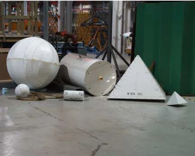
Nine bergy bit models, three different sizes (large, medium and small) and three different simple geometric shapes (four sided pyramid, right circular cylinder, and sphere) were fabricated for these experiments. The models typically displaced 7 – 10 kg (small), 400 – 800 kg (medium) and 5.5 – 10 tonnes (large). To provide some sense of physical size, diameters for the small, medium and large spherical models were 0.3 m, 1.2 m, and 2.8 m respectively. Every effort was made to fabricate homogeneous models of the correct specific gravity (0.88 – 0.90) such that the scaled inertial properties matched those of real icebergs. The three smallest bergy bits were milled from laminations of RENSHAPE 550 bonded together with epoxy. The outer shell of the larger bergy bit models were made from either Glass Reinforced Plastic (GRP) (spherical models) or High Density Polyethylene (HDPE) (cylindrical and pyramidal models). These models were free flooding and completely filled with lengths of 4 inch diameter plastic pipe bolted together to baffle entrapped water movement. In an effort to obtain the desired specific gravity while preserving the homogeneity of the model mass properties, foam inserts were fastened into the full length of each internal pipe. Photographs of the small and medium bergy bit models are provided in Figure 1 while a detailed description of the construction is given by Riche (1999).
A 1:41 scale generic tanker model was fabricated to lines assumed to be typical for a 220,000 t tanker. The principal dimensions of the model were:
LOA = 7.198 m LBP = 7.003 m BWL = 1.159 m Draft = 0.435 m Displacement = 3.064 t
The bare hull included a bulbous bow, long wallsided midbody and centerline skeg. The only appendage added was a representative rudder fixed on the longitudinal centerline. No propulsion system was
fitted. Note that the bergy bit models were arbitrarily set to the same scale as the tanker model.
Test Type #1: Determination of Hydrodynamic Drag Coefficients and Interaction with a Moored Structure
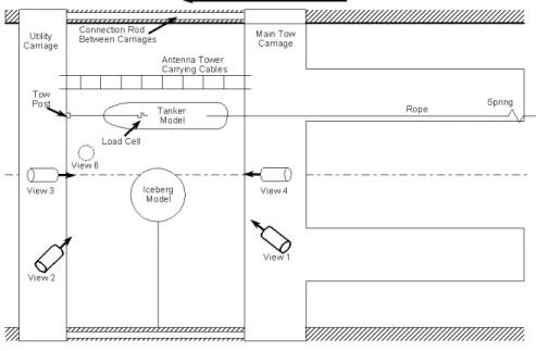
The hydrodynamic drag coefficients of the bergy bit models and interaction with a moored structure were determined by towing the bergy bit models in open water and in close proximity adjacent to the moored tanker model in calm water. The tanker model was moored using a spring mooring arrangement between two rigid beams parallel to the Towing Tank wall at roughly the longitudinal midpoint of the tank as illustrated in Figure 2. The planar (X, Y) position of the tanker model was measured using four linear displacement transducers. The forward and aft tanker mooring loads were also measured. The bergy bit models were towed using a complex two carriage towing arrangement depicted in Figure 3. The tow force, tow carriage longitudinal displacement and speed were measured. The two carriage arrangement was necessary to facilitate including a restraining pretension load using a spring/mass system on a vertical restraining post to restrain the models longitudinally and mitigate acceleration/deceleration induced transient loads. To maintain a constant distance between the moored tanker model and the towed bergy bit model, a lateral constraint system consisting of four wire cables extending to the bergy bit models from parallel beams fitted between the two carriages was devised. The in-line loads on these restraining cables were also measured.
The test matrix for these experiments included:
• three lateral separation distances between the bergy bit models and tanker model (only two lateral separation distances were possible for the large bergy bit models due to the 12 m width limitation of the Towing Tank);
• bergy bit model tow orientations - spherical models – one orientation, cylindrical models – two orientations and three orientations for the pyramid shaped models;
• three bergy bit towing speeds in open water and adjacent to the tanker model; and
• three bergy bit model accelerations in open water and adjacent to the tanker model.
Test Type #2: Bergy Bit Model Damping Coefficient Experiments
Bergy bit model damping experiments were carried out on an opportunity basis throughout the test program by manually depressing the free-floating models and measuring the variation in motion displacement until the motions subsided. Model motions were measured using
a QUALYSIS optical measurement system described in Sullivan (1997) acting on an array of spherical reflectors attached using lightweight carbon fibre rods to the top of each bergy bit model (see Figure 4). Ideally, motion decay experiments were carried out for roll, pitch and heave for each model although this was not always possible due to either the large size or geometry of the models.
Test Type #3: Determination of the Hydrodynamic Interaction Between a Towed Ship Model on a Free-Floating Bergy Bit
The hydrodynamic interaction between a ship model towed over a range of speeds from slow speed simulating a ship moored in current up to a typical tanker transit speed on a free-floating bergy bit model in calm water were investigated. No tanker propulsion system induced flow was included as the model was not fitted with a propulsion system.
A two carriage arrangement similar to what was used for Test #1 was also used for these experiments (see Figure 5). The tanker model was towed from a point on the main deck about 1/3 the length back from the bow. A nominal 50 N spring loaded restraining pretension was applied to the model stern for improved directional stability. Parameters measured on the tanker model for these experiments included surge, sway and heave linear accelerations at the model center of buoyancy, pitch, roll and yaw angle, in addition to the tow force.
Although the bergy bit models were free-floating for these experiments, a system of ropes was necessary to manually position them prior to the start of each run to ensure the desired lateral separation distance between the bergy bit models and the tanker model was obtained. Bergy bit motions with six degrees of freedom were measured using the QUALYSIS system.
The test matrix for these experiments included:
• varying the model bergy bit floating orientations – spherical models – one orientation, cylindrical and pyramid shaped models – two orientations each;
• a wide range of separation distances between the bergy bit models and the tanker model ranged from 0.35 – 1.55 m (small models), 1.44 – 2.579 m (medium models) and 1.66 – 2.8 m (large models); and
• tanker forward speeds corresponding to 1, 3, and 5 knots full scale (range of current speeds) and 10 and 15 knots full scale (representative tanker transit speeds).
Test Type #4: Quantifying the Wave Induced Motions and Drift Rate of Bergy Bit Models Free-Floating in Open Water
For these experiments, bergy bit model motions with six degrees of freedom were measured using QUALYSIS as the models were permitted to freely drift in waves down the Towing Tank. Only four of the bergy bit models were investigated – the large pyramid shaped model and all three spherical shaped models. The tow carriage operator was tasked with the responsibility of manually adjusting the speed of the carriage to match the model drift rate and thus maintain the bergy bit models between the carriages within range of the QUALYSIS motion measurement cameras (see Figure 6). Lightweight ropes fastened to the bergy bit models were used to position the models at the start of each run and tow the models back up the tank at the end of each run. Wave height was measured using two capacitance type wave probes – one fixed probe mounted on a cantilever beam 30 m from the wavemaker and one moving probe mounted on the utility carriage.
The test program included experiments in the following model scale regular wave conditions:
Wave Period (s) Wave Height (cm) 2.80 7.257 2.18 14.51 2.80 24.19 3.42 37.49 1.20 12.09 2.80 36.28 2.18 48.38
Assuming a scale factor of 1:41, the wave height covered a range from 3 to 20 m full scale.
The test program also included experiments in the following model scale irregular waves conditions matched using a JONSWAP spectrum with a 20 minute full scale repeat cycle:
Modal Period (s) Sig. Wave Height (cm) 2.18 19.35
2.49 29.03 2.80 33.87
The significant wave height covered a range from 8 to 14 m full scale.
Test Type #5: Determination of the Hydrodynamic Interaction Between a Towed Ship Model on a Free-Floating Bergy Bit in Waves
For these experiments, the test set up as described for Test Type #3 was used combined with the wave height measurement arrangement from Test Type #4 to investigate the hydrodynamic interaction between a free-floating bergy bit model drifting in waves in close proximity to a ship model being towed over a range of speeds.
The test matrix for these experiments included:
• five tanker model forward speeds as described in Test Type #3;
• three spherical bergy bit models were tested at one lateral separation distance each between the tanker model and the bergy bit model; and
• the following regular wave conditions (S/M/L = small/medium/large bergy bit models):
Models Wave Period (s) Wave Height (cm) S/M/L 2.80 7.257 S 2.18 14.51 S/M/L 2.80 24.19 S/M 2.80 36.28
Thus an extensive Towing Tank experimental program was carried out as part of the effort to investigate the issues related to bergy bit/structure interaction. In addition to the measurement of the physical parameters described above, extensive above water and underwater video records were compiled for each experiment.
An effort was made to evaluate the three dimensional profile of the bergy bit model bow waves and associated pressures during Test Type #1 & 3 using a non-intrusive video based technique. Small white plastic particles were scattered on the water surface in the vicinity of the towed bergy bit model. Digitizing the information from two video images directed at different angles (camera views #3 & 4 in Figure 3), the true three dimensional co-ordinates of each particle could be computed.
A detailed description of the Towing Tank experimental effort related to this research program is described in CUMMING et al (1998) and CUMMING et al (1999). The massive amount of data collected is still being analyzed and will be presented in future papers.
ICE TANK EXPERIMENTS
The objective of experiments carried out in IMD’s 90 m long Ice Tank in 1999 involved quantifying the impact loads induced between a growler composed of actual iceberg ice collected off Newfoundland’s north coast and a dedicated IMD designed apparatus for measuring the impact loads. Most of the impact experiments were performed with a growler in a free-floating configuration being struck by the impactor. A few tests were conducted in dry conditions with a growler suspended in air swung as a simple pendulum into the impact plate. The results from dry and wet tests were compared to investigate the influence of hydrodynamics.
Growler Description
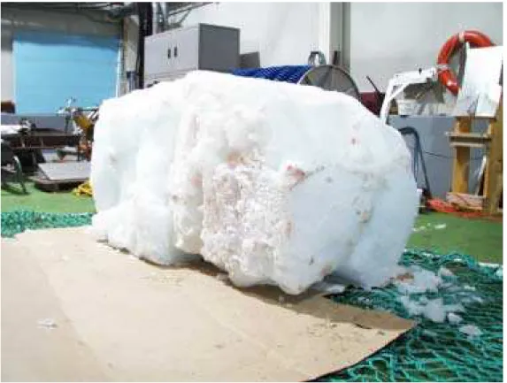
To create sample growlers large enough to induce the desired impact loads, two pieces of iceberg ice were fused together using artificial snow and chilled water as a welding agent. The two growlers produced were roughly parallelepiped shaped with initial principal particulars as follows: Length (m) Width (m) Height (m) Mass (kg) Growler #1 1.65 0.78 0.51 1324.5 Growler #2 2.0 0.66 0.94 1053.5
An effort was made to retain the dimensional integrity of the growlers during the test program by maintaining an Ice Tank water temperature of 0 °C and an air temperature from 0 to +2 °C although inevitably pieces of ice were broken off during impact and there was some melting. For this reason, the dimensions and weight of the growlers were recorded daily throughout the test program. A photograph of one of the growlers is presented in Figure 7.
Impact Apparatus Description
The impact apparatus was designed to be suspended in the tow carriage test bay. The unit consisted of a steel frame structure incorporating an instrumented impact plate (roughly 60 * 110 cm) that could be adjusted to an angle of 15, 30 or 45 degrees with respect to the longitudinal axis of the device representing the range of a vessel’s half angle of entrance (see Figure 8). One end of the apparatus includes a cylindrical enclosure, open at the bottom, that fills with water to increase the mass of the flooded unit to provide sufficient dynamic stability and inertia. The impact plate was supported by three tri-axial load cells used to measure orthogonal loads aligned in an impact plate based reference system. The instrumented plate also incorporates an innovative acrylic mechano-optical pressure measurement panel
(roughly 35 * 38 cm) calibrated to quantify the impact pressure and contact area using a high speed digital video camera to record the visual data during impact. During testing the test bay elevation was adjusted to a level that ensured good contact between the instrumented plate and the growler.
Working Principle and Design of the New Pressure Panel
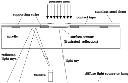
The working concept of the pressure panel is shown in Figure 9. The panel consisted of a thick slab of rigid transparent material, acrylic sheet (38cm x 38cm x 3.8cm), as shown in upper portion of the figure. The top sensing face of the panel was covered by a sheet of fairly thin stainless steel (1 mm in thickness). The steel sheet was supported by parallel strips of relatively incompressible tape (3mm width, ~0.25mm thick). Between these strips of tape were other slightly thinner strips of white tape (10mm width, ~0.15mm thick). When a concentrated load or pressure is applied to the top metal sheet it forces it to flex downward in the areas between the strips of thicker tape. This causes the white tape to flex downward, eventually making contact with the acrylic. Due to the spacing and width of the support strips a unit sensing area is effectively 13mm x 13mm. The degree of contact with the acrylic is proportional to the applied load.
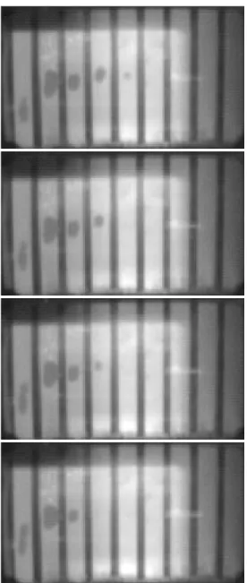
The amount of contact occurring when the white tape touches the acrylic is viewed from the opposite side of the acrylic slab employing the phenomenon of frustrated internal reflection. In the unloaded state, light from lamps illuminating the backside of the acrylic normally is partially internally reflected off the inside top surface of the acrylic and also off the surface of the white tape. However, wherever the tape makes contact with the acrylic slab the internal reflection becomes frustrated and also much less light is reflected off the surface of the tape. Hence, areas where contact occurs appear darker than the non-contact areas and one can then see exactly the contact regions. The amount of contact during an ice impact, and its variation with load, is recorded visually using a high speed video camera. Figure 10 shows some example images from the pressure panel acquired during a growler impact.
Growler Impact Tests
With the impact apparatus suspended in the tow carriage test bay at the desired elevation, the subject growler was positioned manually to ensure a good probability of contact with the moving instrumented panel. The test matrix for these experiments included:
• varying the tow carriage (collision) speed over a constant velocity range of 0.5 to 3.0 m/s;
• three growler planar orientations; and
• three impact plate angles with respect to the longitudinal axis of the apparatus.
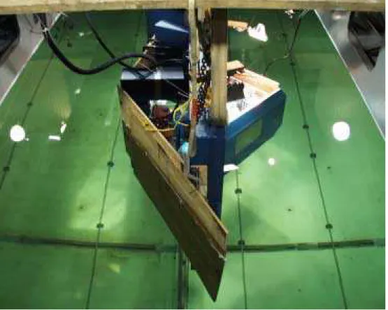
With the growler in position at the desired planar orientation, the tow carriage was accelerated to the specified constant velocity. Although targeting the impact plate was complicated by the influence of the bow wave generated by the impact apparatus on the growler position, with practice it was possible to achieve a quality impact for an acceptable proportion of the runs. At speeds greater than 0.75 m/s however, it proved necessary to fit plywood shields behind the impact plate to prevent turbulent flow induced bubbles from interfering with the field of view of the high speed video camera for the pressure panel measurements. See Figure 11. Extensive above water and underwater video recorded the growler movement leading up to and after impact.
A few experiments were conducted with the growler suspended in air as a pendulum with an arc length set to induce an impact velocity of 1 m/s. The impact plate was elevated above the water level with the angle fixed at 45 degrees for all these experiments. The only variable was the growler planar orientation – adjusted to one of three positions.
Thus a database of realistic ice induced structural impact data was collected using real iceberg ice under controlled conditions. A detailed description of the Ice Tank related experimental effort is provided in CUMMING et al (2000).
ICEBERG ICE PROPERTY EVALUATION
Complimenting the experimental program carried out in the IMD tanks, a research effort to evaluate the material properties of iceberg ice was completed in late 2000 to augment the relatively little data available in the open literature. Of particular relevance to the bergy bit/structure interaction research was the quantification of the strength of the iceberg ice at high strain-rates typical of collisions between ice and ships.
Ice Sample Preparation
Iceberg ice collected of Newfoundland’s north coast was stored in non-uniform blocks ranging in weight from 30 to 70 kg. The blocks were cut into slices 12 to 15 cm thick avoiding any obvious cracks and imperfections. Cylindrical samples, 10 cm in diameter and 25 cm in length, were then machined using a lathe in IMD’s Large Cold Room (LCR).
Experiments Carried Out
Ice Density: The density of each cylindrical sample was determined from its weight and dimensions.
Thick Section Analysis: Thick sections were cut from the ends of the cylinders to evaluate air bubble concentration and distribution from photographs. The air content of each sample was determined by comparing the density of the sample to the density of pure ice.
Thin Section Analysis: Thin sections were cut from each side of every block used in the tests, photographed, and analyzed for grain size distribution and diameter (Figure 12). The grain diameter was measured by counting the number of grain boundary intersections on the diameter of the thin section photograph.
Compression Tests: To quantify the compression strength of iceberg ice, uni-axial compression tests were carried out using MTS compression testing machines in IMD’s Large Cold Room on the cylindrical samples over a wide range of strain-rates from 10-8 to 10+1 s-1. Enough data was collected to derive compressive strength/strain-rate relationships.
COMPUTATIONAL HYDRODYNAMICS MODEL DESCRIPTION
The numerical simulations of the bergy bit/ship interactions are being developed using the following commercial software:
ANSYS (2000): A Finite Element (FE) program used to generate mesh for the geometry of the ship, bergy bits and water environment.
LS-DYNA: A program incorporating a computational fluid dynamics Navier-Stokes solver and a fluid/structure interaction component with capability to include the appropriate ice behaviour.
The postprocessor, LS-POST, was used to review and plot the results (a typical simulation is provided in Figure 13). The simulation work is ongoing.
FUTURE PLANS
All planned physical modeling related to this project has been completed and documented. The numerical simulation work of the bergy bit/ship interaction is just getting underway and will continue for a year or more. Future tasks for the project include the full scale bergy bit/ship impacts trial scheduled for the summer of 2001 on the Canadian Coast Guard heavy icebreaker CCGS ‘Terry Fox’. The vessel bow will be instrumented on the inside with an array of strain gages to measure hull strains during impacts so that finite element methods can be used to determine impact forces and pressures from
the strain data. As well, a scaled up version of IMD’s acrylic pressure panel design will be attached to the outside of the ship hull to measure pressure and contact area directly during impacts. The six degree of freedom ship motions will also be measured during impacts so that associated forces on the vessel can be estimated. Bergy bit characteristics including geometry and ice properties will also be determined. The data collected will provide essential full scale validation for the CH tools under development.
ACKNOWLEDGEMENTS
The authors would like to thank the National Research Council, the Program of Energy Research and Development (PERD), Mobil Oil Canada Properties, on behalf of the owners of the M/T Kometik Tanker, Petro-Canada, as Operator of Terra Nova, and the Regional Transportation Steering Committee (Representation from
Chevron Canada Resources Ltd., ExxonMobil Canada, Husky Oil Operations Ltd., Mosbacher Operations Ltd., Murphy Oil Company Ltd., Norsk Hydro Oil and Gas Canada Inc., Petro-Canada) for their financial support
of this research.
REFERENCES
Cumming D., Sears, M., Gagnon, R.E. (1998) “Physical Model Experiments to Assess the Hydrodynamic Interaction Between Iceberg Models and a Moored Offshore Structure – Phase 1”, IMD Report TR-1998-11.
Cumming, D., Georghiou, A., (1999) “Physical Model Experiments to Assess the Hydrodynamic Interaction Between Iceberg Models and a Floating Structure – Phase 2”, IMD Report TR-1999-08.
Cumming, D., Boone, K., Gagnon, R.E., (2000) “Description of Physical Model Experiments to Assess Growler Impact Loads”, IMD Report TR-2000-03. Murray, J.J. 1996. “Ice/Structure Interaction Laboratory and Numerical Modeling of Ice Berg Impact Summary and Progress Report”, IMD Report LM-1996-05.
Riche, T. 1999 “Design and Construction of Bergy Bit Iceberg Models and Tow Post”, IMD Report LM-1989-09.
Sullivan, M. 1997 “Optical Tracking at the Institute for Marine Dynamics”, Proc. Of the 4th Canadian Marine Hydrodynamics and Structures Conf., Ottawa, June 1997.
Wu, S. 1996. “Ice Mass-Floating Structures Interactions”, Contract Report: 31234-5-0025/01-XAQ, IMD Report CR-1996-04, Vol. 1&2.
Figure 1: Small and Medium Bergy Bit Models
Figure 3: Iceberg Model Towing Arrangement – Towing Tank Test Type #1
Figure 4: Small Iceberg Model with QUALYSIS Reflectors Fitted
Support Beams Spotlights Iceberg Model Restraining Post w/ Spring 3/8" Rope 1-1/2" Aluminum Tube Load Cell Tow Post Utility Carriage Main Tow Carriage View # 4 View # 3 Lateral Restraint Wires (4) 6.4 m
Figure 5: Test Set Up for Hydrodynamic Interaction between a Towed Ship Model on a Free-Floating Bergy Bit – Towing Tank Test Type #3
Figure 7: Growler used for Impact Experiments in Ice Tank
Figure 8: Impactor and Test Configuration for Growler Impact Experiments
Figure 9: Schematic illustrating the operating principle of the pressure panel. Thickness of the steel sheet and tape are exaggerated for presentation purposes.
Figure 10: Sequential images of a portion of the pressure panel showing an area of contact during a growler impact test. Because of the camera setup the images are compressed by about 50% in the vertical direction. The time interval between images is 1/500 s.
Figure 11: Impact Apparatus Fitted with Plywood Flow Shields