Publisher’s version / Version de l'éditeur:
Journal of Analytical Atomic Spectrometry, 16, 5, pp. 470-474, 2001
READ THESE TERMS AND CONDITIONS CAREFULLY BEFORE USING THIS WEBSITE. https://nrc-publications.canada.ca/eng/copyright
Vous avez des questions? Nous pouvons vous aider. Pour communiquer directement avec un auteur, consultez la première page de la revue dans laquelle son article a été publié afin de trouver ses coordonnées. Si vous n’arrivez pas à les repérer, communiquez avec nous à PublicationsArchive-ArchivesPublications@nrc-cnrc.gc.ca.
Questions? Contact the NRC Publications Archive team at
PublicationsArchive-ArchivesPublications@nrc-cnrc.gc.ca. If you wish to email the authors directly, please see the first page of the publication for their contact information.
NRC Publications Archive
Archives des publications du CNRC
This publication could be one of several versions: author’s original, accepted manuscript or the publisher’s version. / La version de cette publication peut être l’une des suivantes : la version prépublication de l’auteur, la version acceptée du manuscrit ou la version de l’éditeur.
For the publisher’s version, please access the DOI link below./ Pour consulter la version de l’éditeur, utilisez le lien DOI ci-dessous.
https://doi.org/10.1039/b100750p
Access and use of this website and the material on it are subject to the Terms and Conditions set forth at
Detection of volatile arsenic chloride species during hydride
generation: a new prospectus
Mester, Z.; Sturgeon, R.
https://publications-cnrc.canada.ca/fra/droits
L’accès à ce site Web et l’utilisation de son contenu sont assujettis aux conditions présentées dans le site LISEZ CES CONDITIONS ATTENTIVEMENT AVANT D’UTILISER CE SITE WEB.
NRC Publications Record / Notice d'Archives des publications de CNRC:
https://nrc-publications.canada.ca/eng/view/object/?id=b4fb31ec-3440-4c59-bade-71106ffb11d1
https://publications-cnrc.canada.ca/fra/voir/objet/?id=b4fb31ec-3440-4c59-bade-71106ffb11d1
Detection of volatile arsenic chloride species during hydride
generation: a new prospectus
Zolta´n Mester* and Ralph E. Sturgeon
Institute for National Measurement Standards, National Research Council of Canada, Ottawa, Ontario, Canada K1A 0R9. E-mail: zoltan.mester@nrc.ca
Received 22nd January 2001, Accepted 16th March 2001
First published as an Advance Article on the web 18th April 2001
Volatile inorganic- and organo-arsenic chloride species were detected following hydride generation. Arsenic trichloride can be formed and sampled from the headspace of arsenate or arsenite solutions following simple acidification to 2–8MHCl. Mono- and dimethylarsenic chloride species are formed during conventional hydride generation using sodium tetrahydroborate in a HCl medium. Increased HCl concentration in the sample solution promotes the formation of volatile chloride species in the hydride mixtures. The generated arsenic chloride species were characterized using electron impact ionization mass spectrometry.
Introduction
Hydride generation of arsenic, selenium, tin, antimony, etc. and, more recently, additional metals such as nickel, gold, etc.,1
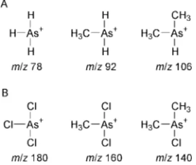
is one of the most widespread derivatization methods used in inorganic analytical chemistry.2 Although thousands of research papers have been published on the subject, the information available characterizing the various species generated during the process and the composition of the resulting hydride vapour is limited. Howard3recently reviewed the various hydride techniques used for trace element speciation. The arsenic hydrides typically considered include inorganic arsenic hydride (arsine), monomethylarsenic hydride (methylarsine) and dimethylarsenic hydride (dimethylarsine). Fig. 1 illustrates the structure of these arsines. Mester and Fodor4 examined the characteristics of the different arsenic species during their formation and atomization in a cool hydrogen diffusion flame atom source. Pergantis et al.5gained insight into the hydride formation process by the use of deuterium-labelled reagents. They also examined in detail the source of hydrogen in the analyte hydrides and possible exchange reactions between the hydrogen/deuterium present in the water or in the HCl and the hydrogen present in the system. It is widely known and discussed in the literature that volatile metal halides, such as arsenic chloride and fluoride, may be generated. The process is generally simple in that an acidified sample reacts with free halide ions in solution and the resulting metal halides are purged from the reaction mixture and detected. Lopez-Molinero et al.8 used a solution of sodium
fluoride in a sulfuric acid medium to generate volatile arsenic
trifluoride and also silicon tetrafluoride9 for analytical
purposes. The same group reported volatilization of AsIII following addition of a sodium chloride solution to sulfuric acid media.10The hydride and halide generation processes are
remarkably similar. Arsenic from an acidified sample can be directly purged out as arsenic chloride. If sodium tetrahy-droborate is also introduced into the same reaction system, hydride generation also occurs, but the two processes must be coexistent.
A decade ago, Tesfalidet and Irgum6,7
discussed the possibility of generating volatile AsCl3from arsenic solutions
simply by acidifying the sample solution and purging it with a suitable gas. They also confirmed, by differential-pulse polarography, that the resulting gaseous compound was arsenic trichloride and not arsine.
There is no discussion in the literature concerning the co-generation of hydrides and metal halides from strongly acidified solutions. Additionally, no information was found by the authors concerning the gas phase interaction of metal hydrides with acid vapours such as HCl or HF. In this paper, some results are presented concerning the formation of different chloride species arising from inorganic arsenic, monomethylarsenic and dimethylarsenic under typical hydride generation conditions using sodium tetrahydroborate. The experiments were achieved using static headspace sampling and solid phase microextraction sampling of hydride mixtures coupled to GC-ICP-MS and GC-EI-MS for detection.
Experimental
ReagentsAll chemicals used were of reagent grade unless otherwise stated. A 1000 mg l21stock solution of each of AsIII, DMA and
MMA NaBH4(Alfa Chemicals Inc., Newburyport, MA, USA)
was prepared by dissolving the appropriate salt in 1M hydrochloric acid. Note for future reference that inorganic arsenic (IAs) always refers to trivalent arsenic (AsIII). Solutions of NaBH4 (Alfa Chemicals Inc., Newburyport, MA, USA)
were prepared daily at a concentration of 8% (m/v), stabilized in 0.1% (m/v) NaOH (BDH Inc., Toronto, ON, Canada). Hydrochloric acid was prepared in-house by sub-boiling distillation of feedstock. High-purity de-ionised water (DDW, 18 MV cm), obtained from a NanoPure system (Barnstead/Thermolyne, Boston, MA, USA) fed with a reverse
Fig. 1 Structure of arsenic (A) hydrides and (B) chlorides. A, from left, arsine, methylarsine and dimethylarsine. B, from left, arsenic trichloride, methylarsenic chloride and dimethylarsenic chloride.
470 J. Anal. At. Spectrom., 2001, 16, 470–474 DOI: 10.1039/b100750p
osmosis supply line, was used for the preparation of all solutions.
100 ppm arsine gas in helium was purchased from Matheson, Ontario, Canada.
Instrumentation
A Perkin-Elmer SCIEX Elan 5000 inductively coupled plasma mass spectrometer was used for all elemental determinations. Evaluation of transient signals was performed using in-house software; peaks were integrated (typically 5–10 s) following the establishment of a baseline at extreme ends of the signal. A 75 mm thick polydimethylsiloxane–Carboxen coated SPME fiber was used for the sampling of volatile arsenic species. The fibers were conditioned and operated at temperatures specified by the manufacturer (Supelco, Bellefonte, PA, USA). The separation was performed using a Varian Star 3400 gas chromatograph and the experimental conditions used for the SPME-GC-ICP-MS are summarized in Table 1.
Gas chromatography-mass spectrometry experiments were performed using a HP 6890 GC and a HP 5973 electron impact ionization MSD system with ChemStation data collection and evaluation software package.
Batch hydride generation
Hydride generation and sampling were performed as follows: a 20 ml volume of acidified sample solution was placed in a septum-sealed 40 ml glass vial. The solution was vigorously stirred using a Teflon coated stir bar on a stirring plate. A 250 ml volume of 8% m/v sodium tetrahydroborate solution was injected through the septum into the stirred, closed vial using a plastic syringe. The septum was also fitted with a 22 gauge syringe needle which served as a ‘decompression vent’. The hydrides were sampled from the headspace of the vial with either a gas-tight syringe or with an SPME fiber. After the sampling period, the gas withdrawn by the syringe or adsorbed onto the SPME fiber was introduced into the GC unit. The glass vials were used only once and disposed of after each analysis. Because the thermal desorption step completely cleans the fiber, no additional clean up was necessary for SPME sampling. The practicality of this approach was confirmed by repeated blank extractions, wherein it was ascertained that no sample carry-over occurred using the current procedure. After each series of experiments, the stir bars were soaked overnight
in a 4M hydrochloric acid solution to ensure no carryover contamination. The analytical characteristics of the SPME procedure for hydride sampling has been fully discussed in our earlier work.17
Results
An analytical method has been developed for the determina-tion of inorganic arsenic (IAs), MMA and DMA based on batch hydride generation (HG), headspace sampling, GC separation and ICP-MS detection. The optimized conditions for the HG, sampling and determination are summarized in Table 1. All results were obtained using a multi-species synthetic standard solution (10–100 mg l21), 2Mhydrochloric
acid and a 0.3% sodium tetrahydroborate solution (effective concentration in the final sample solution). Fig. 2 shows a typical chromatogram of the IAs, MMA and DMA. It is evident that a clean separation of the three species has been achieved. The chromatographic separation of the hydride species was performed at room temperature. After the separation, the GC column was gradually heated up to 250 ‡C, starting from the third minute of the chromatographic run in order to clean the column. A significant amount of the total arsenic content was eluted from the column during this clean-up cycle, suggesting that the vapour phase above the arsenic mixture sampled by SPME or syringe contains additional species other than the three expected hydride species. For structural investigation of the unknown arsenic species, electron impact ionization mass spectrometry was used. The separation system described in Table 1 was coupled to the EI-MS. Applying the same (or very similar) separation conditions, a chromatogram of the three arsenic hydride species was generated. The mass spectrometer was operated in SCAN mode collecting data from m/z 40 to m/z 250, performing 4.1 full scans per second. As expected, an unknown peak was present in the chromatogram. Fig. 3 shows the separation of the 3 arsenic hydrides and the ‘unknown peak’
Table 1 Experimental conditions for HG-SPME-GC-ICP-MS ICP-MS
Rf power/W 800
Outer argon flow rate/l min21 15.0
Intermediate argon flow rate/l min21 1.7
Argon flow rate through the desorption unit/ml min21
35 Auxiliary argon flow rate/ml min21 350
Sampler/skimmer Nickel Data acquisition
Measurement mode Transient
Replicate time/ms 50
Dwell time/ms 50
Scan mode Peak hop
Number of replicates 1000 SPME
Fiber coating 75 mm PDMS–Carboxen
Extraction time/s 30
Extraction temperature/‡C 22 Thermal desorption temperature/‡C 200 GC T1/‡C 30 Hold time/min 3 Ramp 30 ‡C s21to 250 ‡C Column 30 m60.25 mm60.25 mm SPB-5
Fig. 2 GC-ICP-MS chromatogram of arsenic hydrides: 1, arsine; 2, methylarsine; 3, dimethylarsine. The corresponding solution phase concentration is 100, 10 and 5 ppb, respectively.
Fig. 3 GC-MS total ion chromatogram (scanningm/z 50Am/z 250) of
arsenic hydrides containing an ‘unknown peak’ (elution window: 1.5– 4 min). The sequence of elution of the arsenic hydrides can be found in Fig. 2.
J. Anal. At. Spectrom., 2001, 16, 470–474 471
Published on 18 April 2001. Downloaded by National Research Council Canada on 16/11/2015 20:47:25.
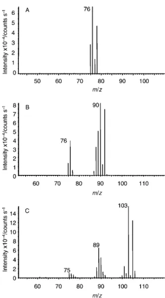
ranging from 1.5 to 4 min following the hydride peaks. Attempting a separation operating so close to the void volume of the system combined with EI-MS detection, the presence of additional peaks in the chromatogram is not very surprising. They may arise from water present in the sample or from many volatile impurities occasionally present in the sample introduction system or on the column itself which, when operated at low temperature, can serve as a very effective trap. The clear advantage of the EI-MS setup versus ICP-MS in this situation is that, although the ICP-MS is several orders of magnitude more sensitive, EI-MS can provide structural information. Fig. 1A shows the structure of the various arsenic hydride species. Fig. 4 shows the results of positive structural identification of the hydrides of IAs, MMA and DMA by electron impact mass spectrometry. The results are similar to those described by other authors.4,5 As noted earlier, the unknown peak detected with EI-MS may be a mixture of many components but probably mainly water. Positive identification of arsenic-containing molecules in this mixture is difficult because the monoisotopic arsenic does not offer a confirming characteristic isotopic pattern. Fig. 5 shows average mass spectra of the unknown peak. Although no intense m/z 75 peak is present in the spectra, which may indicate the presence of arsenic, the isotopic envelope of chlorine (m/z 35, 85%; m/z 37, 5%) can be clearly identified. There is a good possibility that the peak-pairs at m/z 110–112, 125–127, 140–142 and 145–147 arise from chlorine containing species. The masses identified as containing chlorine were extracted from the total ion
chromatogram and a single ion chromatogram was plotted. Interrogating the mass spectra of these chlorine-containing peaks permitted the clear identification of the presence of chlorine-containing arsenic compounds. The structures of the identified arsenic chloride species are shown in Fig. 1B.
The next step was the modification of the existing separation scheme to allow the separation of the chloride species of IAs, MMA and DMA. Fig. 6 shows a chromatogram of the three chloride species and Fig. 7 shows their mass spectra. The chromatographic column and the injector conditions were the same as presented in Table 1. After 1 min hold the temperature ramped from 130 ‡C to 270 ‡C at 20 ‡C min21. Table 2
summarizes the identification of the fragment ions arising from AsCl3, AsMeCl2and AsMe2Cl.
Following identification of the described species, the question arises as to their origin and whether they are present in the hydride mixture or are artifacts created during the sampling or separation process. It should be noted that the
Fig. 4 Electron impact mass spectra of: A, arsine; B, methylarsine; C, dimethylarsine.
Fig. 5 Average mass spectra of the unknown peak presented in Fig. 3.
Fig. 6 GC-MS total ion chromatogram of: 1, arsenic trichloride; 2, methylarsenic chloride; 3, dimethylarsenic chloride.
Table 2 MS peak identification table of volatile arsenochloride species
Species m/z Arsenic trichloride [As]z 75 [AsCl]z 110 [AsCl2] z 145 [AsCl3] za 180 Monomethylarsenic dichloride [As]z 75 [AsCl]z 110 [AsCl2] z 145 [AsCH3] z 90 [CH3AsCl] z 125 [CH3AsCl2] za 160 Dimethylarsenic chloride [As]z 75 [AsCl]z 110 [AsCH3] z 90 [CH3AsCl] z 125 [As(CH3)2] z 105 [(CH3)2AsCl] za 140
aParent molecular ion.
‘unknown’ peak was observed with ICP-MS experiments using both gas injection with a syringe and SPME sampling of the generated hydride mixture. Therefore, there is a good possibility that the chloride species arise independently of the sample introduction method. Artifact formation of the species during the chromatographic process cannot be ruled out at this point, but it would be rather unlikely because of the relatively high stability of arsenic hydride species in an inert helium atmosphere (which is the carrier gas used for the GC experiments).
An experiment was run wherein the headspace above an AsIII solution acidified with 6M HCl was sampled using a carbon SPME fiber. At room temperature, AsCl3was clearly identified
in the vapour phase, which suggests that formation of AsCl3
can occur in the condensed phase. The test was repeated with a pentavalent arsenic solution with the same qualitative result. The same experiment was then conducted with DMA and MMA. No MMA or DMA chloride species were detected in the headspace, suggesting that the formation of DMA and MMA chloride species also requires the presence of a strong reducting agent, such as sodium tetrahydroborate.
To study the tendency of chloride species formation during the hydride generation process, a series of experiments was run using HCl concentrations ranging from 1 to 9M. As suspected, increasing HCl concentration in the hydride mixture clearly increased the level of chloride species, and decreased the level of hydrides.
Condensed phase formation of arsenic chloride was clearly demonstrated above. The gas phase transformation of AsH3
into AsCl3was studied using a sample of 100 ppm v/v arsine
gas in helium contained in a 40 ml gas-tight vial into which was injected 1 ml of HCl vapour (collected above concentrated HCl solution) using a syringe. Sampling the vial before introduction of HCl provided a clear spectrum of AsH3. However, after the
introduction of HCl vapour, AsCl3 was detected in the gas
phase by EI-MS.
These observations strongly suggest that hydride generation of arsenic species also generates the chloro- forms of the arsenic species. It must be emphasized that the results obtained refer to batch hydride generation conditions, which likely favour the slow kinetics of evaporation of the semi-volatile arsenic chloride species.
Contact of arsine with HCl vapour can also result in formation of arsenic chloride. Naturally, in a purged, flow-through system, the contact time of the hydride vapour with the HCl vapour can be much shorter than under batch conditions studied here and the exchange reaction may be less pronounced. The decreased efficiency of hydride generation at high HCl concentrations may be the result of a shift in the production of the hydride species to the chloride form. This naturally represents completely different transport efficiencies and differences in atomization characteristics (which can be quite pronounced in ‘cold’ atomization sources).
The above results are entirely qualitative at this point as it was difficult to quantify the ratio of the chloro- and hydride species. However, in light of these results, some of the theories relating to the hydride generation process should be revisited as all are based on the presumption that the gaseous metallic product arising from the gas–liquid separator is that of the hydride. As an example, the observation made by Welz and Schubert-Jacobs,11as well as several other researchers,12,13that use of increased HCl concentration during hydride generation can decrease transition metal interferences may have an alternative explanation. The accepted explanation for this phenomenon is the increased solubility of the transition metal precipitates in the strongly acidic environment inhibiting the absorption of hydrogen or the formed metal hydrides with their subsequent decomposition on the metallic surface. However, a plausible alternative explanation may also be based on a shift in the formation of hydride to chloride (perhaps arsine to arsenic trichloride) in a 5MHCl medium. Arsenic chloride formation is fundamentally free from classical transition metal interfer-ences. Ellis et al.14 studied the effect of NaCl on hydride generation efficiency and concluded that the increased salt concentration had a positive effect on the signal intensity of arsenic and selenium hydrides. Their explanation was based on the ‘salting out’ effect, to account for an improved gas–liquid separation efficiency. These observations may also lead to an alternative explanation via the enhanced formation of metal chloride species in mixtures containing high NaCl concentra-tions. Formation of volatile metal chloride species in high-salinity environments has already been reported for sampling methylmercury chloride,15 and several organotin chloride16 species have been sampled from the vapour phase of a saturated salt solution.
A better understanding of the formation of volatile chloride and fluoride species of mercury, tin, arsenic, germanium, etc., will help to improve or tailor the hydride generation process better for actual analytical use.
References
1 A. S. Luna, R. E. Sturgeon and R. C. de Campos, Anal. Chem., 2000, 72, 3523.
2 J. Dedina and D. L. Tsalev, Hydride Generation Atomic Absorption
Spectrometry, Wiley, New York, 1995.
3 A. G. Howard, J. Anal. At. Spectrom., 1997, 12, 267. Fig. 7 Electron impact mass spectra of: A, arsenic trichloride; B,
methylarsenic chloride; C, dimethylarsenic chloride.
J. Anal. At. Spectrom., 2001, 16, 470–474 473
Published on 18 April 2001. Downloaded by National Research Council Canada on 16/11/2015 20:47:25.
4 Z. Mester and P. Fodor, Spectrochim. Acta, Part B, 1997, 52, 1763. 5 S. A. Pergantis, W. Winnik, E. M. Heithmar and W. R. Cullen,
Talanta, 1997, 44, 1941.
6 S. Tesfalidet and K. Irgum, Anal. Chem., 1988, 60, 2031. 7 S. Tesfalidet and K. Irgum, Fresenius’ J. Anal. Chem., 1990, 338,
741.
8 A. Lopez-Molinero, M. Benito, Y. Aznar, A. Villareal and J. R. Castillo, J. Anal. At. Spectrom., 1998, 13, 215.
9 A. L. Molinero, A. Morales, A. Villareal and J. R. Castillo,
Fresenius’ J. Anal. Chem., 1997, 358, 599.
10 A. Lopez-Molinero, J. R. Castillo, P. C. Pascual and A. Callizo,
Microchim. Acta, 1999, 131, 225.
11 B. Welz and M. Schubert-Jacobs, J. Anal. At. Spectrom., 1986, 1, 23. 12 Y. An, S. N. Willie and R. E. Sturgeon, Spectrochim. Acta, Part B,
1992, 47, 1403.
13 J. W. Hershey and P. N. Keliher, Spectrochim. Acta B, 1986, 41, 713.
14 R. I. Ellis, N. G. Sundin, J. F. Tyson, S. A. McIntosh, C. P. Hanna and G. Carnrick, Analyst, 1998, 123, 1697.
15 Z. Mester, J. Lam, R. Sturgeon and J. Pawliszyn, J. Anal. At.
Spectrom., 2000, 15, 837.
16 Z. Mester and R. E. Sturgeon, unpublished data, 2000. 17 Z. Mester, J. Lam and R. Sturgeon, J. Anal. At. Spectrom., 2000,
15, 1461.