IN A PILOT-SCALE FURNACE
by
SHIN-WON KANG
B.S., Mechanical Engineering Seoul National University
(1979)
S.M., Mechanical Engineering Massachusetts Institute of Technology
(1984)
SUBMITTED TO THE DEPARTMENT OF MECHANICAL ENGINEERING IN PARTIAL FULFILLMENT OF THE REQUIREMENTS FOR THE
DEGREE OF DOCTOR OF PHILOSOPHY
at the
MASSACHUSETTS INSTITUTE OF TECHNOLOGY December 1987
@ Massachusetts Institute of Technology
Signature of Author
Certified by
Certified by
Accepted by
Department of Mechanical -Engineeri4, December 1987
Professor Jdnos M. Bedr, Thesis Supervisor
A
.
,i
Professor AdelF. S , Thesis Supervisor
Professor Ain A. Sonin Chairman, Departmental Committee on Graduate Students h X
S
epartment of Mechanical EngineeringOF TECHWOLOGY
MAR
18 1988
COMBUSTION AND ATOMIZATION STUDIES OF COAL-WATER FUEL IN A LAMINAR FLOW REACTOR AND
IN A PILOT-SCALE FURNACE by
SHIN-WON KANG
Submitted to the Department of Mechanical Engineering in December 1987 in partial fulfillment of the requirements for the Degree of Doctor of Philosophy in
Mechanical Engineering
ABSTRACT
The thesis is composed of two separate but related topics which are discussed separately in Part 1 and Part 2.
PART 1: "Fundamental Study of Coal-Water Fuel Droplet Combustion
in a Laminar Flow Reactor"
The processes of devolatilization and char burnout were studied in a laminar flow reactor (LFR) by two experimental procedures. In the first of these, a coal-water fuel (CWF) droplet generator was developed and used to feed CWF droplets directly into the LFR. The CWF droplet generator, which consisted of a twin-fluid, internally mixed atomizer and
a series of skimmers to reduce the feed rate of CWF droplets into the LFR, was capable of producing CWF droplets in the size range of 5-500
micrometers at feed rates of less than 3 mg/sec.
In the second parallel study, solid samples withdrawn from a CWF spray flame, close to the atomizing nozzle, were size graded and fed into the LFR in low particle concentrations. Their combustion history in the LFR was determined by the use of high-speed cinematography and by monitoring the intensity of radiation emitted by individual CWF ag-glomerate during combustion (by fiber optic radiometry).
The Part 1 study has established the importance of rotation induced by the volatile evolution on the breakup of coal-aggregates and the release of ash particles. The centrifugal force due to particle rotation
promotes the separation of both weakly adhering coal particles and char
fragments during devolatilization and char burnout.
The results show that there is competition between centrifugal force
which favors the breakup of coal-aggregates and adhesive force between coal particles during the plastic stage of coal pyrolysis. Based upon the theoretical model of agglomeration, the adhesive force on the process
of coalescence of-coal particles is strongly dependent on the duration of the plasticity of coal particles. It is also found that rapid heating
reduces the tendency of coal particles to form aggregates during the CWF droplet evaporation. Therefore, whether coal particles burn individually or as aggregates can be influenced by the time-temperature history of the CWF agglomerate and hence by burner design.
PART 2: "(Flash-) Atomization and Combustion Studies of Coal-Water Fuel in a Spray Test Facility and in a Pilot-Scale Furnace" During CWF droplet combustion, coal particles tend to agglomerate within CWF droplets. Hence, the resulting coal particle size
distribution (p.s.d.) is determined more by the p.s.d. of the atomized
fuel spray than by the initial p.s.d. of the coal particles. Therefore, the atomization quality, (i.e., fineness of CWF spray droplets), is considered to be the most important variable affecting the combustion
quality of CWF combustion including: ignition, carbon burnout, and the
resultant fly-ash particle size.
In the Part 2 study, the atomization quality of CWF was investigated
in a Spray Test Facility (STF) equipped with a laser diffraction spray
analyzer. A capillary viscometer was also developed to measure a
viscosity of CWF at high shear rate. The viscosity of CWF was found to be dependent upon shear rate (i.e., non-Newtonian fluid), and the
atomization quality of CWF was correlated with rheological properties of CWF.
Convective tube bank erosion due to impaction of fly-ash particles could be reduced if the fly-ash particles were sufficiently small; such
particles would follow the gas streamlines around tubes rather than impact on them. A finer p.s.d. of CWF droplets, and thus, a finer fly-ash p.s.d. could be obtained by the use of fuel treatments which induced flash-atomization.
The theoretical models of CWF flash-atomization and spray angle
change due to flash-atomization were also developed and discussed. The
experimental results of CWF flash-atomization in the STF and in a
pilot-scale furnace show that a thermally assisted atomization of CWF sig-nificantly improves the quality of CWF droplets p.s.d., and thereby,
flame stability, carbon conversion efficiency, and reduction of fly-ash
p.s.d.
Thesis Supervisors:
Jdnos M. Be6r, Professor of Chemical and Fuel Engineering Adel F. Sarofim, Professor of Chemical Engineering
DEDICATION
This thesis is dedicated to my parents, my grandmother,
my daughter So-Yeun (Janet R.) and my wife Kyung-Hee.
ACKNOWLEDGEMENTS
I would like to express my deepest appreciation to Professor Jdnos M. Be6r, who introduced me to the field of combustion, and to Professor Adel F. Sarofim, my co-supervisor. During my doctoral program at M.I.T.
they supported and guided me enthusiastically through many difficult
times and were always accessible and patient.
I would also like to thank Professor Peter Griffith for being the chairman of my thesis committee. As thesis supervisor of my master
program and as chairman of my doctoral thesis committee, Professor
Griffith was a vital resource for me during my stay at M.I.T.
I am also deeply grateful to Dr. T.-U. Yu, Dr. D. Froelich, Dr. J.D. Teare, Dr. S.-C. Rah, Mr. L.D. Timothy, Mr. D.B. Jones, Dr. M.A. Toqan, Dr. S. Srinivasachar, and Dr. P.M. Walsh for their valuable discussions and help throughout my research.
My younger brother, Shin-Gyoo Kang, who is a doctoral student in the Department of Chemical Engineering at M.I.T., made himself indispensable
to me both in the computer work and in the laboratory.
I also extend my deepest appreciation to Mr. P. Dozois and Mr. F. Woodworth in the Nuclear Machine Shop for their great help in making the apparatus, and to the technical staffs, Mr. D.E. Bash, Mr. W.T. Mason, and Mr. M.A. James for their continuous help in the experimental work in
the M.I.T. Combustion Research Facility. My special thanks go to Ms. B.
Caputo for typing the thesis manuscript with patience.
Financial support of this research work from the U.S. Department of
Energy under Grant Number DE-FG22-84PC70268 is gratefully acknowledged.
Finally, I wish to thank my family, my family-in-law, and my wife
TABLE OF CONTENTS ABSTRACT ... ACKNOWLEDGEMENTS ... TABLE OF CONTENTS ... Part 1: "Fundamental in a Laminar LIST OF FIGURES ... LIST OF TABLES ... NOMENCLATURE ... CHAPTER 1.1 1.2 ,tudy Flow ... ... ... of Coal-Water Reactor" ... ... ... ... 1. INTRODUCTION ... Introduction ... Objectives of Investigat.on
CHAPTER 2. EXPERIMENTAL INVESTIGATION ...
2.1 Introduction ...
2.2 Experimental Apparatus for CWF Drop
2.2.1 CWF Droplet Generator ... 2.2.2 Atomizer ...
2.2.3 Laminar Flow Reactor ... 2.2.4 Feeding Probe ...
2.2.5 Sample Collection Probe .... 2.2.6 Fuel Supply Tank ...
2.2.7 Photographic Recording System e
2.3 Experimental Apparatus for CWF Agglo 2.3.1 Laminar Flow Reactor ...
. . . . ... t Inj ec tion ... . . ... ... ... ... ... ... ... merate Injection.. ...
Fue Drop let Combusti on
Pag-e 2 5 6 12 13 18 19 26 26 28 30 30 30 33 36 40 43 46 46 46 47 47
2.3.2
2.3.3
2.3.4
Solid-Sample Feeding System ... Collection Probe ...
Fiber Optic Radiometer ...
CHAPTER 3. EXPERIMENTAL OBSERVATIONS OF CWF DROPLET COMBUSTION ...
3.1 Introduction ... 3 .2 Ign ition ... 3.3 Volatile Combustion ... 3.4 Particle Rotation ... 3.5 Ignition of Char ... 3.6 Char Burnout ... 3.7 Fragmentation ...
CHAPTER 4. THEORETICAL MODELS .. 4.1 Model of Particle Rotation
4.1.1 Introduction ...
4.2
4.1.2 Derivation of Angular Velocity of Rotating CWF Agglomerate ...
4.1.3 Angular Velocity of Rotating CWF Agglomerate f Isothermal Devolatilization Process ... 4.1.4 Geometrical Factor of Devolatilization Pores 4.1.5 Centrifugal Force Induced by Particle Rotation
Model of Particle Agglomeration... 4.2.1 Introduction ...
4.2.2 Plasticity of Bituminous Coal ... 4.2.3 Contact Area during Particle Agglomeration 4.2.4 Adhesive Force during Particle Agglomeration
or 50 50 53 54 54 58 58 60 63 65 65 70 70 70 70 an 77 79 93 95 95 95 100 103 103 4.2.4.1 Surface Tension Force ...
... ... ...
4.2.4.2 Adhesive Force due to Coke Interconnection ... 103
4.2.4.3 Adhesive Force during Particle Agglomeration ... 107
4.3 Time-Temperature History of CWF Agglomerate ... 107
4.3.1 Introduction ... ... 107
4.3.2 Particle Heating Rate in Pre-Evaporation Stage ... 108
4.3.3 Particle Heating Rate in Evaporation Stage ... 111
4.3.4 Particle Heating Rate in Heat-Up Stage ... 112
4.3.5 Particle Heating Rate during Devolatilization ... 113
4.3.6 Particle Heating Rate during Char Burnout ... 117
CHAPTER 5. RESULTS AND DISCUSSIONS ... 121
5.1 Particle Rotation ... ... 121
5.1.1 Model Predictions of Particle Rotation ... 121
5.1.2 Results of Statistical Study of Particle Rotation .... 128
5.2 Adhesive Force during Particle Agglomeration ... 135
5.3 Comparison of Centrifugal Force with Adhesive Force ... 143
CHAPTER 6. CONCLUSIONS ... 146
REFERENCES ... 148
APPENDICES ... 151
APPENDIX A GEOMETRICAL FACTOR OF DEVOLATILIZATION PORES WITH GAVALAS' PORE MODEL .. ... 152
A.1 Derivation of Geometrical Factor .. ... 152
A.2 Application of Gavalas' Model to Geometrical Factor ... 158
APPENDIX C COMPUTER PROGRAMS ...
C.1 Computer Program for Model of Particle Rotation ... C.2 Computer Program for Model of Particle Agglomeration C.3 Computer Program for Calculation of Geometrical Factor
Part 2: "(Flash-) Atomization and Combustion Studies of Coal-Water Fuel in a Spray Test Facility and in a Pilot-Scale Furnace" TABLE OF CONTENTS ... LIST OF FIGURES ... LIST OF TABLES ... NOMENCLATURE ... CHAPTER 1.1 1.2 1. INTRODUCTION ... Introduction ... Objectives of Investigation
CHAPTER 2 EXPERIMENTA TNN TTnATTn
2.1 Experimental Apparatus for CWF Atomization 2.1.1 Spray Test Facility ...
2.1.2 Laser Diffraction Spray Analyzer ... 2.1.3 Atomizer ...
2.1.4 Capillary Tube Viscometer ... 2.1.5 Fuel Treatment Systems ...
2.2 Experimental Apparatus for CWF Combustion
2.2.1
2.2.2
S tudy
Study Combustion Research Facility ...
Water-Quench Sampling Probe ...
164 164 166 172 . ... . . .. . ... . . . .. . . ... . .. . ... 173 174 177 181 182 185 185 186 187 187 187 190 192 192 195 197 197 202
2.2.3 Steam-Heated Sampling Probe ... 202
CHAPTER 3. ATOMIZATION STUDY OF CWF .. ... 209
3.1 Introduction ... ... 209
3.2 Atomization Mechanism in Twin-Fluid Atomizer ... 211
3.3 Representative Shear Rate during CWF Atomization ... 213
3.4 Experimental Results of Spray Droplet Size with CWF Viscosity ... ... 220
3.5 Correlation of CWF Atomization .. ... 231
3.5.1 Basic Form of Atomization Correlation ... 231
3.5.2 Atomization Correlation for OR-KVB Atomizer ... 233
3 .6 Summary ... 239
CHAPTER 4. FLASH-ATOMIZATION STUDY OF CWF ... 243
4.1 Introduction ... ... 243
4.2 Theoretical Models of CWF Flash-Atomization ... 244
4.2.1 Nucleation Sites in Coal Particle during CWF Flash-Atomization .. ... 244
4.2.2 Mechanism of CWF Flash-Atomization ... 245
4.2.3 Bubble Growth Dynamics ... 249
4.2.4 Effect of Superheat on CWF Flash-Atomization ... 255
4.2.5 Spray Angle Change during Flash-Atomization ... 258
4.3 Experimental Results of CWF Flash-Atomization and Discussions ... 264
4.4 Experimental Results and Correlation of Spray Angle Change during Flash-Atomization .. ... 270
CHAPTER 5. COMBUSTION STUDY OF CWF WITH FUEL TREATMENTS ... 278
5.1 Introduction ... ... 278
5.3 Summary ... CHAPTER 6. REFERENCES APPENDICES APPENDIX A APPENDIX B APPENDIX C CONCLUSIONS ... . . . . 30 3
PRINCIPLE OF LASER DIFFRACTION SPRAY ANALYZER ... 304 PRINCIPLE OF CAPILLARY TUBE VISCOMETER ... 307 EXPERIMENTAL DATA OF IN-FLAME MEASUREMENTS ... 310
BIOGRAPHICAL NOTE ...
294
298
300
PART 1
FUNDAMENTAL STUDY OF COAL-WATER FUEL DROPLET COMBUSTION IN A LAMINAR FLOW REACTOR
LIST OF FIGURES
Figure Page
1 Schematic Diagram of Experimental Apparatus
(CWF Droplet Injection) ... 31
2 Photograph of Experimental Apparatus
(CWF Droplet Injection) ... 32 3 Schematic Diagram of CWF Droplet Generator ... 34 4 Photographs of CWF Droplet Generator
(a) Assembled, (b) Disassembled ... ... 35 5 Schematic Diagram of Twin-Fluid Atomizer ... 37 6 Photographs of Twin-Fluid Atomizer
(a) Assembled, (b) Disassembled ... ... 38 7 Schematic Diagram of Spray Test Facility and
Laser Diffraction Spray Analyzer ... ... 39
8 Schematic Diagram of Laminar Flow Reactor
(CWF Droplet Injectior) ... 41
9 Schematic Diagram of Furnace Casing Gas Flow ... 42 10 Schematic Diagram of Furnace Elevating
Support System .... ... 44
11 Schematic Diagram of Feeding Probe
(CWF Droplet Injection) ... 45 12 Schematic Diagram of Sample Collection Probe
(CWF Droplet Injection) ... 45 13 Schematic Diagram of Experimental Apparatus
(CWF Agglomerate Injection) ... 48
14 Schematic Diagram of Laminar Flow Reactor
(CWF Agglomerate Injection) ... 49
15 Schematic Diagram of Solid-Sample Feeding System ... 51 16 Schematic Diagram of Sample Collection Probe
(CWF Agglomerate Injection) ... 52 17 Mechanism of CWF Droplet Combustion ... 55
18 Sequential Photographs from High-Speed Cinematographs of CWF Droplet Combustion (Agglomerate Diameter
= 150 pm, Furnace Gas Temperature = 1100 K,
Oxygen Partial Pressure - 100 %) ... 56 19 Sequential Photographs from High-Speed Cinematographs
of CWF Droplet Combustion (Agglomerate Diameter = 200 pm, Furnace Gas Temperature - 1100 K,
Oxygen Partial Pressure = 100 %) ... 57 20 Sequential Photographs from High-Speed Cinematographs
of CWF Droplet Combustion; Localized Ignition Followed by Spread of Ignition (Agglomerate Diameter - 100 pm in Figure A and 130 pm in Figure B, Furnace Gas Temperature = 1100 K,
Oxygen Partial Pressure - 100 %) ... 59 21 Sequential Photographs from High-Speed Cinematographs
of CWF Droplet Combustion; Soot Clouds and Soot Trails (Agglomerate Diameter - 50-200 pm, Furnace Gas
Temperature = 1200 K, Oxygen Partial Pressure = 20 %) .... 61 22 Sequential Photographs from High-Speed Cinematographs
of CWF Droplet Combustion; Soot Clouds and Soot Trails (Agglomerate Diameter - 150 pm, Furnace Gas
Temperature = 1200 K, Oxygen Partial Pressure = 20 %) .... 62 23 Radiation Intensity Traces of Rotating CWF Agglomerate
(Agglomerate Diameter = 100 pm, Furnace Gas Temperature = 1750 K, Oxygen Partial Pressure - 100 %)
(a) 800 cycles/sec, (b) 1400 cycles/sec,
(c) 2800 cycles/sec .... ... 64 24 Sequential Photographs from High-Speed Cinematographs
of CWF Droplet Combustion; Fragmentation during Char Burnout (Agglomerate Diameter - 160-180 pm, Furnace Gas
Temperature = 1400 K, Oxygen Partial Pressure = 100 %) ... 66 25 Radiation Intensity Traces of Burning CWF
Agglomerate; Fragmentation during Char Burnout ... 67 26 Schematic Diagram of Rotating CWF Agglomerate ... 72 27 Scanning Electron Micrographs of CWF Agglomerates ... 81 28 Distribution of Devolatilization Pores on
Outer Surface of CWF Agglomerate ... ... 82
N
Z coso.Icos4I|
29 i-1 versus Total Number of Pores N ... 86 N
30 Typical Pore Size Distribution of 100 Largest Macropores . 88 31 Probability Density Distribution of Geometrical Factor ... 89 32 Configuration of Rotating Sphere with One Pore ... 91 33 Configuration of Spherical Coordinates ... 92 34 Force Balance during CWF Agglomerate Rotation ... 94 35 Surface Tension Force at Neck Region of Two
Coalescent Coal Particles in CWF Agglomerate ... 104 36 Agglomeration Process of Coal Particles in
CWF Agglomerate ... ... 105 37 Typical Time-Temperature History of CWF Agglomerate
during CWF Combustion ... ... 109 38 Predictions of Angular Velocity of Rotating
CWF Agglomerate; Effect of Oxygen Partial Pressure (Agglomerate Diameter - 100 pm, Furnace Gas Temperature = 1100 K)
(a) 20 % 02, (b) 40 % 02, (c) 100 % 02 -.-... 122 39 Predictions of Angular Velocity of Rotating
CWF Agglomerate; Effect of Furnace Gas Temperature (Agglomerate Diameter = 100 pm, Oxygen Partial Pressure = 20 %) (a) 1100 K,
(b) 1400 K, (c) 1750 K ... ... 123 40 Predictions of Angular Velocity of Rotating
CWF Agglomerate; Effect of Agglomerate Diameter (Furnace Gas Temperature = 1400 K, Oxygen Partial
Pressure = 20 %) (a) 200 pm, (b) 100 pm, (c) 60 pm ... 124 41 Predictions of Angular Velocity of Rotating CWF
Agglomerate; Effect of Agglomerate Diametef
(Devolatilization Rate Constant = 950 sec )... 125 42 Comparison between Prediction and Experimental
Data of Angular Velocity of Rotating CWF Agglomerate ... 126 43 Predictions of Centrifugal Force; Effect of
Furnace Gas Temperature on Centrifugal Force (Agglomerate Diameter = 100 pm, Oxygen Partial
44 Probability Density Distributions of Angular Velocities; Effect of Oxygen Partial Pressure
(Agglomerate Diameter = 90-106 pm, Furnace Gas Temperature - 1750 K) (a) 20 % 02, (b) 40 % 02,
(c) 70 % 02, (d) 100 % 02 -... 45 Probability Density Distributions of Angular
Velocities; Effect of Oxygen Partial Pressure (Agglomerate Diameter - 90-106 pm, Furnace Gas Temperature - 1400 K) (a) 40 % 02, (b) 70 % 02,
(c) 100 % 02
---46 Probability Density Distributions of Angular Velocities; Effect of Furnace Gas Temperature
(Agglomerate Diameter - 90-106 ym, Oxygen
Partial Pressure - 100%) (a) 1100 K, (b) 1250K, (c) 1400 K, (d) 1750 K ...
47 Probability Density Distributions of Angular Velocities; Effect of Agglomerate Diameter
(Furnace Gas Temperature - 1400 K, Oxygen Partial Pressure - 100%) (a) 212-250 pm,
(b) 150-180 pm, (c) 90-106 pm, (d) 45-53 pm ... 48 Predictions of C, L, E, Normalized A, F , F and
Adhesive F rce F A versus Time for Partile heating Rate of 10 K/sec ...
49 Predictions of C, L, E, Normalized A, F , F , and Adhesive Fgrce FA versus Time for Partiale heating Rate of 10 K/sec ...
50 Comparisons of C, L, E, Normalized A, and Adhesive Force FA versgs Time for Diffgrent Particle Heating Rates (a) 10 K/sec, (b) 10 K/sec ... 51 Predictions of C, L, E, Normalized A, and Adhesive
Force F versus Time for Different Furnace Gas Temperature (Agglomerate Diameter = 100 pm, Oxygen Partial Pressure = 20 %)
(a) 1100 K, (b) 1750 K ...
52 Predictions of C, L, E, Normalized A, and Adhesive Force FA versus Time for Different Agglomerate Diameter (Furnace Gas Temperature - 1400 K, Oxygen Partial Pressure = 20 %)
(a) 200 pm , (b) 60 pm ...
53 Predictions of C, L, E, Normalized A, and Adhesive Force FA versus Time for Different Oxygen Partial Pressure (Agglomerate Diameter - 100 pm, Furnace Gas Temperature = 1100 K) (a) 20 % 02, (b) 100 % 0
... 139 ... 140 2 - 141 ...-.-... 130 -.-. -... 131 ... 132 133 136 137 138
54 Comparisons of Adhesive Force FA with Centrifugal
Force F . for Different Furnace Gas
Temperagurtigglomerate Diameter = 100 pm, Oxygen
Partial Pressure - 20 %) (a) 1100 K, (b) 1750 K ... 144 B.l. Mass Mean Diameter of Spray Droplet at Various AFRs ... 163
LIST OF TABLES
Table
1 Example of Typical Pore Size Distribution of the 100 Largest Pores on the Outer Surface of
NOMENCLATURE
A contact area
--
)
growth rate of contact area LdtjA. cross-sectional exit area of devolatilization pore
1
Z A. total cross-sectional exit area of devolatilization pores
A surface in eqs. (3) and (4)
A .. .AN average cross-sectional exit area of devolatilization pores for each pore group in eq. (23)
B number of moles of combustion product per mole of oxygen in eq. (83)
B ,B2 constant in eq. (71)
cs control surface
cv control volume
mass fraction of unreacted coal
C. initial mass fraction of unreacted coal (= 1-f ) C volume fraction of unreacted coal
cp specific heat of CWF droplet/agglomerate c vol specific heat of volatiles
DO02 diffusion coefficient of oxygen
D p diameter of coal particle in eq. (A-15) DI. D pore diameter for each pore group
d diameter of CWF droplet/agglomerate p
Z
mass fraction of coke-residue (char) E volume fraction of coke-residue (char)Eth threshold volume fraction of coke-residue (char) 1-
]
-a 2
EI, E2 activation energy
FA adhesive force between two coalescent coal particles Fcentrif centrifugal force acting on a coal particle
FE adhesive force due to coke interconnection
FEl adhesive force due to coke interconnection in stage 1 FE2 adhesive force due to coke interconnection in stage 2 FE3 adhesive force due to coke interconnection in stage 3 F surface tension force due to liquid metaplast
f mass fraction of ash (mineral matter) a
f volume fraction of ash (mineral matter)
f .. fN fraction of volatile mass per total volatile mass loss for each pore group
*
f fraction of volatile mass in eq. (A-15)
G acceleration of gravity
AHchar heat of combustion of coal surface AHdevol endothermic heat of devolatilization
AHVol heat of combustion of volatiles k devolatilization rate constant
kg rate constant in eq. (29)
ky rate constant in eq. (30)
kyk 2 Arrehnius type reaction rate
k thermal conductivity of surrounding gas g
kvol thermal conductivity of volatiles L mass fraction of liquid metaplast
L volume fraction of liquid metaplast
L mass fraction of solid metaplast initially existing in coal
L latent heat of evaporation W
2eff effective circumference
MF frictional moment of rotating CWF agglomerate M0 original mass of CWF agglomerate
z M sum of moments about origin mc mass of coal particle
m mass of CWF droplet/agglomerate SVol rate of volatile mass loss
dt rate of water evaporation
m III-IV number of intersections of D II- and D - pores per
unit particle volume
m IInumber of intersections of D II- and D - pores per unit particle volume
Nu Nusselt number
NuD Nusselt number of rotating particle _+ unit vector normal to surface A n
n.... nN number of pores for each pore group
n III number of pore-mouths of D1II-pores per unit particle external surface area
P pressure
Pr Prandtl number
Qchar
energy produced by exothermic char burnoutQcond
energy transfer due to heat conductionQdevol
energy required for endothermic process ofdevolatilization
Qflame
energy feedback from volatile flameQrad
energy transfer due to thermal radiationQrot
energy transfer due to particle rotationQvol
energy produced by remaining volatile burnout q char chemical surface reaction rate of coalq Vol combustion rate of volatiles R radius of CWF agglomerate
R ideal gas constant
pd 2
ReD rotational Reynolds number A R
Re r rotational Reynolds number
L
=
r radial distance in eq. (4) r position vector in eq. (3) r c radius of coal particle rf radius of volatile flame rm rate of physical melting r radius of CWF agglomeratep
r* radius of contact area in neck region
T temperature
T temperature of volatile flame
T average temperature between volatile flame and CWF agglomerate
T temperature of surrounding gas
Tm mean melting temperature of coal particle
Tp temperature of CWF droplet/agglomerate Tw temperature of furnace wall
t
[dT
2[dTJ3
Ldt PJ32
dT JI
[dt
J
4dtJ54
V V V dt V e (v ) tangential v. 1 tangential v cS v cv timeheating rate of CWF droplet in pre-evaporation stage
heating rate stage
of CWF droplet/agglomerate in evaporation
heating rate of CWF agglomerate in heat-up stage
heating rate of CWF agglomerate during devolatilization
heating rate of CWF agglomerate during char burnout volume in eqs. (3) and (4)
volatile mass loss per unit original mass of CWF agglomerate
ultimate volatile mass loss per unit original mass of CWF agglomerate
rate of volatile mass loss per unit original mass of CWF agglomerate
exit velocity of volatile jet at devolatilization pore
tangential component of v e
exit velocity of volatile jet at each devolatilization pore
tangential component of v
absolute fluid velocity on control surface absolute velocity in control volume
local fluid velocity relative to control surface v rel
v 1... VN average exit velocity of volatile jet for each pore
group
X02,g oxygen concentration in gas
0 2, s oxygen concentration at agglomerate surface
tZ
A cos~IcosoI] geometrical factor of devolatilization poresE A.
Normalized A normalized contact area, given by A 2 irr
C
Greek Symbols
a1, a2 mass stoichiometric coefficient
#vol
oxygen requirement of volatiles-y surface tension
Ie surface tension of liquid metaplast C pemissivity of CWF droplet/agglomerate
e ..f. pore volume fraction for each pore group
e
angle in spherical coordinate9 contact angle
. angle
y viscosity
p viscosity of liquid metaplast pvol viscosity of volatiles
p density
pa density of ash (mineral matter) PC density of unreacted coal
p. density of liquid metaplast
p initial apparent density of CWF agglomerate p density of CWF droplet/agglomerate
pvol density of volatiles
a Stefan-Boltzman's constant
aE
bond stress of coke-residue (char)aT standard deviation of melting temperature of coal angle in spherical coordinate
4.
angleCHAPTER 1 INTRODUCTION
1.1 Introduction
The two major applications of coal-water fuel (CWF) are the replace-(1)
ment of petroleum fuels in existing oil-fired boilers , and in coal-fired (open cycle) gas turbines 2) Both of these applications
represent relatively novel developing technologies. Boiler applications
are expected in this decade and gas turbine applications in the 1990s. While many of the current problem areas in combustion of CWF are common
to both applications, the more immediate concern is clearly focused on
the boilers.
Coal beneficiation to the level needed for retrofit of boilers
designed for oil (about 2-3 % ash) requires fine grinding of the coal (- 80 % < 76 pm) and approximately 30-40 weight % water to be compatible with demands of efficient coal cleaning, favorable rheologic properties of the CWF and a limited increase in waste-gas heat losses of the
boilers. The water in the CWF engenders operational difficulties in
achieving ignition and good flame stability over practical ranges of the
turn-down ratio (about 1:3), which sets this fuel apart from pulverized coal and even from high moisture lignite. The ignition difficulty is due
mainly to the requirement that all the water in the fuel spray has to be evaporated before the coal can be heated to ignition. The conditions for
ignition are more severe than for the combustion of pulverized low-rank coals with high moisture content, since for these coals most of the
the combustion chamber. Another factor affecting ignition is the agglomeration of the residue of the CWF droplets. This causes a shift to larger effective particle size and loss of the potential benefits of using very fine coal particles.
Effective particle size is very important when retrofitting an oil-fired boiler, which is designed to operate with residence times much
shorter than would be desirable in a unit designed for pulverized
coal-firing. Burnout of the residual char from the CWF agglomerates cannot be achieved unless the particle size is maintained sufficiently small.
During CWF droplet combustion, there is a tendency for the coal particles to agglomerate within droplets. Hence, the resulting coal particle size distribution (p.s.d.) is determined by the size distribution of the atomized CWF droplet rather than by the original
particle size of the coal. The coal particles in the CWF droplet are
drawn together by surface tension force during the drying process, so
that the particles tend to agglomerate. When the CWF is sprayed into a furnace, the drying process precedes and overlaps the early stage of pyrolysis, during which swelling of the coal particles is likely to occur. Most of the CWFs currently under production use high-volatile coals in order to aid in the ignition process, but such coals in general have a high swelling index. After the CWF agglomerate reaches a temperature around 400*C, tar-like hydrocarbons are released, and the coal particles in the CWF agglomerate become more effectively bonded. The CWF agglomerate then enters the plastic deformation stage, and volatiles are evolved through devolatilization pores. Examinations of the behavior of single droplets of coal-oil mixtures during combustion 3)
have shown that the strength of the agglomerate is dependent upon coal
rank, with swelling coals fusing as described above, while non-swelling
coals form loosely sintered aggregates which readily fall apart during combustion. Given that the burnout time for a particle of diameter d is
proportional to dn with 1 < n < 2, it is important that the conditions
under which aggregates form and survive be well understood. This is
especially so for applications which use micronized coal in the CWF, as
the investment in producing the ultra-fine grind is virtually wasted if
agglomeration determines the p.s.d.
Another area of concern in retrofit applications is the behavior of
the ash from the coal, since even after beneficiation the ash burden is
considerably higher than that in most fuel oils. Factors which influence this ash behavior include the ash composition and the temperature-time
environment which an ash particle encounters as it is swept through the
furnace. Once again, however, it is the ash particle size which deter-mines whether the particle will follow the gas streamlines as it passes
through the convective sections, with larger particles being subject to
impaction and possible entrapment within a surface deposit.
Thus, from the viewpoints of ignition/stability, of good carbon
burnout, and of minimization of deposit formation, the behavior of the
coal particles during combustion is seen to be of crucial importance.
1.2 Objectives of Investigation
During CWF droplet combustion, particle size distribution (p.s.d.)
individually or as agglomerate which size is determined by the CWF droplet size.
The objectives of this study are to determine the factors that govern ash p.s.d., and examine the conditions under which
coal-aggregates, produced during the CWF droplet evaporation, can be induced
to break up.
The experiments will be carried out in a laminar flow reactor (LFR) which has optical access so that individual CWF droplet/agglomerate behavior during combustion can be observed in detail. High-speed cinematography and fiber optic radiometry will be used to observe and record the mechanism of CWF droplet combustion.
CHAPTER 2
EXPERIMENTAL INVESTIGATION
2.1 Introduction
The processes of particle agglomeration, particle rotation, and
fragmentation during devolatilization and char burnout were studied in a
laminar flow reactor (LFR) by two experimental procedures. In the first
of these, a CWF droplet generator was developed and was used to feed CWF
droplets directly into the LFR. The CWF droplet generator, which consisted of a twin-fluid atomizer and a series of skimmers to reduce the
feed rate of CWF droplets into the LFR, was capable of producing CWF
droplets in the size range of 5-500 pm at feed rates of less than 3 mg/sec.
In the second parallel study, solid samples withdrawn from a CWF
spray flame, close to the atomizing nozzle, were size graded and fed into
the LFR in low particle concentrations. Their combustion history in the
LFR was determined by monitoring the intensity of radiation emitted by individual CWF agglomerates during combustion (by fiber optic radiometry) and by the use of high-speed cinematography.
The experimental apparatus for a CWF droplet injection will be discussed in Section 2.2, and that for a CWF agglomerate (solid-sample) injection will be discussed in Section 2.3.
2.2 Experimental Apparatus for CWF Droplet Injection
The experimental apparatus for a CWF droplet injection, shown
ATOMIZING AIR CWF WASTE TANK HIGH-SPEED CAMERA BLEED 'VACUUM VALVE PUMP
Figure 1. Schematic Diagram of Experimental Apparatus (CWF Droplet Injection)
CWF SUPPLY
TANK
Photograph of Experimental Apparatus (CWF Droplet Injection)
of: a CWF droplet generator, a laminar flow reactor, a feeding probe, a
sample collection system, a fuel supply tank, a fuel waste tank, a
photographic recording system, and a digital control programmer for the
laminar flow reactor.
2.2.1 CWF Droplet Generator
The CWF droplet generator is shown schematically in Figure 3 and in
the photograph in Figure 4. It consisted of: an atomizer, an atomizer
adaptor, a 25-cm-diameter plexiglas tank enclosing a 10-cm-diameter cylinder (with sixteen holes, 2 cm in diameter), a base plate, and three cone-shaped skimmers with different openings. A wide-angle CWF spray at feed rates of less than 2 g/sec, generated from the atomizer, was discharged into the cylinder, and then passed through the series of skimmers with progressively larger openings to chop most of the CWF spray. This produced a narrow dilute stream of CWF droplets at feed
rates of less than 3 mg/sec which was fed directly into the LFR. The
remainder of the CWF spray was discharged to the waste fuel collecting
tank from the six ports in the CWF droplet generator through flexible vinyl hoses. The range of the opening diameters of the first skimmer was 0.3 cm to 0.6 cm, that of the second skimmer was 0.4 cm to 0.7 cm, and
that of the third skimmer was 0.5 cm to 0.8 cm. The opening diameters of
the skimmer used for a particular experiment were chosen based on the
PLEXIGLAS TANK (25 cm dia) CWF --SPRAY HOLE CYLINDER (2 cm dia)(1cmda (10 cm dia) FIRST SKIMMER SECOND SKIMMER -BASE PLATE
WASTE - WASTE
j
WASTE m WASTECWF -)CWF : -. wr CWF
TO LAMINAR FLOW REACTOR VIA FEEDING PROBE
Schematic Diagram of CWF Droplet Generator Figure 3.
a
b
Photographs of CWF Droplet Generator (a) Assembled, (b) Disassembled
Figure 4.
2.2.2 Atomizer
The twin-fluid, internally mixed, single-exit atomizer was developed
to generate a stream of CWF droplets in the size range of 5 to 500 pm.
Figures 5 and 6 show the atomizer. It consisted: of an upper casing, a lower casing, an insert, a swirler, a spacer, 0-rings, and fittings.
The atomizing air at 200-250 kPa was supplied through the air passage of the insert, the swirler, and the mixing chamber. This atomizing air entrained the CWF up to the mixing chamber by a syphon phenomenon, producing a high atomizing air-to-fuel ratio (AFR) and a fine
droplet size (28 pm Mass Mean Diameter). The CWF was supplied from the fuel tank to the atomizer through 0.6-cm-I.D. tubing. To obtain a larger mean droplet size, the CWF flow rate could be increased by supplying the CWF to the atomizer at higher fuel tank pressure (100-150 kPa).
The atomizing air and the entrained CWF were mixed internally in the mixing chamber and discharged from a common orifice (0.28 cm inside diameter) into the skimmers. The swirler in the mixing chamber increased the spray angle. The spacer, which was located between the lower casing
and the insert, could adjust the cross-sectional area of the air passage leading to the mixing chamber. By adjusting this cross-sectional area, mean droplet size and particle size distribution of CWF spray could be
changed. The three 0-rings prevented leakage of the atomizing air, which
resulted in oscillation of the CWF spray. The atomizer orifice had a
full inside angle of 40* to increase the spray angle.
The atomizer was tested in a Spray Test Facility (Figure 7) which
was equipped with a laser diffraction spray analyzer. The descriptions
0.51 cm O-RING UPPER CASING INSERT SPACER LOWER CASING O-RING SWIRLER -MIXING CHAMBER-ATOMIZING AIR 5.08 cm
Photographs of Twin-Fluid Atomizer (a) Assembled, (b) Disassembled
a
b
COMPRESSED CWF SUPPLY TANI( FLOW METER CWF ATOMIZER MAGNETIC~ STIRRER ADJUSTABLE STAND SPRAY CHAMBER He-Ne LASER COLLIMATED BEAM AIR FLOW PRESSURE GAUGE ATOMIZING AIR DIFFRACTED EXHAUST FAN CWF COLLECTION TANK Figure 7. PUMP TO IE TANK
Schematic Diagram of Spray Test Facility and Laser Diffraction Spray Analyzer
be discussed in detail in Chapter 2 of Part 2. The test results of the atomizer will be discussed in Appendix B.
2.2.3 Laminar Flow Reactor
The laminar flow reactor, shown schematically in Figure 8, was manufactured by Astro Industries, Inc. (Astro Model 25-240). Overall furnace dimensions were 25.4 cm diameter by 111.8 cm length. Two windows, 1.3 cm wide by 30.5 cm long, were located on opposite sides of
the furnace and symmetrically centered about the hot zone. The windows were sealed with 0.3 cm thick quartz plates. A port was provided at the
center of the hot zone in a plane perpendicular to that of the windows
for a Graphite/Boronated Graphite thermocouple (Astro BGT-2). A
water-cooled 5.1-cm-diameter 0-ring seal assembly was provided at each end of
the furnace to support a quartz tube that extended the length of the furnace.
The graphite heating element was supported from two power feed-throughs at one end of the furnace. This configuration limited the furnace orientation to a length-wise vertical position. The heating
element was located between the quartz tube and the graphite radiation
shield. The cavity containing the heating element was continuously flushed with helium (Figure 9), which was introduced via a rotameter through orifices located in the window assembly and vented through a port in the casing at the lower end of the furnace. In the event of an over-pressurization of the casing, a pressure release valve was furnished through a port in the casing at the upper end of the furnace.
WATER-COOLED MOUNTING FLANGE POWER FEED-THROUGH' WATER-COOLED COPPER SHIELD QUARTZ WINDOW CASING GAS , INLET CASING -CASING VENT Figure 8. PRESSURE RELEASE VALVE QUARTZ TUBE GRAPHITE .HEATING ELEMENT BGT-2 THERMOCOUPLE GRAPHITE - RADIATION SHIELD GRAPHITE - FELT INSULATION WATER INLET
Schematic Diagram of Laminar Flow Reactor (CWF Droplet Injection)
QUARTZ WINDOW GAS FLOW METERS IO O ON/OFF 1 ATM RELIEF
INERT GAS FROM REGULATED SOURCE
Schematic Diagram of Furnace Casing Gas Flow Figure 9.
Power for the heating element was provided by a 20-kVA power supply consisting of a phase angle fired silicon controlled rectifier power
regulator and a step-down load transformer. Power might be manually or
automatically adjusted by a digital control programmer (Honeywell DCP-7700).
The signal for the programmer was produced by the Graphite/Boronated Graphite thermocouple and transformed to a compatible programmer input by a signal transmitter (Rochester Instrument Systems, Model SC-1304). The BGT-2 thermocouple had an exceptionally high output and sensitivity throughout its entire operating temperature range, providing stable long-time operation to 2,250 K. All designs of this type of thermocouple had appreciable thermal mass and conduction losses along the graphite
supporting elements to the water-cooled cold-junction and thus had to be
calibrated.
The furnace was mounted on an elevating support stand (Figure 10).
The position of the furnace might be manually adjusted through a 30-cm
vertical displacement. The furnace mounting bracket on the stand, slides on hardened and ground shafts with linear ball bushings to provide smooth vibration-free operation. Adjustments could be made by a hand crank
driving a lead-screw through a right angle drive.
2.2.4 Feeding Probe
A narrow stream of CWF droplets was fed into the LFR through the feeding probe (Figure 11) whose inside diameter varied between 0.8 cm and 2.4 cm. The feeding probe was kept cool in the combustion zone by circulating cooling water.
LEAD SCREW LAMINAR FLOW REACTOR --- - ROLLER SHAFTS MOUNTING STAND 00 SUPPORT BASE
COOLANT OUT COOLANT IN E 0 C) COOLANT IN COOLANT OUT
Figure 11. Schematic Diagram of Feeding Probe (CWF Droplet Injection)
Figure 12. Schematic Diagram of Sample Collection Probe (CWF Droplet Injection)
EC.
N~
2.2.5 Sample Collection Probe
The water-cooled sample collection probe (Figure 12) was connected
to the bottom of the furnace. A vacuum pump pulled the exhaust gases and
particles through the sample collection probe to a filter which removed
the solid particles. The pressure inside the furnace could be changed by
adjusting bleed valves between the sample collection filter and the
vacuum pump. The pressure inside the furnace was monitored by a water-column manometer. The sample collection filter could be replaced by a cascade impactor to measure ash particle size distribution.
2.2.6 Fuel Supply Tank
The CWF was supplied from the fuel supply tank to the atomizer. The CWF flow rate could be changed by adjusting the fuel tank pressure in the range of 100-150 kPa. This pressure was controlled by adjusting the air flow rate to the fuel tank. The fuel supply tank was mounted on an adjustable-height stand. The level of CWF in the fuel tank was
maintained constant, relative to the ground level, by adjusting the
position of the fuel tank. This provided constant fuel tank pressure during the experiment. A magnetic stirrer was used under the fuel tank to mix CWF thoroughly.
2.2.7 Photographic Recording System
A high-speed cinematographic camera (HYCAM) equipped with a
micro-scope (HEERBRUGG MDG 13) was used for observing and recording the combustion process through the quartz window on the furnace. The
microscope provided magnification of the burning CWF droplets in the range of 0.3 X to 3.7 X. A light source (shown as part of Figures 1 and
2) was located opposite the camera to give the background light for the
transmission photographic study.
2.3 Experimental Apparatus for CWF Agglomerate Injection
The experimental apparatus for a CWF agglomerate (solid-sample) injection, shown schematically in Figure 13, consisted of: a laminar flow reactor, a solid-sample feeding system, a collection system, a two-color pyrometer, and a photographic recording system.
2.3.1 Laminar Flow Reactor
Figure 14 shows a schematic diagram of the laminar flow reactor(4 )
(Astro Model 1000A). The furnace had electrically heated graphite
elements, the temperature of which was regulated with an automated current controller. In order to protect the graphite heating elements from the oxidizing environment, the elements were isolated from the
central combustion zone by an alumina muffle tube. Due to the thermal
limitation imposed by the alumina, the maximum operating furnace tempera-ture was 1800 K. The main gas, a pre-mixed oxygen inert gas, entered at
a flow rate of 20-100 cm3/sec through the top of the furnace where it
flowed through an alumina honeycomb at the top of the hot zone, an isothermal region of 15 cm. The honeycomb served as both a flow straightener and preheater, delivering the main gas at the specified furnace temperature with a uniform laminar velocity. The composition of
TUNGSTEN FILAMENT LAMP CHOPPER VIBRATOR COAL FEEDING SYSTEM OSCILLOSCOPE AND COMPUTER CURRENT AMPLIFIERS
Figure 13. Schematic Diagram of Experimental Apparatus (CWF Agglomerate Injection)
POWER SUPPLY
CWF AGGLOMERATES AND CARRIER GAS GRAPHITE HEATING ELEMENT 15.2 -cm HOT ZONE WATER- o COOLED CASING Figure 14. WATER-COOLED FEEDING PROBE HONEYCOMB FLOW STRAIGHTENER ALUMINA MUFFLE TUBE ALUMINA LINER TUBE
Schematic Diagram of Laminar Flow Reactor (CWF Agglomerate Injection)
Size-graded CWF agglomerates were fed through a narrow water-cooled
feeder tube and injected axially into the main gas stream just below the
honeycomb. The CWF agglomerates were rapidly heated and combustion began. Radial dispersion of the particles was minimized by the stable
laminar flow field.
2.3.2 Solid-Sample Feeding System
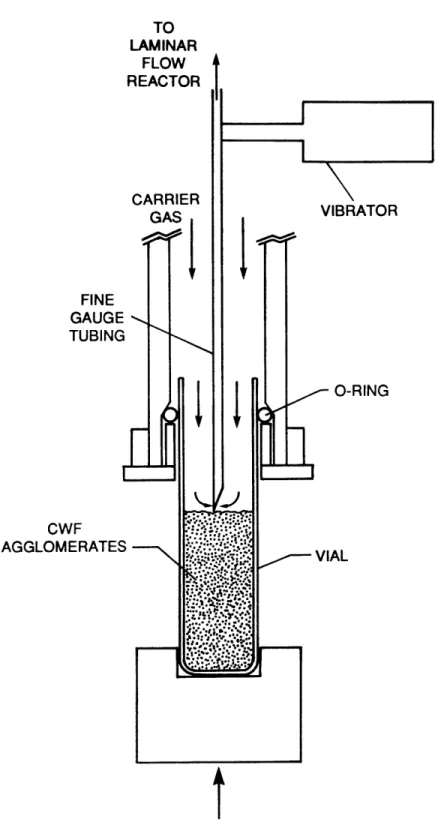
A schematic diagram of the solid-sample feeding system is presented in Figure 15. The CWF agglomerates were entrained by the inert carrier gas, which flowed over the surface of the agitated coal bed and into the stationary fine-gauge tubing. The gas velocity in the fine-gauge tubing was sufficient to keep the particles in suspension. The rate of
entrain-ment was established by the rate at which the coal feed vial was driven
towards the stationary fine-gauge tubing by the syringe pump. A range of feeding rates from 1.7 x 10~4 g/sec to 1.7 x 10⁻³ g/sec was obtainable by
changing the speed of the syringe pump. For a given syringe setting, a
fixed clearance between the top of the coal bed and the fine-gauge tube
was established after an initial transient.
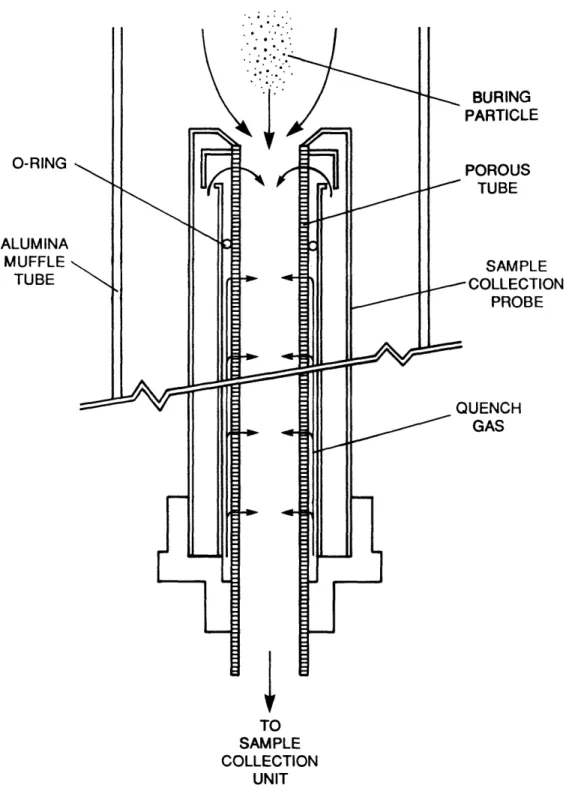
2.3.3 Collection Probe
A schematic diagram of the collection probe is presented in Figure 16. The inner core of the water-cooled collection probe was fitted with
a stainless steel porous tubing through which gas was transpired. The
1.27-cm-I.D. porous tubing was constructed from fused 5-pm stainless
steel spheres. In the top 2.5-cm section of the probe, the combustion products were rapidly quenched at a rate of 1.0 x 10~ *C/sec, by a flow
TO LAMINAR FLOW REACTOR FINE GAUGE TUBING CWF AGGLOMERATES
Figure 15. Schematic Diagram of Solid-Sample Feeding System
BURING PARTICLE O-RING POROUS TUBE ALUMINA MUFFLE SAMPLE TUBE COLLECTION PROBE QUENCH GAS TO SAMPLE COLLECTION UNIT
Figure 16. Schematic Diagram of Sample Collection Probe (CWF Agglomerate Injection)
rate of 300 cm3/sec of nitrogen. A minimal, inward radial gas flow rate
of 66 cm3/sec of nitrogen, which corresponded to a gas velocity of 3.5
mm/sec, was maintained through the subsequent section of porous tubing to counter the thermophoretic velocity of the particles (e.g., 0.18 mm/sec), thereby preventing particle deposition on the inner wall of the probe.
2.3.4 Fiber Optic Radiometer
Figure 13 shows a schematic diagram of the fiber optic radiometer(5) used to measure the radiation from the burning particles. A lens located at the bottom of the laminar flow reactor was used to focus the radiation from the burning particles. The particles were viewed against a dark
background consisting of a water-cooled collection probe. The signals
were measured by individual photomultiplier tubes, after passage through filters with effective wavelengths of 450 and 550 nm and band widths of 5 and 7 nm.
The system was calibrated with a tungsten-strip lamp, and provided a temperature resolution of 30 K at 3500 K.
CHAPTER 3
EXPERIMENTAL OBSERVATIONS OF CWF DROPLET COMBUSTION
3.1 Introduction
Based on high-speed cinematography and fiber optic radiometry the different stages in the CWF droplet/agglomerate combustion process (Figure 17) can be described as follows:
(1) Injection of the CWF droplet (2) Drying of the CWF droplet
(3) Agglomeration and swelling during the coal plasticity period (4) Localized ignition followed by spread of ignition
(5) Volatile flame formation
(6) Rotation induced by the volatile evolution
(7) Extinction of volatile flame and ignitioa of char
(8) Fragmentation both during devolatilization and char burnout (9) Ash shedding and completion of char burnout
The mechanism of CWF droplet/agglomerate combustion is shown in the sequential photographs which are reproduced from the high-speed cinematography in Figures 18 and 19. The time interval between each sequential photograph is labeled in these figures. The novel features of
the results are the high frequency of rotation (up to 3000 cycles/sec)
and fragmentation of the CWF agglomerates, which have important ramifica-tions on the space requirements for combustion and the problems of
* The term of CWF droplet will be used before the drying stage, and the
term of CWF agglomerate, instead of CWF droplet, will be used after the drying stage.
CWF DRY AGGLOMERATE CWF FUSED 'I-PARTICLE ROTATION INDUCED BY VOLATILE EVOLUTION IGNITION AT ONE CORNER FOLLOWED BY SPREAD OF IGNITION FRAGMENTATION & ROTATION DURING DEVOLATILIZATION F M at FRAGMENTATION DURING CHAR BURNOUT -
-CHAR BURNOUT & ASH SHEDDING
Figure 17. Mechanism of CWF Droplet Combustion CWF
DROPLET
r'
If
0.7 msec
1.7 msec
4,.Y
1.7 msec
Figure 18. Sequential Photographs from High-Speed Cinematographs of CWF Droplet Combustion (Agglomerate Diameter - 150 pm,
Furnace Gas Temperature - 1100 K, Oxygen Partial Pressure
- 100 %)
0.3 msec
0.7 msec
0.7 msec
0.3 msec
1,
03 msec
U
0.3
msec
0.3 msec
Figure 19. Sequential Photographs from High-Speed Cinematographs of CWF Droplet Combustion (Agglomerate Diameter - 200 pm,
Furnace Gas Temperature - 1100 K, Oxygen Partial Pressure
- 100 %)
0.3 msec
0.9 msec
erosion due to ash particles. The different stages in the CWF droplet combustion process, described above, will be discussed in detail in
Sections 3.2 through 3.7.
3.2 Ignition
Upon injection of the CWF droplet into the furnace, the interstitial
water of the CWF droplet begins to evaporate. High-speed cinematography with transmission light shows that the coal particles within the CWF droplet adhere to each other, due to surface tension force. Once the
outer film of water is removed, the coal particles on the surface of the CWF droplet are exposed to the hot environment. The coal particles
become plastic and fuse on the outer perimeter of the CWF agglomerate.
Due to the spatially non-uniform heating of the CWF agglomerate, volatile evolution and ignition occur locally at one corner of the CWF agglomerate, quickly followed by spread of ignition to the whole surface
(Figures 20-A and 20-B).
3.3 Volatile Combustion
During devolatilization, the volatiles, emerged from the CWF agglomerate surface, burn rapidly with the available oxygen. If the volatile evolution is fast enough to displace oxygen from the CWF
agglomerate surface, an envelope flame forms around the CWF agglomerate
(Figures 18 and 19). The visible light emission is radiation from the
soot formed by the cracking of hydrocarbon species in the fuel-rich region between the CWF agglomerate surface and the envelope flame.
0 3 msec '&
0.6msec
,0 0.3 msec i0.3
msecA
iq > 0.3 msec 43r na
msec 'q, 0.6 msec 0.6 msecB
Figure 20. Sequential Photographs from High-Speed Cinematographs of
CWF Droplet Combustion; Localized Ignition Followed by
Spread of Ignition (Agglomerate Diameter - 100 pm in Figure A and 130 pm in Figure B, Furnace Gas Temperature
volatiles and soot, but is heated by the energy fed back to the surface
by the envelope flame. The radiation from the burning agglomerate is
predominantly from soot particles in the high temperature zone near the
flame front. The surface temperature of the CWF agglomerate is relatively low compared to the flame temperature, as evidenced by the dark core at the center of the envelope flame in the high-speed photographs (Figures 18 and 19).
The duration of the volatile flame for a CWF agglomerate diameter of 75-90 pm and a furnace gas temperature of 1200 K ranged from 5 msec at
100 % 02 to 8 msec at 70 % 02 to 11.9 msec at 50 % 02. There was good correspondence in the volatile combustion times between the in-situ
generated CWF droplets (5.02 msec at 100 % 02) and re-injected CWF agglomerates (5.34 msec at 100 % 02), suggesting that the latter could be
(6)
substituted for further experimentation . At low-oxygen concentrations
(less than 20 % 02) the volatiles evolved do not burn in a sharp flame
envelope, rather, they undergo oxidation in the bulk gas phase resulting in the formation of diffuse soot clouds and trails (Figures 21 and 22).
3.4 Particle Rotation
Some fraction of the volatiles is ejected from the CWF agglomerate
in the form of jets. The centrifugal force, generated from the momentum of the tangentially issuing jets, imparts rotation to the CWF agglomerate. High-speed photographs (Figures 18, 19, and 20-B) show that the CWF agglomerates rotate randomly in both clockwise and counter-clockwise fashion.
a
2.6 msec
b
4.4 msec
C
Figure 21. Sequential Photographs from High-Speed Cinematographs of CWF Droplet Combustion; Soot Clouds and Soot Trails (Agglomerate Diameter - 50-200 pm, Furnace Gas
a
1.8 msec
b
1.8 msec
C
Figure 22. Sequential Photographs from High-Speed Cinematographs of CWF Droplet Combustion; Soot Clouds and Soot Trails (Agglomerate Diameter - 150 pm, Furnace Gas Temperature
Measurements, by fiber optic radiometry, of the radiation emitted by CWF agglomerates burning in suspension, diluted enough that only one
ag-glomerate at a time is in the field of view, provide information about
the different aspects of the combustion process and combustion time. Particle rotation can also be discerned from the intensity traces of radiation emitted by the devolatilizing/burning CWF agglomerates. Periodic oscillations in the radiation intensity traces of the CWF agglomerates are shown in Figure 23. These rotations correspond to non-spherical agglomerates which, therefore, exhibit a varying cross-sectional radiating area upon rotation. Angular velocities in Figures
23-a, 23-b, and 23-c are approximately 800, 1400, and 2800 cycles/sec,
respectively, for an agglomerate diameter of 100 pm, an oxygen partial pressure of 100 %, and a furnace gas temperature of 1750 K. An angular velocity of 1000 cycles/sec for an 100-pm-diameter agglomerate generates centrifugal force of 200 G at the agglomerate surface. This can promote separation of weakly adhering coal particles from the CWF agglomerate during devolatilization, and of fine ash particles and fragments of char from the CWF agglomerate during char burnout. Heat and mass transfer rates to the agglomerate are, however, not significantly affected because of the relatively small rotational slip velocities (0.31 m/sec for an 100-pm-diameter agglomerate at an angular velocity of 1000 cycles/sec) between the agglomerate surface and the surrounding gas.
3.5 Ignition of Char
When the rate of the volatile evolution decreases, towards the end
0
4
8
TIME (msec)
Figure 23. Radiation Intensity Traces of Rotating CWF Agglomerate (Agglomerate Diameter - 100 pm, Furnace Gas Temperature = 1750 K, Oxygen Partial Pressure - 100 %)
(a) 800 cycles/sec, (b) 1400 cycles/sec, (c) 2800 cycles/sec 100