Publisher’s version / Version de l'éditeur:
Vous avez des questions? Nous pouvons vous aider. Pour communiquer directement avec un auteur, consultez la première page de la revue dans laquelle son article a été publié afin de trouver ses coordonnées. Si vous n’arrivez pas à les repérer, communiquez avec nous à [email protected].
Questions? Contact the NRC Publications Archive team at
[email protected]. If you wish to email the authors directly, please see the first page of the publication for their contact information.
https://publications-cnrc.canada.ca/fra/droits
L’accès à ce site Web et l’utilisation de son contenu sont assujettis aux conditions présentées dans le site
LISEZ CES CONDITIONS ATTENTIVEMENT AVANT D’UTILISER CE SITE WEB.
Paper (National Research Council of Canada. Division of Building Research); no.
DBR-P-1227, 1984
READ THESE TERMS AND CONDITIONS CAREFULLY BEFORE USING THIS WEBSITE. https://nrc-publications.canada.ca/eng/copyright
NRC Publications Archive Record / Notice des Archives des publications du CNRC : https://nrc-publications.canada.ca/eng/view/object/?id=10885cbc-609a-4e8e-a51f-d6e895f6553c https://publications-cnrc.canada.ca/fra/voir/objet/?id=10885cbc-609a-4e8e-a51f-d6e895f6553c
NRC Publications Archive
Archives des publications du CNRC
This publication could be one of several versions: author’s original, accepted manuscript or the publisher’s version. / La version de cette publication peut être l’une des suivantes : la version prépublication de l’auteur, la version acceptée du manuscrit ou la version de l’éditeur.
For the publisher’s version, please access the DOI link below./ Pour consulter la version de l’éditeur, utilisez le lien DOI ci-dessous.
https://doi.org/10.4224/40001721
Access and use of this website and the material on it are subject to the Terms and Conditions set forth at
Failure probabilities of construction designed for fire resistance
Ser
I TILl IN2ld
National Research
Conseil national
no.
1227I
I
*
Council Canada
de recherches Canada
c. 2FAILURE PROBABILITIES OF CONSTRUCTIONS DESIGNED FOR FIRE RESISTANCE
by J.R. Mehaffey and T.Z. Harmathy
ANALYZED
Reprinted from Fire and Materials, Vol. 8, No. 2, 1984 p. 96
-
104DBR Paper No. 1227
Division of Building Research
Price $1.00 OTTAWA
La "charge thermique n o r m a l i ~ ~ " permet d'e'valuer l e p o t e n t i e l d e s t r u c t e u r d e s i n c e n d i e s de compartiment r'eels e t d e s i n c e n d i e s d ' e s s a i . Pour l e s i n c e n d i e s r g e l s , l e concept comporte c e r t a i n e s i n c e r t i t u d e s d u e s 3 l a n a t u r e s t o c h a s t i q u e d e deux d e s v a r i a b l e s d o n t il dgpend: l a v e n t i l a t i o n e t l a c h a r g e combustible. Pour l e s i n c e n d i e s simul'es, il y a d e s i n c e r t i t u d e s d u e s
3
l ' a s p e c t al'eatoire q u i c a r a c t ' e r i s e l e s r ' e s u l t a t s d ' e s s a i . On d g c r i t d a n s c e t t e d t u d e une mgthode d e c a l c u l de l a p r o b a b i l i t ' e d e d g f a i l l a n c e d e s p a r o i s d'un compartiment conGu pour r ' e s i s t e r au f e u , basOee s u r d e s i n f o r m a t i o n s c o n c e r n a n t l e s caract'er i s t i q u e s du compartiment e t l a v a l e u r d e c a l c u l d e l a c h a r g e combustible. La m6thode e s t d i r e c t e e t n e f a i t a p p e l 5 d e s c o n s i d ' e r a t i o n s s t a t i s t i q u e s q u e l o r s q u e l a n a t u r e de c e r t a i n e s v a r i a b l e s d t e n t r 6 e l ' e x i g e .Failure Probabilities of Constructions Designed
for Fire Resistance
J. R. MehafEey and T. Z. Harmathy
National Research Council of Canada, Division of Building Research, Ottawa, Canada KIA OR6
'Normalized heat load' is a quantifier of the destructive potential of fires, real-world compartment fires and test fires alike. For real-world fires it is subject to some uncertainties owing to the random nature of two of the variables it depends on: ventilation and 6re load. For test fires also it is subject to uncertainties owing to a moderate degree of randomness that characterizes the results of test fires. A plocedure is d e s c n i for predicting the faihue probability in 6re of the boundaries of a compartment designed for fire resistance on the basis of information concerning the characteristics of the compartment and the design value of the fire load. The procedure is essentially deterministic, employing statistical considerations only as far as required by the nature of some of the input variables. With the aid of second-moment analysis, it is possible, fortbermore, to design the compartment boundaries for appropriate target failure probab'ies.
INTRODUCTION CONCEIT OF NORMALIZED WEAT LOAD
For the past several decades the provision of structural measures of fire safety has been a focal point of fire protection. Such measures have been based on the concept of fire resistant compartmentation, which pic- tures all building compartments as perfectly isolated from each other and the spread of fire as taking place by successive destruction (or possibly thermal failure) of compartment boundaries. If these boundaries are of sufficient fire resistance, it is argued, the possibility of fire spread will be kept within acceptable limits.
The idea of a perfectly isolated compartment is, of course, only a crude abstraction. Information gathered over the past fifty years clearly shows that building fires spread mostly by convection (by the advance of flames and hot gases through various openings inter- connecting compartments) rather than by destruction. In spite of this, present fire safety design does not fully recognize the possibility of convective spread. Al- though this paper deals only with the issue of defence against fire spread by destruction, the authors find it necessary to emphasize by way of introduction that the provision of structural measures addresses only part of the overall fire spread problem.
The relationship between the failure probabilities in fires of compartment boundaries and their fire resis- tances will be investigated in this paper. Procedures will be described for designing compartment bound- aries to achieve target failure probabilities. It makes use of the normalized heat load, a quantifier of the destructive potential of post-flashover fires.
It should be noted that this paper is concerned only with the conditional probability of failure, given that flashover has occurred, and there will be no intenen- tion by the fire department. The overall probability of failure incorporates some other factors, such as those related to the likelihood of ignition, flashover and some others related to the efficiency of the operation of the fire department.
The essence of fire resistant compartmentation is to subdivide the building into smaller units, or compart- ments, in which fire can be localized and suppressed. The units must be separated from each other by fire resistant boundaries and, in addition, the load-bearing skeleton of the building must be fire resistant.
Fire resistance is looked upon as a true product descriptor. It is the length of time the building element (product) in question is capable of withstanding the destructive potential of a standard test fire. Although for some building elements the fire resistance can be determined by calculation, it is usually determined by subjecting a specimen to a fire test.
Determination of fire resistance is a relatively straightforward, though not necessarily simple, task. Determination of the requirements that will ensure satisfactory performance of the building if fire pro- ceeds beyond flashover in any compartment is consid- erably more complex. The finding that the destructive potential of fires, real-world fires and test fires alike, can be quantified by a single parameter, the 'nor- malized heat load', was an important step towards solving the problem.'-3 The normalized heat load, H (s1I2 K), is defined as
I r ~ *
where q is the heat flux penetrating the boundaries of an enclosure (building compartment or test furnace) exposed to fire (W mP2), t is time (s), T* is duration of
fire exposure (s), and J(kpc) is the thermal inertia of the enclosure boundaries (J m-2 s-'I2 K-') (k is ther- mal conductivity, p is density and c is specific heat).
According to the theorem of uniformity of nor- malized heat load, H is approximately the same for the fire enclosure as a whole as for the individual boundary elements. This implies that the destructive spread potential of fire is the same for all boundary
FAILURE PROBABILlTIES OF CONSTRUCTIONS DESIGNED FOR FIRE RESISTANCE I
I
'
elements of the compartment. The concept of nor- malized heat load is not applicable to boundary ele- ments made entirely from materials of high thermal inertia, for example, from unprotected steel or aluminum.
Drawing on the concept of normalized heat load, determining the fire resistance requirements is as sim- ple as requiring that the building elements be able to endure in a test fire a normalized heat load (denoted , by H") equal to or greater than the normalized heat
1
load expected to be imposed on the same buildingelements in real-world fires (denoted by H'). In re-
I
ality, the problem is somewhat more complex. Tounderstand the reasons, it is necessary to examine the variables on which H' depends and the factors that cloud the meaning of H".
- -
I
REAL-WORLD FIRESThe most important variables on which the normalized heat load in real-world compartment fires depends are:3
A, floor area of compartment (m2)
A, total area of compartment boundaries (m2)
h, height of compartment (m)
J(kpc) surface-averaged thermal inertia of compart- ment boundaries (J mP2 s-li2 K-l)
<p. ventilation factor characterizing the rate of air flow into the compartment (kg s-l)
L specific fire load (mass of combustibles per
unit floor area) (kgm-')
Values for the first three variables are available from the building plans. The fourth is calculable from the planned use of building materials.' The last two variables, ventilation factor and specific fire load, can be modeled as random variables. The former may vary with climatic conditions, building height and other factors related to the building design and state of the compartment at the outbreak of fire. There is little information on its frequency distribution. It is proba- ble that values close to its minimum (to be discussed later) occur with a high frequency.
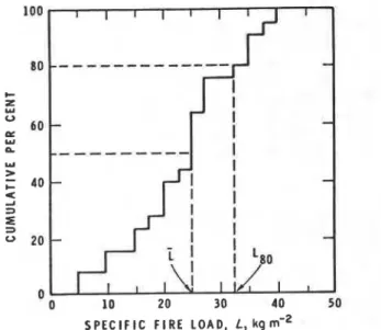
The specific fire load is largely a function of building occupancy, but even for the same occupancy class it may vary in an unpredictable fashion. A typical cumulative plot is shown in Fig. 1. It is assumed, mainly for convenience, that the frequency distribu- tion of specific fire load follows the normal distribution pattern, acknowledging that other choices may be slightly more a ~ c u r a t e . ~ Thus, the probability density, pL (m2 kg-'), will be described by the equation
1
PL = exp [ - ( L - L)2/2aL2]
ur. J ( 2 r ) (2)
where is the median (kg m-') (see Fig. 1) and a, is the standard deviation (kg rnp2). Information on specific fire load, based on Swedish data,' is presented in Table 1.
In room-bum experiments the values of the ventila- tion factor and the specific fire load can be carefully set. Under such conditions the following approximate
Figure 1. Customary presentation of information on specific fire load.
equation is applicable to the normalized heat load?
where 6 (dimensionless) quantifies the fraction of the fuel energy released in the flaming combustion inside the fire compartment. (The fuel decomposes in fire and part of the energy of the gaseous decomposition products is released in the flames emerging from the compartment.) An approximate equation for 6 is
= (0;79J(h,"/@) whichever is less (4) (This calculation technique for normalized heat load is used in the DBRINRCC laboratory. Strictly speaking, it is applicable only if the fire load consists wholly of cellulosic materials. The validity of the essential con- clusions of this paper is, however, not tied to the calculation technique employed.)
Since @ and L are random variables, by virtue of Eqns (3) and (4) the normalized heat load in real- world compartment fires, H', is also a random vari- able, although in a different sense. It seems advisable to introduce at this point two definitions related to the nature of randomness: (1) an intrinsically random variable-a simple, well-defined input variable that may vary in a random fashion; (2) an extrinsically random variable--one that shows a random variation
Table 1. Information on 6re loadS Specific fire load
(kg 6') Standard O c c u ~ n c v Average deviation Dwelling 30.1 4.4 Office 24.8 8.6 School 17.5 5.1 Hospital 25.1 7.8 Hotel 14.6 4.2
J. R. MEHAFEY AM) T. Z . HARMATHY
I
by virtue of being a function of one or more intrinsi- cally random variables. Thus, @ and L are intrinsically random variables, and H' is an extrinsically random variable. (Some degree of uncertainty associated with the use of Eqns (3) and (4) in calculating H' is a further, though at this time unknown, factor in the extrinsically random nature of H'. Uncertainities as- sociated with calculation techniques will be referred to as 'model uncertainties.')
TEST
FIRES
As the temperature history of standard test fires is uniquely defined, the normal% heat load on speci- mens of building elements. W, is a function only of
the duration of fire test.
(This
statement is only ap-proximately correct. There are secondary factors that may influence the nature of the relation between W
and the duration of a fire test.2) That function is shown in Fig. 2 for a highly efficient test furnace heated with 'black' gases and for the floor test furnace of the
DBRINRCC laboratory. Here T denotes length of
exposure to the test fi;e (in h). If the test
specimen
performs satisfactorily during that time, T quantifiesthe fire resistance of the building element the speci- men represents.
The relation between normalized heat load in stan- dard fire tests and length of testing (if the test speci- men does not fail during that period, it is the measure of fire resistance) is described by the following equa- tion:
This is an approximate representation of curve 2 in Fig. 2. (As will be seen, making the expression explicit for T has some advantages in the design procedure.)
Fire resistance, viewed as a product descriptor, is also a random variable. Its randomness is due to two factors: (1) the test specimen may not be fully rep- resentative of its real-world counterpart, mainly be- cause of differences in workmanship or scatter in
LENGTH OF E X P O S U R E TO S T A N D A R D TEST F I R E . T h Fmure 2. Correlations between H" and T for standard fire tests
Curve 1-for a black-gas furnace; Curve 2-for the floor test
furnace in the DBR/NRCC laboratory (estimated).
98 FIRE AND MATERIALS, VOL. 8, NO. 2, 1984
material properties; and (2) the measured fire resis- tance, on account of small differences in fire test facilities or loading practices, may show some varia- tion from one laboratory to another. It is again as- sumed, mainly for convenience, that the frequency distribution follows the normal distribution pattern; the probability density, pT (h-l), can therefore be de- scribed as
1
PT = exp [-(T - ~)~/2u72]
~TJ(2.rr) (6)
where ? is the median (h) and uT is the standard deviation (h). According to an ASTM study: (ad?) is somewhere between 0.01 and 0.15. devending on the ,
.
type of construction. (This information relat& to the majority of building elements. For prestressed con- crete beams the spread of fire resistance may be substantially greater3
As mentioned earlier, fire safety design consists essentially of comparing values of the normalized heat load in real-world fires, H', with those in test fires, H". As fire resistance, T, has been regarded as an intrinsi- cally random variable (see Eqn (6)), it follows from Eqn (5) that H" is an extrinsically random variable.
DESIGN FIRE RESISTANCE REQ-
As fire safety design must address reasonably adverse conditions that may arise in real-world compartment fires, the design values of the two random variables, @ and L, should be selected to represent such adverse conditions. A glance at Eqn (3) will reveal that the normalized heat load H' (i.e. the destructive potential of real-world fire) decreases monotonically with in- crease in ventilation factor @. Thus, as f a r as ventila- tion is concerned, the most detrimental conditions occur at low values of @. Two questions arise: is there a well-defined minimum for @ and, if so, is the design anived at by the use of that minimum overly conser- vative? The answer to the first question is yes. The rate of air flow into the compartment (proportional to @) is a minimum when it is not augmented by drafts or winds. Under such conditions the ventilation factor is determined by the dimensions of the ventilation open- ing as follows:
@ ~ , = paAvJ(ghv) (7)
where pa is density of atmospheric air (kg rnw3), Av is the area of ventilation opening (m2), g is gravitational constant (m sP2) and hv is the height of the ventilation opening (m).
By substituting different values of @ in Eqn (3) one finds that under normal circumstances the maximum value of H' (which occurs when @ = @-,) is rarely more than twice that which may arise at very high ventilations (when @ may go as high as five or six times
.
)
a
,
It follows that the answer to the second question is no. It is reasonable, therefore, that ,@, as defined by Eqn (7) be regarded as input value for fire safety design.Focusing attention now on the other random vari- able, specific fire load L, one finds that the normalized heat load increases monotonically with increase in L
FAILURE PROBABILITIES OF CONSTRUCTIONS DESIGNED FOR FIRE RESISTANCE
(see Eqn (3)). Again, is there an absolute maximum for L, and, if so, is it reasonable to use this maximum in design considerations? The answer to the first ques-
I
tion is yes. Clearly, the combustibles that can be present in a compartment are limited by the volume of the compartment. L,, is about 900 kg mP2; but if the compartment is filled from top to bottom with com- bustibles, they cannot bum for lack of air. Thus, the
i
answer to the second question is no.It is estimated that even if the compartment is used
I as a storage room, the combustibles that can burn in a fire cannot be much more than about 150 kg m-2. But
I
this value is still overly conservative for design. Statis- tical data indicate that, depending on the type of occupancy, the specific fire load has a mean betweenI 15 and 45 kg mP2 and rarely exceeds 100 kg mP2.
How, then, should a design value be selected? If the median value
L
is selected (see Fig. I), the design may be inadequate in roughly 50% of the cases. If a value much higher than L is selected, the cost of fire protec- tion may greatly increase. In this paper specific fire loads applicable to either 80% or 95% of cases are considered as potential design values. (The meaning of this 80th percentile, Lao, is illustrated in Fig. 1.)Assuming a normal distribution, Lao and-Lg5 can be described with the aid of the median, L, and the standard deviation a,, as follows:
After deciding on the design values for and L (namely
ad
= a-, and L, = L, or L,,), one can proceed to calculate the design value of the nor- malized heat load on the compartment in question, H' (Eqns (3) and (4)), i.e. the destructive potential of a 'design' fire. Clearly, specimens of the compartment boundaries must be capable of withstanding the same destructive potential in standard fire tests. By equating H' with H", the 'design' fire resistance requirements, rd, can be calculated from Eqn (5).In general, the fire resistance of the building ele- ments actually used greatly exceeds the value con- templated by design for the following reasons. The fire resistance of various building elements is always listed by the testing laboratories in rounded-up values: 0.5, 0.75, 1.0, 1.5,2.0,
.
.
.
(h). Thus, if the design value for fire resistance is, for example, rd = 1.12 h, the applica- ble building elements have to be selected from among those whose fire resistance is listed as 1.5 h. In gen- eral, the relation between the design fire resistance requirement, rd, and the fire resistance available from the listing provided by the testing agencies, r,, is+ where O S a G 0 . 5 .
It is extremely rare, however, for the actual test value of fire resistance of the building element selected, r,, to be one of the rounded values that appear in various listings. Thus, a building element listed as having a fire resistance of, say, 1.5 h usually has a fire resistance somewhere between 1.5 and 2.0 h or possibly even greater. (Failure is not always reached
by the end of the test.) One can write, therefore,
where b2-0.
Naturally, fire resistances in the foregoing three interpretations should also be looked upon as a ran- dom quantities subject to variations about the medians of rd, r1 or rt, as characterized by Eqn (6).
The question that remains to be resolved is: what is the probability of structural (or thermal) failure in fire in a building composed of elements selected on design considerations described earlier? (The probability of failure to be considered here is conditional probability. It is tacitly assumed that there will be no intervention by the fire department and that the compartment fire has undergone flashover. Usually it is only post- flashover compartment fires that present threats to the structural integrity of building elements.)
FAILURE PROBABILITY
The procedure for calculating failure probability will be outlined here in connection with a numerical exam- ple. Further details of the calculation procedure are given in the Appendix. The failure probability of the boundaries of an office comvartment, described ear- lier,' will be examined:
A,'=
24.0 rnZ, A, = 9 1.5 m2,h, = 2.4 m, ,/(kpc) = 964 J mL2 s-li2
K-'
7 @ d n =20.8 kg sL1, design fire load = 38.9 kg mP2.
The
fireload is essentially cellulosic. Using Eqns (3) and (4) (with
ad
=amin
and Ld = L,,), the following design value is obtained for the normalized heat load:Applying Eqn (5), the design value for the fire resis- tance is rd=0.88 h.
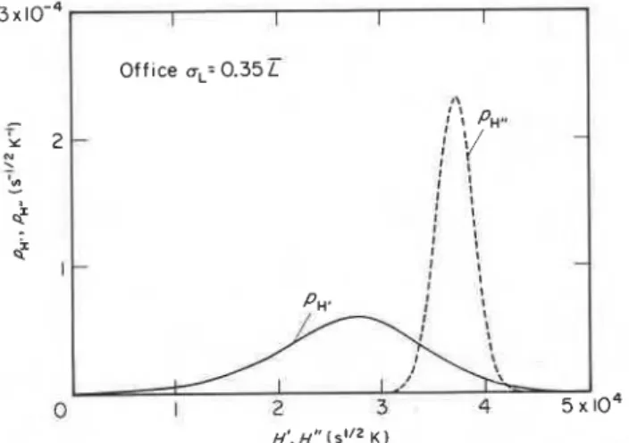
In Fig. 3 the solid curve shows the probability density for the normalized heat load in real-world fires that could develop in this compartment, pH, (s-'I2 K-'
1
,calculated using :he frequency distribution given by Eqn (2) for L (L = 24.8 kg m-2, a,= 8.6 kg mP2, see Table 1) and assuming that
ad
=a,,
= 20.8 kg sP1. The dashed curve represents the probability density ofFigure 3. Probability densities for the normalized heat load in real-world fires ( L normally distributed, and test fires (T normally distributed about the median 7,).
J. R. MEHAFFEY AND T. Z . HAFWATHY
the fire resistance of the building element to be consi- 0.075 I I I
dered, p , . (sel" K-l), expressed in terms of nor- I
malized heat load, HI', with the aid of Eqn (5). It has ~ f f ~ c e q = 0.35
been calculated on the assumption that the median for
the fire resistance is equal to the 'design' fire resistance Curve o T,, = 0.88 h
requirement, rd=0.88 h, and that the frequency dis- b T, = 1.00 h
tribution for r is that given by Eqn (6) (uv = 0.05 T ~ ) . c T, = 1.2 h
The
failure probability for these conditions, P, (di- 0.025-
mensionless), can be calculated from the following equation :
Pf=
h d H ' p ~ d H ' ~ (11)1.00 1.05 HSH'
The various mathematical manipulations involved in 5. Failure as function of and fire
solving this double-integral are given in the Appendix. resistance of the construction.
The result of the calculations is
P,
= 0.059.The reader is now reminded ihat the ventilation factor, @, is also a random quantity, although its frequency distribution cannot be represented at this time by a known analytical expression. To discover the effect of @ on P, three probability density curves have been calculated for
R
using, as before, the frequency distribution forL
given by Eqn(2)
but assigning toad
three different values:a
,
,
,
1.2 and 1.4cP,,.
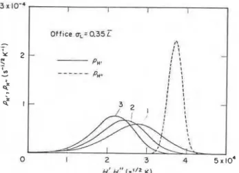
These are shown as solid curves 1, 2 and 3, respec- tively, in Fig. 4. The meaning of the dashed curve is the same as in Fig. 3. The results of these and addi- tional calculations-of P, employing Eqn (11) are pre- sented as curve a in the P, vefius
@/a,,
plot in Fig. 5. It may be seen that, as expected, the failure proba- bility decreases rapidly with increase in ventilation caused, for example, by draughty conditions in the building.Figure 6 illustrates a further extension of the inves- tigations. As discussed earlier, the fire resistance of the building elements contemplated for use is generally higher than the fire resistance required by design. In the numerical example discussed, 7, = 0.88 h. The rounded value of fire resistance that falls in line with listings is T, = 1.0 h. The fire resistance of the selected building element, obtained by testing, is assumed to be
T,= 1.2 h. The probability densities for these three
levels of fire resistance are plotted in terms of nor-
1 I I I Office q.0.35 "t 4' I I t
-
- Pn* 4 ' :---
I I I I I I ; ; ; !-
Figure 4. Probability densities for the normalized heat load in real-world fires ( L normally distributed, ad = a,,,, 1.2 a,,,,,,, 1.4
a,,,) and test fires (T normally distributed about the median
74).
malized heat load, pH,., in dashed lines a, b and c, respectively, together with the three p, curves (solid lines) already discussed in connection with Fig. 4 (representing three levels of ventilation). The results of the calculations are plotted in Fig. 5. It may be seen that if the fire resistance requirements are determined by proper design and the building elements are then selected by the usual practical considerations, the probability of failure of these elements in a (post- flashover) fire is usually negligible.
DESIGNING
FORTARGET
FAILUREPROBABILITY
The usual problem that arises in practice is not how to calculate the failure probability of compartment boundaries designed according to an accepted proce- dure, but how to spec* the random variables of the fire process so that a target failure probability can be realized.
A very simple method of designing for target failure probability can be devised on the assumption that specific fire load, L, is the only variable the random- ness of which need be considered. That assumption is, in fact, not unrealistic, since, as discussed earlier, with the selection of @ = a h , a safe condition is ensured with respect to ventilation, and since the coefficient of
Figure 6. Probability densities for the normalized heat load in real-world fires ( L normally distributed, %=@,,,, 1.2 a,,,, 1.4 a,,,) and test fires (7 normally distributed about the medians
Td, 71, 7*).
FAILURE PROBABILITIES OF CONSTRUCTIONS DESIGNED FOR FIRE RESISTANCE
0.001 0 . 0 1 0.1 1
4
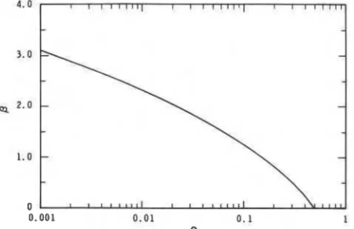
Figure 7. Correlation between the factor f3 and the probability of failure in fire, P,.
variation for the fire test results, (oJr), is as a rule not more than 0.15.
If the specific fire load is expressed, analogously to Eqns (8a) and (8b), as
with the selection of the value of
p
the failure proba- bility, P,, can be controlled at the desired level.p
as a function of P, is plotted in Fig. 7.A value for L defined according to Fig. 7 and Eqn (12), when used in Eqn (3), will yield a design value for Ht which, in turn, when substituted into Eqn (5)
(remembering that the condition of satisfactory perfor- mance of a building element in fire is Ht12H') will vield a value for the fire resistance. r. that ensures that ihe failure probability for the building element will not exceed P,.
A more elegant method, which can be expanded to cover the other principal random variable, the fire resistance test results, r, at this time and perhaps also the ventilation, @, some time in the future, is based on the 'second-moment
According to the latter technique, the probability of failure for the compartment boundaries will not ex- ceed P, if the fire resistance of the boundary elements,
7, is selected from the following modified form of Eqn
( 5 ) :
7 = 0 . 1 1 + 0 . 1 6 ~ 1 0 - ~ ~ + 0 . 1 3 x l ~ - ~ ( p ) ~ (13)
I
whereand
p
anda
are the medians for H" and H',respectively, and a,,, and oH' are standard deviations for H" and Ht, respectively.
6
is a safety index which is related to the target value of failure probability, P,,i as shown in Fig. 7. (The curve in this figure is to be
I considered as approximate. It is exact only if In H"/H'
i'
is normally distributed.) The mean value of H' is determined by substituting L = in Eqn (3).Since, as discussed earlier, the frequency distribu-
I tion of @ (ventilation factor) is not known, @ can again
'
be taken into account with its most adverse value,@-. (Clearly, at this time the model uncertainties cannot be taken into consideration either; however,
the adverse selection of @ is believed to keep the solution on the safe side.) With this simplification, Ht
can be looked upon as an extrinsically random vari- able dependent on one intrinsically random variable, namely, the fire load, L.
According to Eqns (13) and (14), the solution of the problem requirez information _on two coefficients of variation, (cT~*,/H~') and (uH,/Ht). Following Zahn,8 one has
where H' and r stand for their expressions presented by Eqns (3) and ( 3 , respectively. After performing the differentiation in Eqn (15) the following equation is obtained for the coefficient of variation, (oH'/Hf):
Obviously,
Ir ($)/&)<I
2
Finding an expression for (oH'./il") is a more com- plex task. After performing the differentiation in Eqn (16) and rearranging the equation,
Clearly, the problem arises here that to calculate (uH,,/I?') one has to know I?, which in fact, according to Eqn (14), is the quantity to be sought. Two ap- proaches are possible. One can either solve Eqns (14) and (19) simultaneously for the two unknowns, I? and (uIFr/If"), or one can find an approximate expression for (ow/I?). The latter approach will be used here.
Using Eqn (19), (uIFr/H')/(uJi:) is plotted in Fig. 8 for a range of values of
p
which, according to Fig. 2, are ofgractical interest. It is seen that the variation of (oH',/Ht')/(oT/?) is rather small for I?> 2 x lo4, i.e. for fire tests that last longer than about 0.5 h. Apparently, the following equation represents a fair approxima- tion:Figure 8. The relationship between (u"/Fl")/(uJ.i.) and
a".
J. R. MEJ+WFEY AND T. Z . HAFWATHY
0 . 2 5
-
-
0 . 0 0
-
I I I I1 . 0 0 1 . 2 5 1 . 5 0 1. 75 2 . 0 0 2. 25
+/+
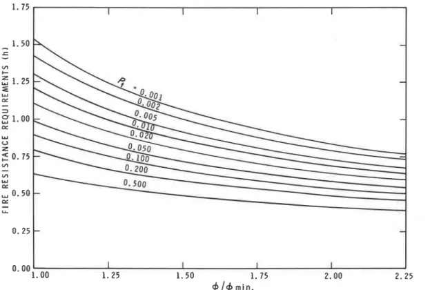
min.Figure 9. Fire resistance requirements (for the office compartment discussed) to realize various failure probabilities, as functions of ventilation.
The coefficient of variation for the results of fire resistance tests, (u,/.T), is available from Reference 6. Of course, as before, @ can again be regarded as a variable, such that @a@,,. Figure 9 shows the fire resistance requirements to realize various target fail- ure probabilities, plotted against the ratio @/@-,, for the office compartment discussed in the previous sec- tion. For reasons discussed earlier, the failure prob- abilities decrease markedly with increasing ventilation.
DISCUSSION
Calculation techniques for predicting failure prob- abilities that have been employed in the past differ from the method discussed in this paper. They are based on the concept of equivalent fire resistance time. The equivalent fire resistance time is looked upon as the descriptor of the destructive potential of f i e . Its value is derived from simple expressions that may differ greatly according to the preferences in various countries. All the expressions agree, however, in that they are empirical formulas accounting for, in the simpler ones, fire load and ventilation and, in the more complex ones, rate of burning and compartment geometry and thermal properties of the compartment
I
boundaries as well. It is realized that the equivalentI fire resistance times calculated from those empirical
formulas are subject to large-model uncertainties, and they are therefore treated as random quantities.
Unlike the intrinsically random variables used in the calculation technique described in this paper (namely, fire load and ventilation), the equivalent fire resistance
time is not a quantity of well-defined meaning; it is not directly measurable and, in fact, its interpretation de- pends on the specific formula (model) used. More importantly, because it is a quantity of complex struc- ture, information on its randomness cannot be ob- tained by conventional data collection techniques.
The calculation of failure probability is performed by comparing two random variables: equivalent fire resistance time and fire resistance of the building element selected for use. As discussed, the latter is a variable with a well-defined meaning whose random- ness can be determined by data collection. The tech- nique of comparing the two random variables could be done by using an equation similar to Eqn (11). Realiz- ing the difficulties associated with defining equivalent fire resistance time and its randomness, however, the advocates of the concept of equivalent fire resistance usually aim at keeping the failure probability of selected constructions within acceptable limits by in- troducing empirically assigned safety factors. To take account of the large model uncertainties (i.e. those associated with the use of the empirical formulas in the calculation of the equivalent fire resistance times), these safety factors have to be fairly large.
The calculation technique outlined in this paper requires seven input variables: three-fire load, venti- lation and fire resistance-are intrinsically random. All three random variables are directly measurable, and therefore information on their randomness can be derived by simple data collection techniques. A de- signer can have not only direct insight into the possible range of their variation but also an appreciation of the values to be used in the design.
FAILURE PROBABILITIES OF CONSTRUCI'IONS DESIGNED FOR FIRE RESISTANCE
The failure probability of a specified building ele- ment in a real-world fire is determined by comparing two variables: the normalized heat load characterizing the real-world compartment fire, H', and the max- imum normalized heat load the boundaries of the compartment can endure, as assessed from experimen- tally derived fire resistance of the building element, H". Both H' and H" are extrinsically random vari- ables; their randomness is determined by the random- ness of fire load and ventilation (for H'), and by the randomness of fire resistance (for H''). A paramount
" characteristic of the calculation technique is, therefore,
that it is essentially deterministic, using statistical con- siderations only so far as required by the nature of the three random input variables. Being essentially deter- ministic, the technique allows the designer insight into the cause-effect relations as he derives solutions to his problem.
Acknowledgements
This paper is a contribution from the Division of Building Research, National Research Council Canada, and is published with the ap- proval of the Director of the Division.
REFERENCES
1. T. 2. Harmathy, Fire severity: basis of fire safety design, in fire safety of concrete structures. ACI Publication SP-80,
American Concrete Institute, Detroit (19831, p. 115. 2. T. 2. Harmathy, The fire resistance test and its relation to
real-world fires. Fire Mater. 5, 112 (1981).
3. J. R. Mehaffey and T. 2. Harmathy, Assessment of fire resistance requirements. Fire Technol. 17, 221 (1981). 4. L A. Issen, A literature review of fire and live load surveys
in residences. NBSlR 78-1440, National Bureau of Stan- dards, Washington, DC (1978).
5. 0. Petterson, S. E. Magnusson and J. Thor, Fire engineer- ing design of steel structures, Swedish Institute of Steel Construction, Stockholm, Bulletin 50 (1976).
6. ASTM E5.11 Task Group Report. Repeatability and repro- ducibility of results of ASTM E 119 fire tests. Research
Report No. RR: €5-1003, available from ASTM, Phil. PA (1982).
7. Brandproeven op Voorgespannen Betonliggers. CUR Rap- port No. 13, Commissie voor Uitvoering van Research, Betonvereniging, Holland (1958).
8. J. J. Zahn, Reliability-Based Design Procedures for Wood Structures, For. Prod. J. 27, 21 (1977).
9. F. E. Woeste and E. L. Schaffer, Second moment reliability analysis of fire exposed wood joist floor assemblies. Fire
Mater. 3, 126 (1979).
10. M. Abramowitz and I. A. Stegun, Handbook o f mathemati- cal Functions, Section 25.4.46, Dover, New York (1964). Received 21 December 1982; accepted 22 August 1983 NOMENCLATURE
area (m2)
gravitational acceleration (m s - ~ ) height (m)
normalized heat load (s1I2 K)
normalized heat load under real-world fire conditions (s1I2 K)
median of H' (s1I2 K)
normalized heat load assessed from experi- mentally derived fire resistance (s1I2 K) median of H" (s1I2 K)
thermal inertia (J mP2 s-lI2 K-' )
specific fire load (kg mP2) median of L (kg m-2)
probability density (various dimensions) failure probability (conditional), (dimension- less)
Greek
lettersI
P
factor, function ofP,
(dimensionless)6 fractional heat evolution within fire compart- ment (dimensionless)
Pa density of atmospheric air (kg m-3)
u standard deviation (various dimensions)
7 fire resistance; time of exposure to standard
-
test fire (h)7 median of 7 (h)
T* duration of real-world fire exposure (s)
@ ventilation factor (kg s-l) subscripts of compartment design value of floor pertaining to H' pertaining to H" as it appears in listings pertaining to L pertaining to 7
total for the compartment as yielded by the test of the ventilation opening pertaining to the 80th percentile pertaining to the 95th percentile
APPENDIX
Various mathematical manipulations encountered in that the normalized heat load imposed by a real-world calculating the probability densities pH and pH,, and fire on compartment boundaries lies between H' and the failure probability
P,
are outlined. Consider first H'+dH1. Uncertainties in H' are due to uncertain- the probability density pH. pH, dH' is the probability ties in the specific fire load L and ventilation @. It is aI
J. R. MEHAl3T.Y AND T. Z. -THYgood approximation to assume that the specific fire load is normally distributed (see Eqn (2)). Unfortu- nately, nothing is known about the distribution of ventilation, @. To circumvent this problem, @ will be treated as a parameter
(@2amiJ.
Consequently, pwwill be regarded as reflecting the uncertainties in L at a number of selected values of @. The probability density pH, is then related to the normal probability density pL (see Eqn (2)) as
p ~ , dH' = pL dL (Al)
I
As Hr is now considered to be explicitly dependent on L only, Eqn (Al) can be writtenI
The inverted form of Eqn (3) is and thereforewhere r ( H 1 is given by Eqn (5). This is the expression employed in developing the dashed curves in Figs 3, 4 and 6.
Finally, consider the failure probability for the com- partment boundaries. Because H' and HIr are statisti-
cally independent of each other, the product pH, dH' p,dHtr is the probability that the normalized heat load experienced by the compartment boundaries dur- ing a real-world fire lies between H' and H'+ dH'; at the same time the maximum normalized heat load the boundaries could endure during a standard fire test lies between H" and Ht'+dH". The boundaries are expected to fail during a real-world fire whenever Hr 2 H". Thus, the probability of failure of the bound-
aries is given by
Consider the integration over Hrr and define
aL (z2H'
+
~ y ) J ( z ' ( w ) ~+
4xyH7 + (z3(HrI2 + 3 x ~ z H ) Substituting Eqn (A9) into Eqn (A12) yields-=
a ~ '
x2 J ( z ~ ( H ' ) ~ . .+
4xvH')-
- (A5) where x = 106(11.0S+
1.6)AF whereI
Y = A,J(kpc) andI
z = 935J(@AF)I Consequently, for a given compartment the probabil-
ity density pH, can be calculated by substitution from Eqns (2) and (A4)-(A8) into Eqn (A3). The solid curves in Figs 3, 4 and 6 were developed by this procedure.
Now consider the probability density h. Recall that pw dH" is the probability that during a standard test f i e the same boundaries will endure a normalized heat load between HIr and H1'+dH". In this paper the
uncertainty in
H"
is considered to arise solely from the uncertainty in the fire resistance, T. Consequently, pH,is related to the normal probability density p, (see Eqn 6) as
p, dH1' = p, d7 (A9)
Then substituting Eqn (6) into Eqn (A13), 1 7d T d - 7'
X(Ht) =
-
erf-
- erf -2 u,J(2) u,J(2) (A151 The probability of failure is then given by
Employing Eqns (Al) and (3),
Following a procedure similar to that employed in
calculating p,, the probability density pH,, is The evaluation of
Pf
has been reduced to the num- erical evaluation of a one-dimensional integral, one of pH, = (0.16x
10-4+0.26 x 10⁻⁹Hr7)p,,H, standard form that can be routinely evaluated employ-(A10) ing Hermite integration.''
T h i s paper, while being d i s t r i b u t e d i n r e p r i n t form by t h e D i v i s i o n of Building Research, remains t h e copyright of t h e o r i g i n a l publisher. It should not be reproduced i n whole o r i n p a r t without t h e permission of t h e publisher. A l i s t of a l l p u b l i c a t i o n s a v a i l a b l e from t h e D i v i s i o n may be obtained by w r i t i n g t o t h e P u b l i c a t i o n s S e c t i o n , D i v i s i o n of B u i l d i n g R e s e a r c h , N a t i o n a l R e s e a r c h C o u n c i l of Canada, Ottawa, O n t a r i o , KIA 0R6.