HAL Id: hal-00156461
https://hal.archives-ouvertes.fr/hal-00156461
Submitted on 7 Feb 2016
HAL is a multi-disciplinary open access
archive for the deposit and dissemination of sci-entific research documents, whether they are pub-lished or not. The documents may come from teaching and research institutions in France or abroad, or from public or private research centers.
L’archive ouverte pluridisciplinaire HAL, est destinée au dépôt et à la diffusion de documents scientifiques de niveau recherche, publiés ou non, émanant des établissements d’enseignement et de recherche français ou étrangers, des laboratoires publics ou privés.
Observations of the warm plasma cloak and an
explanation of its formation in the magnetosphere
C.R. Chappell, M.M. Huddleston, T.E. Moore, B.L. Giles, Dominique
Delcourt
To cite this version:
C.R. Chappell, M.M. Huddleston, T.E. Moore, B.L. Giles, Dominique Delcourt. Observations of the warm plasma cloak and an explanation of its formation in the magnetosphere. Journal of Geo-physical Research Space Physics, American GeoGeo-physical Union/Wiley, 2008, 113 (A9), pp.A09206. �10.1029/2007JA012945�. �hal-00156461�
Observations of the warm plasma cloak and an explanation
of its formation in the magnetosphere
C. R. Chappell,1 M. M. Huddleston,2 T. E. Moore,3 B. L. Giles,4 and D. C. Delcourt5
Received 18 November 2007; revised 15 May 2008; accepted 17 June 2008; published 4 September 2008.
[1] Previous studies of the magnetospheric plasma populations have concentrated on the
low-energy (1 eV) plasma of the plasmasphere, the more energetic (1-100 keV) plasma of the plasma sheet and ring current, and the high-energy (approximately MeV) plasma of the radiation belts. A compilation of satellite measurements over the past 30 years augmented by recent observations from the Polar-TIDE instrument has revealed a new perspective on a plasma population in the middle magnetosphere. This population consists of ions with energies of a few eV to greater than several hundred eV which display a characteristic bidirectional field-aligned pitch angle distribution. Measurements from the ATS, ISEE, SCATHA, DE, and POLAR satellites establish the characteristics of this ‘‘warm plasma cloak’’ of particles that is draped over the nightside region of the plasmasphere and is blown into the morning and early afternoon dayside sector by the sunward convective wind in the magnetosphere. The satellite observations combined with the predictions of an ion trajectory model are used to describe the formation and dynamics of the warm plasma cloak.
Citation: Chappell, C. R., M. M. Huddleston, T. E. Moore, B. L. Giles, and D. C. Delcourt (2008), Observations of the warm plasma cloak and an explanation of its formation in the magnetosphere, J. Geophys. Res., 113, A09206, doi:10.1029/2007JA012945.
1. Introduction
[2] The evolution of understanding of the Earth’s mag-netosphere has been strongly influenced by the advance-ment of the satellite instruadvance-mentation capability used to measure the particles and fields present in this near space environment. Within the particle regime, the initial MeV measurements of the radiation belts were followed by the keV measurements of the plasma sheet, ring current and auroral particles. At the same time, low-energy (eV) ions and electrons in the ionosphere and plasmasphere were measured at low and middle magnetospheric altitudes. These instruments established the currently accepted parti-cle regions of the magnetosphere: the radiation belts, the plasma sheet, the ring current, the plasmasphere and the ionosphere.
[3] Instrumentation using channel electron multipliers as detectors measured a broad energy range and showed the presence of a variety of ions in the few eV to hundreds of eV range in the middle magnetosphere. In particular, ion observations from the ATS-5 and 6 satellites at
geosynchro-nous orbit [DeForest and McIlwain, 1971], the ISEE-1 satellite in elliptical magnetospheric orbit [Shelley et al., 1978], the SCATHA satellite in near geosynchronous orbit [Stevens and Vampola, 1978], the Dynamics Explorer 1 satellite in polar orbit [Chappell et al., 1981; Shelley et al., 1981] and most recently, the Polar satellite in high apogee polar orbit [Moore et al. 1995; Shelley et al., 1995] have carried instrumentation which measures the energy spec-trum, pitch angle distribution and in most cases the mass distribution of these low- to medium-energy ions. A retro-spective compilation of data from these spacecraft gives a new perspective on a population of particles in the middle magnetosphere that does not fit the original particle region classifications. This population is found outside the plasma-sphere and extends from the nightside around to the morning and early afternoon sectors.
[4] Our understanding of the origins of magnetospheric plasma has also evolved through the four decades of magnetospheric research from one in which the dominant plasma populations were thought to come exclusively from the solar wind to one in which both the solar wind and the ionosphere are understood to be significant sources. It was originally believed that the radiation belts, ring current and plasma sheet were the products of solar wind, solar flare and cosmic ray particles, while the plasmasphere was supplied with particles by the ionosphere. Composition measure-ments beginning with Shelley et al. [1972] showed that particles of obvious ionospheric origin, e.g., oxygen ions, could be energized to levels characteristic of regions previ-ously thought to be supplied exclusively by the solar wind. This prompted studies of the relative strength of the two source regions.
1Vanderbilt Dyer Observatory, Department of Physics and Astronomy,
Vanderbilt University, Nashville, Brentwood, USA.
2Harpeth Hall School, Department of Physics and Astronomy,
Vanderbilt University, Nashville, Tennessee, USA.
3
Heliophysics Science Division, NASA Goddard Space Flight Center, Greenbelt, Maryland, USA.
4
NASA Headquarters, Washington, D.C., USA.
5Centre d’Etude des Environnements Terrestre et Plane´taires,
Observa-toire de Saint-Maur, CNRS, IPSL, St. Maur, France. Copyright 2008 by the American Geophysical Union. 0148-0227/08/2007JA012945
[5] Recent work has shown that the combination of polar wind flow out of the top of the ionosphere followed by a centrifugal acceleration caused by the convective drift of polar wind across the curved magnetic field lines of the polar cap can give the ions energies above 10 eV which can send them back into the magnetotail where curvature drift across the tail through the cross-tail potential can add energies of 1 keV and more and create the plasma sheet [Cladis, 1986; Horwitz et al., 1994; Delcourt et al., 1989; Huddleston et al., 2005]. We show here that the amount of energy gained by these particles of ionospheric origin and the resulting flow paths that they follow can lead to two separate plasma populations: one, the previously recognized ring current, and the other, the newly understood warm plasma cloak.
[6] The warm plasma cloak represents an intermediate energy population (a few eV to hundreds of eV) that is too high in energy to be a direct upward flow of the ionosphere (0.1 to a few eV) and too low in energy to be accepted as part of the dominant plasma sheet (1 – 10 keV) or ring current (10 – 100 keV) populations. In this paper we will first revisit the earlier measurements of ATS, ISEE, SCATHA and DE which establish the presence of this new population and then underpin these measurements with the more recent TIDE and TIMAS observations from Polar. We then utilize the ion trajectory code of Delcourt et al. [1989] to elucidate the motion of ions from the ionosphere into the magnetosphere, their energization to warm plasma cloak energies and their dynamic behavior throughout the middle magnetosphere.
2. Observations Related to the Warm Plasma Cloak
[7] Initial indications of the warm plasma cloak came from ion observations on the ATS 5 and 6 satellites. The ATS 5 UCSD instrument [DeForest and McIlwain, 1971] had two sensor heads, one pointed approximately along the magnetic field line at geosynchronous orbit and the other spinning generally perpendicular to the magnetic field direction. The detectors measured ions and electrons in an energy range of 50 eV to 50 keV. The instrument measured injections of ions from the midnight sector that were correlated with substorms and that covered the full observ-able energy range. The drift dispersion of the particles could be observed as they moved through the middle magneto-sphere. Ions in the 50 eV to several hundred eV were often observed near geosynchronous orbit [DeForest and McIlwain, 1971].
[8] With the launch of ATS-6 in May of 1974, the pitch angle coverage of the follow-on UCSD instrument was significantly enhanced by the presence of mechanically movable detector heads that scanned two planes approxi-mately perpendicular to and including the magnetic field direction at geosynchronous orbit. The detector that scanned pitch angle observed a variety of ion distributions in the energy range of a few eV to hundreds of eV. These angular distributions included field-aligned, conical, and pancake pitch angle types. Because of the size of the antenna on the spacecraft, the pitch angle scan was not a full 180 degrees. Hence, only one field line direction could be observed. Multiple studies of the ATS-6 data [Lennartsson and
Reasoner, 1978; Horwitz and Chappell, 1979; Horwitz, 1980; Comfort and Horwitz, 1981] showed the spatial and energy distributions of the different types of pitch angle distributions in the inner magnetosphere. The field-aligned distributions in the 20 – 400 eV range were found to have half angle spreads of 20 – 30 degrees and to be found with up to 90% probability in the morning sector. In fact, the probability of finding a field-aligned distribution in the complete morning to early afternoon sector was in excess of 75% with a drop off in probability down to 50% by late afternoon (1700 LT). Calculations of the mirror points for the spread of half angles of field-aligned ions at the equator gave a mirror altitude of 3 – 5 REalong the L = 6.7 field line. Conical pitch angle distributions were also seen at all local times with occurrence probabilities peaking at 80% in the midafternoon sector.
[9] The next source of information on the field-aligned low-energy ion distributions in the inner magnetosphere came from the Plasma Composition Experiment on the ISEE satellite [Shelley et al., 1978]. Initial studies by Baugher et al. [1980] showed a variety of pitch angle distributions in the 0 – 100 eV ion population with rammed isotropic cold ions seen inside the plasmasphere and warm-er, >10 eV field-aligned ions seen outside the plasmapause. [10] Studies by Horwitz et al. [1982a] characterized the conical ion distributions with energies in the 0 – 100 eV range in the nightside sector of the magnetosphere. They found that the dominant conics were unidirectional in nature coming upward from the nearest ionosphere and that the symmetrical, bidirectional conics were less frequent and were found at lower L shells and at quieter magnetic activity times. Further studies by Horwitz et al. [1982b] compared the location of the point of transition of 0 – 100 eV ion distributions from isotropic to field aligned at the plasma-pause with the location of the inner edge of the plasma sheet and the equatorward edge of the diffuse aurora. They found that these regions were often spatially close and that the field-aligned warm ion distributions occurred outside the plasmasphere in the plasma trough.
[11] An extensive study by Nagai et al. [1983] charac-terized the spatial locations and characteristics of all of the different 0 – 100 eV ion pitch angle distributions measured by the Plasma Composition Experiment on ISEE 1 over all local times at midlatitudes (25 – 45 degrees) in the range of L = 3 – 10. They found that when the satellite moved outward from the isotropic distributions characteristic of the plasmasphere, it encountered warmer, 10 – 100 eV ions with bidirectional field-aligned distributions having an an-gular spread of about 35 degrees half angle around the magnetic field direction. These bidirectional distributions were seen in a limited L shell range of 5 – 6 in the nightside region and were a dominant component of the predawn to early afternoon regions outside of about L = 6. The L local time spatial distribution of these bidirectional field-aligned distributions is shown in Figure 1. Note that the occurrence probabilities in the morning to afternoon sector are in the 50 – 100% range with the routine occurrence level of >80% in the prenoon region. Nagai et al. [1983] found that the bidirectional distributions’ occurrence probability increased with decreasing Kp in contrast to the unidirectional field-aligned distributions seen on the nightside at higher L shells. Even though its occurrence probability varies with magnetic
activity this distribution is a persistent feature of the outer prenoon region in both quiet and active times. The nightside unidirectional field-aligned distributions were a dominant feature in this sector, but were found to be a more transient, Kp-dependent phenomenon associated with the auroral oval than the bidirectional field-aligned distributions on the dayside.
[12] About one half of the bidirectional field-aligned distributions exhibited a flux depletion near the field line direction indicating some sort of loss of field-aligned particles probably from charge exchange at lower altitudes [Tinsley, 1976; Lyons and Moore, 1981]. This flux depletion is confined to L shells of less than 7 and reached 100% probability in the postnoon region. The flux depletion characteristic is different from the conical distributions observed by ISEE 1 which showed larger pitch angle peak locations of 30 – 75 degrees as contrasted to the <30 degree peak location in the bidirectional field-aligned distributions. [13] The SCATHA (P78-2) satellite was launched in early 1979 and carried instruments capable of measuring the ion and electron spectrum from tens of eV to tens of keV [Stevens and Vampola, 1978], the ion composition from 1 to 50 eV [Reasoner et al., 1982] and the ion composition from 100 eV – 32 keV [Kaye et al., 1981]. Field-aligned low-energy ions in the tens to hundreds of eV were found to be ubiquitous at the SCATHA orbit in the middle magneto-sphere near geosynchronous orbit [Fennell et al., 1981]. Composition measurements showed that the low-energy field-aligned ions were often made up of more O+ than H+ which suggested an ionospheric source [Kaye et al.,
1981]. The ions displayed a dramatic minimum in the energy spectrum near 2 – 10 keV that was interpreted by Fennell et al. [1981] as being a result of the different drift paths for the low- and high-energy ions with the low-energy ions drifting from the plasma sheet around the dawnside of the Earth and the higher-energy ions drifting around the duskside and contributing to the ring current ion population. [14] Following the ISEE 1 and SCATHA satellites, the Dynamics Explorer 1 and 2 spacecraft (DE 1 and DE 2) provided initial observations of the structure and composi-tion of the Earth’s inner magnetosphere. DE 1 in particular was ideally situated to make these observations, having been placed in a polar elliptical orbit that provided coverage of most all magnetospheric regions from 675 km altitude out to 4.6 REgeocentric. The retarding ion mass spectrom-eter (RIMS) experiment on board the DE 1 spacecraft [Chappell et al., 1981] measured the low-energy component of the plasma, detecting ions with energies from 50 eV down to the spacecraft potential. The radial head of the instrument was mounted perpendicular to the spacecraft spin axis and accepted ions from nearly all azimuthal angles. Pitch angle information was inferred from the spacecraft rotation using the known local magnetic field direction relative to the spacecraft ram direction.
[15] A statistical survey of DE 1/RIMS data was performed by Giles [1993] and Giles et al. [1994], who examined the pitch angle distribution of low-energy mass resolved ions throughout the inner magnetosphere. They examined hundreds of thousands of spin angle distribution samples for H+, He+ and O+ ions, gathered over all local Figure 1. Occurrence probabilities of low-energy (<100 eV) bidirectional, field-aligned ions plotted in
L shell versus local time, observed by the plasma composition experiment on board ISEE 1 [Nagai et al., 1983].
times and invariant latitudes greater than 60 degrees. The data were then classified according to the ion pitch angle distribution and placed into one of a number of general categories, including ‘‘unidirectional field-aligned’’ and ‘‘bidirectional field-aligned’’ distributions.
[16] Figure 2a shows the probabilities of detecting coun-terstreaming ions that were traveling close to the field-aligned direction. These bidirectional flows are seen to be confined to magnetic latitudes less than 60 degrees and peaking near ± 30 degrees for H+. They are also much more prevalent on the dawnside for all species, with a noticeable gap in occurrence probability between 16 and 20 hours magnetic local time (MLT). At times of greater magnetic activity (Kp > 3) the gap in occurrence probability shifted slightly to between 15 and 19 hours magnetic local time. Figure 2b shows the occurrence probabilities of observing single field-aligned ‘‘beams,’’ which would include low-energy auroral ions, cleft ion fountain ions, and polar and lobal wind ions [see Liemohn et al., 2005] with sufficient energy to overcome the spacecraft potential barrier. These single field-aligned flows are more prevalent at higher L shells (50 degrees magnetic latitude or greater) and are located on the nightside.
[17] Sagawa et al. [1987] used the Energetic Ion Mass Spectrometer (EICS) on DE 1 to examine ion pitch angle
distributions in the energy range of 10 eV to 1 keV. These observations showed the same population of bidirectional field-aligned ions. As in the ISEE and RIMS data, EICS revealed nightside occurrences that were restricted to L shells of 4 – 7, while occurrences in the late morning extended to higher L shells out to the limit of observation at L = 8.5. The occurrence probability dropped off in the early afternoon sector and was followed by a gap between midafternoon and dusk.
[18] The more precise angular resolution capability of the EICS instrument was able to show that the bidirectional field-aligned distributions in the morning to early afternoon sector contained a flux depletion near the field-aligned direction similar to the ISEE observations of Nagai et al. [1983], which Sagawa called small angle conics in which the flux depletion in the distribution was less than about 20 degrees off the magnetic field line. The EICS measure-ments indicated a transition from bidirectional field-aligned distributions in the midnight to dawn sector changing to bidirectional small angle conic distributions in the morning to early afternoon sector. As with the RIMS measurements, the EICS observations showed that the unidirectional field-aligned distributions were concentrated in the nightside and were seen at higher L shells than the bidirectional field-aligned distributions. The unidirectional field-aligned Figure 2. Statistical occurrence frequencies of (a) bidirectional field-aligned and (b) single field-aligned
distributions versus location in magnetic local time and L shells, 2 – 10 (top panels) and the meridian plane (bottom panels) observed by DE 1-RIMS. From Giles [1993].
distributions were dominantly upflowing from the nearest ionosphere and were seen in a region that is similar to the statistical auroral oval.
[19] The tendency of the 10 – 100 eV bidirectional field-aligned ions to appear draped around the plasmasphere in the inner magnetosphere suggested that this region be referred to as the ‘‘warm plasma cloak,’’ blown sunward around the Earth by the combined convection and corotation electric fields and enveloping the much colder 0.1 – 1 eV plasmasphere. Figure 3 depicts a schematic representation of the warm plasma cloak as seen from the perspective of an equatorial cross section of the magnetosphere based on the composite set of observations summarized above. This simple diagram illustrates the expectation that these ions are predominantly driven by sunward convection, drifting eastward around the Earth and outward in L shell until they reach the magnetosheath boundary. Higher convection fields would cause the ions to drift out to the magnetosheath in the prenoon sector, while lower convection, quieter magnetic conditions would permit corotation drift into the afternoon sector.
3. TIDE/PSI Observations of Bidirectional and Unidirectional Field-Aligned Flows
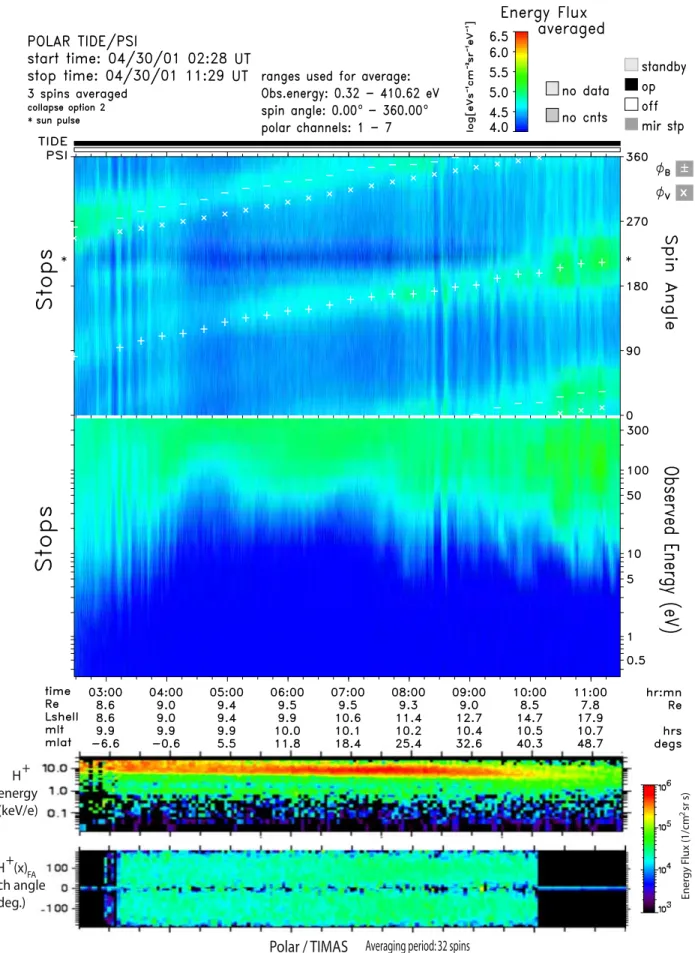
[20] When the Polar satellite was launched in 1996, it provided an even better opportunity to characterize the near-Earth low-energy magnetospheric plasma. The combination of the Thermal Ion Dynamics Experiment (TIDE) and the Plasma Source Instrument (PSI) presented the unprecedented prospect of detecting very low energy ions without the interference of spacecraft charging [see Moore et al., 1995]. [21] Figure 4 is an example of a TIDE spectrogram from a polar apogee pass through the afternoon sector while PSI is operational, effectively neutralizing the Polar spacecraft potential. The spacecraft orbit is displayed beneath the
spectrogram. This pass is typical in terms of the basic plasma characteristics observed as Polar traverses this region. Bidirectional field-aligned ions are seen counter-streaming equatorward of the cusp (0245 to 0500 UT). The energy range of these bidirectional flows is between 1 eV and 400 eV, the upper limit of the instrument detection range and there was no ion mass discrimination in the measurements.
[22] At 0600 UT the instrument encounters the cusp/cleft where large fluxes of ions are observed heated to tens of eV and beyond. At about 0900 UT the spacecraft exits the cusp/ cleft and continues over the north polar cap at high altitudes. In this region, single field-aligned outflows are observed in the 10 eV range. As the spacecraft altitude decreases, the ion energy drops to around 5 eV. These flows are all drifting slightly away from the field-aligned direction toward the antiram direction, indicating that the plasma has a greater tailward drift than the Polar orbital velocity and is overtak-ing the spacecraft on its way out to the tail lobes.
[23] TIDE data from apogee passes (near 9 RE) of the Polar spacecraft in late spring and early summer of 1997 and 1998 were examined in detail. During this time Polar was in approximately a noon-midnight orbit with about half of the passes traversing the dayside in the afternoon sector (12.8 – 14.7 MLT) and half of the passes crossing the morning sector (9.3 – 10.8 MLT). All of the TIDE data were taken while the PSI instrument was operational and effec-tively neutralizing the spacecraft potential. This enabled TIDE to measure ions with energies near 1 eV up to about 400 eV. TIDE typically observed bidirectional field-aligned flows on the dayside, equatorward of the cusp, followed by strictly upflowing plasma across the polar cap. The lower limit in energy of the dayside (precusp) populations was typically less than 1 eV increasing with magnetic latitude to about 10 eV. The upflowing polar cap flows were typically centered around 10 eV. In this collection of orbits, bidirec-tional field-aligned flows were observed in the precusp section of all of the morning side passes and approximately 50% of the afternoon passes. Single field-aligned outflows were always observed at higher invariant latitudes, consis-tent with the RIMS observations in Figure 2. These upflow-ing ions were seen to decrease in energy as the spacecraft altitude decreased. This suggests that the ions were gaining energy as they traveled upward and making the transition from polar wind to ‘‘lobal wind’’ [Liemohn et al., 2005].
4. TIDE Occurrence Probabilities of Bidirectional Field-Aligned Ions, 2001 – 2002 Data
[24] Motivated by a desire to understand the location characteristics of the bidirectional field-aligned distribu-tions, we chose to examine a 12 month period of TIDE data in 2001 and 2002. In the years following launch, the line of apsides of the Polar spacecraft orbit rotated toward the equator such that by September 2001, the line of apsides lay near the magnetospheric equator in the midnight sector. This gave us the opportunity to look at the bidirectional field-aligned distributions along the magnetic field line for large portions of the orbit. Magnetic activity was low during this survey, with over 88% of the data acquired while Kp was less than or equal to 3. Since the ISEE survey (see Figure 1) took place 22 years earlier, our observations fell Figure 3. The warm plasma cloak. A schematic equatorial
view of the warm plasma cloak population. The darker region illustrates the higher probability of occurrence of the bidirectional field-aligned ions in the prenoon versus postnoon sector. The cloak of warm ions is draped around the cold plasmasphere that is closer to the Earth.
during the same portion of the solar cycle as those published by Nagai et al. [1983].
[25] In order to get complete local time coverage of these distributions, we examined TIDE data from orbits of Polar
between 15 March 2001 and 15 March 2002. This group of 436 orbits covered all local times beginning and ending at 1200 MLT. Although this orbital configuration is optimal for observing the bidirectional field-aligned distributions Figure 4. Spectrogram of TIDE STOPS data taken during a Polar apogee pass over the afternoon sector.
PSI is operational during the entire pass. The top panel displays spacecraft spin angle versus time with ion energy flux indicated by color. The white plus and minus signs indicate the positive and negative local magnetic field direction, while the white crosses indicate the spacecraft ram direction. The bottom panel displays observed ion energy in eV versus time. Beneath the TIDE spectrogram is a plot of the Polar spacecraft orbit for this pass.
along the L shells, it is limited in its coverage of L shells less than about 6.5 in the portion of the orbit away from perigee. Hence, the statistics on L local time cover a range of L shells beginning at higher L than the studies mentioned previously, and the sampling at magnetic latitudes near the equator is restricted to geocentric distances greater than about 6 RE. In addition, because of contamination in the instrument from penetrating radiation belt particles, the data set is restricted to regions of the magnetosphere beyond the outer zone, again limiting the measurements of the lower L shells of the inner magnetosphere.
[26] Figure 5 shows an example orbit in November of 2001 in which the spacecraft moved in the L shell range of 9 – 10 for a significant portion of the orbit in the 19 – 20 MLT sector. The bidirectional field-aligned distributions stretch from 0030 UT at about 10 degrees magnetic latitude to 1100 UT at +30 degrees magnetic latitude. The spread in angle of the ion distributions around the magnetic field is seen to be about ±45 degrees as the spacecraft crosses the equator at 0200 UT and then broadens as the spacecraft moves toward the higher magnetic latitudes at 0600 UT. Some of the ions are seen to mirror beginning at 0900 UT. The apparent energy range of these distributions is from 1 eV to 400 eV with most of the ions in the 5 – 400 eV range. The PSI instrument is not operating during this time period, so we expect the positive spacecraft potential to prevent the entry of ions with energies below about 5 – 10 eV. The measured energy scale of the spectro-gram will also be reduced by the amount of the spacecraft potential. In this example, the double field-aligned distri-bution is seen to cover an L shell range of 7.0 – 10.1. It is interesting to note the collocation of the double field-aligned distribution and the trapped ring current distribution in the middle panel as measured by the TIMAS instrument which is capable of detecting ions up to 32 keV on Polar. These two separate populations coexist on the same set of magnetic field lines. The ring current particles show a fairly isotropic distribution with two loss cones of about ±20 degrees, while the bidirectional field-aligned distribu-tions display a more magnetic field centric distribution which would mirror at an altitude of 1 – 8 Earth radii. This combination of ion distributions would produce the ‘‘zipper’’ distributions reported by Fennell et al. [1981], near geosynchronous orbit. In this particular orbit, the spacecraft moves along at a nearly constant L shell and local time for close to 4 hours, from 0500 to 0900 UT. The spacecraft is approximately following a flux tube during this time period although the flux tube would be corotating with the Earth and would move past the spacecraft orbital plane. This allows one to see what could be interpreted as roughly the same distribution of warm plasma cloak ions broaden in pitch angle as the spacecraft descends and the ions begin mirroring near an altitude of about 8 Earth radii.
[27] Figure 6 shows another example of bidirectional field-aligned distributions in the evening sector, this time covering the L shell range of 8.0 to 9.8 between 1215 and 1730 UT. The angular spread of the ions around the magnetic field is again about ±35 degrees at the equatorial crossing at 1600 UT. In this case, the magnetic latitude coverage of 20 to +10 degrees is not as extensive as in the previous example although it is more centered on the magnetic equator. Note the collocation of the bidirectional
field-aligned distribution and the trapped ring current particles again in this evening local time example. The loss cone in the trapped ring current distribution can be seen to increase to ±20 degrees as the spacecraft moves away from the equator. The energy range of the bidirectional field-aligned ions is about 10 – 400 eV as contrasted to the ring current energies of a few to 30 keV.
[28] An example half-orbit pass from the morning sector is shown in Figure 7. The spread of the bidirectional distributions in this sector to much higher L shells is evident in this pass in which these distributions can be found from L = 9.2 at 0445 UT to greater than L = 18 around 10:00 MLT. The magnetic latitude coverage in this pass ranges from 6 to +50 degrees with an energy range of 10 – 400 eV. The angular spread of the distribution around the field direction is about ±35 degrees as the spacecraft crosses the equator at 0400 UT. The extent of the L shell range in which the bidirectional field-aligned distributions are found in the morning sector is significantly broader than the two earlier examples in the evening sector. As in the other two examples, the trapped ring current distribution is found to be colocated with the bidirectional distributions.
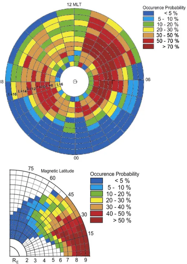
[29] For each of the orbits in the 1 year period, we examined the TIDE half-orbit summary plots which include both a spin-time and an energy-time spectrogram. We identified the time periods in which the bidirectional field-aligned distributions were observed on each orbit. These time segments were then accumulated into an L-MLT grid and a magnetic latitude-geocentric distance grid. The total number of occurrences in each grid space were divided by the total number of orbits that went through that space to get occurrence probabilities for TIDE/Polar to compare with the RIMS/DE and the PCE/ISEE data. These two plots are shown in Figure 8.
[30] The top panel of Figure 8 is similar in layout to the L local time plots in Figures 1 and 2. However, the coverage of this survey extends to much higher L shells than either the RIMS or ISEE results. The TIDE instrument also covers a wider energy range, reaching 400 eV. Nevertheless there are several striking similarities to the earlier surveys of bidirectional field-aligned ions. There is a similar band of significant occurrence probability at low L shells along the nightside. Then in the morning sector, until about 11 MLT, there is a very high occurrence probability out to much higher L shells. In Figures 1 and 2 it is impossible to tell how far out in L shell this feature extends. However, the TIDE data reveal that the occurrence of bidirectional field-aligned ions in the morning sector begins to drop off at about L of 16 in vicinity of the magnetopause. A reduced occurrence probability is also evident in the afternoon sector in Figure 8, mimicking the feature at L greater than 6 seen in the RIMS data. The main distinctive characteristic in the TIDE data is a higher occurrence frequency between 18 and 22 MLT at mid to high L shells, particularly right after 18 MLT. This could represent a slightly more energetic component of the warm plasma cloak or it could include counterstreaming auroral ions with a similar energy and pitch angle signature. In this portion of the TIDE data set, the different angular bins of the instrument are added together resulting in a coarser pitch angle distribution measurement that does not permit the measurement of the
small angle conics observed on ISEE by Nagai et al. [1983] or by Sagawa et al. [1987].
[31] The bottom panel in Figure 8 shows occurrence probabilities binned in magnetic latitude versus geocentric distance. Positive and negative magnetic latitudes are super-imposed to try to partially compensate for the incomplete
coverage provided by the spacecraft orbit during this time. The white segments are locations where there is no data available. This plot overlaps nicely with the bottom panel of Figure 2a and continues to higher altitudes. The warm plasma cloak is found at distances greater than 4 Earth radii and magnetic latitudes within ±60 degrees. This could easily Figure 5. Simultaneous observation of warm plasma cloak ions (bidirectional field-aligned ions) from
TIDE and trapped ring current ions from TIMAS. TIDE and TIMAS spectrograms are matched to the same time scale. The top TIMAS panel displays ion energy (integrated over pitch angle) versus time. The bottom panel displays pitch angle (integrated over energy) versus time.
be explained by assuming that these ions are reflecting between mirror points at each hemisphere. When the ions drop below 4 RE, their pitch angle distributions have broadened owing to the mirroring effect to the point where they no longer appear ‘‘field aligned.’’ Some of the ions may have in fact already magnetically mirrored and be
traveling in the opposite direction, though most field-aligned ions from the original bidirectional distribution may mirror at much lower altitudes. Even a highly focused distribution that is within ±10 degrees of the field-aligned or anti-field-aligned direction at 8 RE near the equator will Figure 6. Simultaneous observation of warm plasma cloak ions (bidirectional field-aligned ions) from
Figure 7. Simultaneous observation of warm plasma cloak ions (bidirectional field-aligned ions) from TIDE and trapped ring current ions from TIMAS in the morning sector.
Figure 8. Occurrence probability of low-energy (less than 400 eV) bidirectional field-aligned distributions plotted in (top) local time versus L shell and (bottom) magnetic latitude versus geocentric distance, with northern and southern hemispheres superimposed. Calculations are based on TIDE/Polar observations from 15 March 2001 through 15 March 2002. White areas are regions not covered by the spacecraft orbit or locations where the TIDE instrument was turned off.
evolve into a nearly isotropic distribution at altitudes less than about 4 REowing to parallel magnetic field gradients.
5. WPC Ion Distribution Characteristics
[32] As mentioned above, warm plasma cloak ions span a broad energy range, having been observed at a few eV by TIDE/PSI all the way up to several keV by EICS [Sagawa et al., 1987]. Within the energy range of the TIDE instru-ment (spacecraft potential to about 400 eV), the distribution
function is centered on the field-aligned direction, though often spread out in pitch angle with significant fluxes away from the B field direction with the pitch angle spread depending on the relative distance from the ions to their mirror point. Densities range from 0.5 to 3 cm 3and field-aligned velocities are typically 50 to 100 km/s. Parallel temperatures are generally 1.5 – 2 times larger than perpendicular temperatures.
[33] Figure 9 shows the moments of typical warm plasma cloak field-aligned (red) and anti-field-aligned (green) ions Figure 9. Moments of field-aligned (red) and anti-field-aligned (green) warm plasma cloak ions
observed by TIDE on the Polar spacecraft.
as observed by TIDE near Polar apogee, just before noon magnetic local time. In this example, the flow aligned with the magnetic field direction stays near 1 cm 3, while the anti-field-aligned population has a density that is higher and more varying. While ions flowing up from the southern hemisphere are traveling near 80 km/s in the magnetic field direction, the anti-field-aligned ions are noticeably slower at about 70 km/s. Parallel temperatures are consistently higher than perpendicular temperatures for both populations.
6. Trajectory Mapping
[34] In order to better understand the source and evolution of warm plasma cloak ions, ion trajectories were modeled using a three-dimensional steady state particle tracing code based on FORTRAN numerical procedures developed by Delcourt [1985] and Delcourt et al. [1988, 1989, 1993]. Outflowing ionospheric ions were tracked using guiding center approximations at low altitudes and full Lorenz-force calculations at altitudes above 2 RE geocentric. These calculations use the semiempirical Tsyganenko ’89 magnetic field model [Tsyganenko, 1989] and the Volland semiempir-ical, quasi-static electric field model [Volland, 1979] that assumes no parallel electric fields. The electric field model also contains a Heelis correction [Heelis et al., 1982] which models the general two-cell convection pattern that occurs during southward IMF. Both magnetic and electric fields are dependent on geomagnetic activity and are Kp driven in the trajectory calculations. They are valid representations of the magnetosphere only as a steady state first-order approxima-tion during southward IMF.
[35] For each ion trajectory, initial values of geocentric distance, local time, magnetic latitude, pitch angle, and ion energy were recalculated iteratively until the ion reached the boundaries of the model. The calculations were terminated if the ion encountered the magnetosheath or went lower than 0.1 RE or beyond 70 RE geocentric. More details of the software used for ion trajectory calculations are given by Huddleston et al. [2005].
[36] Polar wind and auroral ions were modeled starting at 5000km altitude using typically observed outflow energy and pitch angle characteristics for a given location in latitude and local time. For polar ions, the region of space covering all local times and invariant latitudes greater than 60 degrees was divided into 114 cells. From each cell four basic bounding limits were used as inputs for trajectory calculations: minimum energy-minimum pitch angle, minimum energy-maximum pitch angle, maximum ener-gy-minimum pitch angle, and maximum energy-maximum pitch angle. For more details on the grid of input parameters used for polar wind ions, see Huddleston et al. [2005, Figure 8]. Each ion was tracked by the trajectory code to determine its fate in the magnetosphere. Those trajectories resulting in ion behavior characteristic of the warm plasma cloak were then examined in detail.
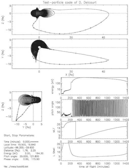
[37] Figure 10 shows the track for an H+polar wind ion that originates in the southern hemisphere polar wind at 5000km with 2 eV. As the ion drifts upward, it convects across the southern polar cap and gains about 10 eV in energy through ‘‘centrifugal acceleration’’ [see Cladis, 1986; Horwitz et al., 1994]. At this stage the ion appears as ‘‘lobal wind’’ [Moore et al., 2005; Liemohn et al., 2005]
and could represent the low-energy ‘‘beam’’ ions observed by RIMS (Figure 2b) and TIDE (Figure 4). Once the ion reaches the neutral sheet, it curvature drifts through the large cross tail potential and accelerates earthward having gained several hundred eV in energy. When it comes to within 5 to 10 RE of the Earth, the ion begins bouncing between hemispheres as it convects eastward around the Earth and loses energy. The ion also drifts outward in L shell and it terminates in the model magnetosheath before it reaches 17 MLT. This trajectory demonstrates how very low energy ionospheric ions can act as a source of warm plasma cloak ions that match observations.
[38] Figure 11 shows another example of a polar wind H+ ionospheric ion that forms the warm plasma cloak. Starting at 1.5 eV in the ionosphere, this ion gains several hundred eV as it enters the warm plasma cloak. It then convects out through the front of the magnetosphere just before noon local time. This ion reaches an L shell of about 16 by the time it leaves the warm plasma cloak.
[39] In general, the trajectories show that the warm plasma cloak ions drift to higher L shells as they drift past dawn. Then they move rapidly from an L of about 9 to an L of 15 at which point they exit the warm plasma cloak and enter the magnetosheath. This usually happens before the ion reaches noon local time. Trajectories show that only about a third of ionospheric ions convect eastward past noon. The rest drift outward in L shell and exit the cloak before 12 MLT. This would explain the observed decrease in occurrence probability of warm plasma cloak ions in the afternoon sector.
[40] In the trajectory mapping, all ions that form the warm plasma cloak have a nightside equatorial crossing distance that ranges from 8 to 45 REgeocentric, and the ions never exceed about 3 keV in energy. Ions originating in the high-latitude (>70 deg Inv Lat) dawnside (0 – 12 MLT) of the ionosphere convect eastward around the Earth and escape into the magnetosheath before 12 MLT. These ions all cross through the equator, usually in the magnetotail, on the dawnside (positive Y). Ions that originate in the low-latitude (<70 Inv Lat) dawn (0 – 12 MLT) or high-latitude (>70 Inv Lat) dusk (12 – 24 MLT) ionosphere display a mix of both dawn and dusk side crossings through the magnetotail. These ions generally convect through morning local times into the afternoon sector before they exit the WPC and enter the magnetosheath. Ions that originate in the low-latitude (<70 Inv Lat) dusk (12 – 24 MLT) typically stay confined to the premidnight sector from 18.5 and 21.5 MLT, mirroring between hemispheres and eventually convecting out to the magnetosheath (see discussion below).
[41] The trajectory mapping reveals that, while coming earthward from the magnetotail on the nightside, ions do not start to bounce and form warm plasma cloak ions until they reach L shells of about 10 or less. However, as soon as these ions drift around to the dayside, they move to higher L shells. This is consistent with ISEE, RIMS and TIDE observations showing an L shell outer boundary for occur-rence probability that is significantly lower on the nightside (Figures 1, 2, and 8).
[42] Figure 12 displays the specific ionospheric source regions in location, energy, and pitch angle for polar wind ions whose trajectories map to the warm plasma cloak. The numbers present in each cell identify which bounding limits
(listed below the map) of the outflowing polar wind distribution directly contribute to the warm plasma cloak. Empty cells represent locations where the polar wind ions that were modeled never became part of the warm plasma cloak, usually because the ions either precipitated into the conjugate ionosphere or remained at energies less than a few eV. From Figure 12 we see that the lowest-energy polar wind ions (in blue) only make it out to a large enough equatorial crossing distance to become the warm plasma cloak when they start in the high-latitude premidnight or isolated dayside regions of the ionosphere. More energetic (2 – 3 eV) polar wind (in orange) exiting the low-latitude dusk and isolated predawn high-latitude areas also contrib-utes to the warm plasma cloak. The full distribution of the
polar wind (in green) enters the warm plasma cloak when it originates at midlatitudes in the premidnight and predawn sectors or from high latitudes near noon.
[43] There are some notable exceptions to the general trends in the ion trajectories described above. Warm bounc-ing ions that enter into the region from 18 to 21 MLT tend to wander back and forth in MLT near dusk since they are caught near the separatrix of competing drifts from the sunward convection and the corotation electric fields. The trajectories for these ions show that as they move back and forth near dusk, they can have erratic changes in energy as they drift outward to the magnetosheath. These ions may contribute to the enhanced presence of bidirectional field-aligned distributions shown near dusk in Figure 8.
Figure 10. Trajectory of an H+ion that originates in the polar wind and contributes to the warm plasma cloak. The Z axis is aligned with the Earth’s magnetic north pole, the x axis points away from the Sun, and the y axis points toward dawn, completing a right-hand system. Plus marks along the ion trajectory indicate 10 min intervals, while diamonds indicate hour-long intervals. The start and stop parameters are given in the bottom left-hand corner of the plot.
[44] In addition to polar wind ions, auroral ions were also modeled with initial pitch angles ranging from 0 to 45 degrees. On the dayside, initial energies from 10 to 20 eV were used over the cleft region (70 – 80 degrees invariant latitude and 8 – 16 MLT). H+ ions originating below 75 degrees invariant latitude briefly joined the warm plasma cloak before entering the magnetosheath only if the initial energy was high enough (near 20 eV). However, most of the H+cleft ion fountain drifted directly into the magnetosheath without ever joining the warm plasma cloak. Nightside auroral ions were modeled over a region covering 60 – 70 degrees invariant latitude and 18 6 MLT and given an
initial energy of 500 eV. Most nightside auroral zone ion trajectories were found to precipitate in the conjugate hemisphere, directly drift out to the magnetosheath, or quickly exceed the energy range of ‘‘warm’’ plasma. How-ever, a small number of nightside auroral ions that started with 45 degree pitch angles formed bouncing convecting ions that were indistinguishable from the warm plasma cloak ions originating in the polar wind. The exact contri-bution of the auroral zone to the warm plasma cloak is difficult to quantify at this point, though it is expected to be smaller than that of the polar wind which originates from a much broader area of the ionosphere. This would be Figure 11. Trajectory of an H+ion that originates in the polar wind and contributes to the warm plasma
cloak. The Z axis is aligned with the Earth’s magnetic north pole, the x axis points away from the Sun, and the y axis points toward dawn, completing a right-hand system. Plus marks along the ion trajectory indicate 10 min intervals, while diamonds indicate hour-long intervals. The start and stop parameters are given in the bottom left-hand corner of the plot.
especially true during magnetically quiet times when the auroral outflow is reduced.
[45] Using the polar wind fluxes from Huddleston et al. [2005] and the ion trajectories given above, we can calcu-late the warm plasma cloak density that could be attained from the polar wind supply only. Using the total source flux from the different ionospheric grids that connect to the warm plasma cloak region (Figure 12), the approximate volume of the region and the average residence time that an ion spends in the warm plasma cloak region, we calculate a resulting polar wind-supplied warm plasma cloak density of
1 ion/cm3. This is in good agreement with the densities shown in Figure 9.
7. Ring Current Formation
[46] The modeling of ionospheric ion trajectories also revealed many cases where very low energy ions were transported out to the plasma sheet receiving sufficient energization from the cross-tail potential to eventually join the ring current. Figure 13 illustrates a typical example of the trajectory for one of these ions. The particle starts as a Figure 12. Source locations in the ionosphere (Inv Lat versus MLT, 5000 km altitude) for polar wind
ions that contribute to the warm plasma cloak. Regions colored in orange designate areas where only more energetic polar wind (2 – 3 eV) becomes the warm plasma cloak. Blue regions designate areas where only the lower-energy component of the polar wind makes warm plasma cloak ions. Areas in green identify where the full polar wind distribution acts as a source for the warm plasma cloak.
polar wind ion in the southern hemisphere with 0.5 eV and slowly drifts upward until it is centrifugally accelerated to about 8 eV. It continues through the tail lobes until it drifts into the neutral sheet more than 55 REfrom the Earth. At this distance, highly distended field lines in the tail cause the ion to drift through the cross tail potential and pick up kilovolts of energy. The ion then convects earthward, gathering over 10 keV through betatron acceleration. Once the ion comes within about 8 RE of the Earth on the nightside, it drifts westward and becomes part of the ring current. The pitch angle of the ion at this point is restricted
to angles around 90 degrees, indicative of ions in a ‘‘trapped’’ distribution.
[47] As with the warm plasma cloak ions, the ionospheric source of ring current particles came primarily from the polar wind and cleft ion fountain according to the trajecto-ries. Typically, upflowing ions originating in the auroral zone are more energetic [Huddleston et al., 2005] and are confined to auroral zone field lines, seldom drifting far enough out into the tail to receive the large energy necessary from the cross tail potential to transform them to ring current particles. There could certainly be some higher-Figure 13. Trajectory of an H+ion that originates in the polar wind and contributes to the ring current.
The Z axis is aligned with the Earth’s magnetic north pole, the x axis points away from the Sun, and the y axis points toward dawn, completing a right-hand system. Plus marks along the ion trajectory indicate 10 min intervals, while diamonds indicate hour-long intervals. The start and stop parameters are given in the bottom left-hand corner of the plot.
energy (keV) ions created in auroral processes that could contribute directly to the ring current when they drift to lower L shells in the nightside sector. Figure 14 identifies the various regions of the ionosphere which can furnish a supply of low-energy ions for the ring current as determined by ion trajectory mapping. The lowest-energy polar wind ions (in blue) originate in a source region near and just equatorward of the cleft region on the dayside, while more energetic few eV polar wind ions (in orange) come from the high-latitude premidnight sector and other isolated locations on the dayside. The full polar wind distribution (in green)
feeds into the ring current from local times between 13 and 16 MLT at invariant latitudes greater than 70.
[48] Trajectories show that these ring current supply ions have equatorial crossings in the magnetotail at geocentric distances greater than 20 REduring magnetically quiet times and greater than 15 REduring more active times when Kp is greater than 3. For some ions, the equatorial crossings can extend out to the limit of the model magnetotail at 70 RE. This distinguishes the trajectories for ions that join the ring current as opposed to those ions that become part of the warm plasma cloak. Warm plasma cloak ions pick up less Figure 14. Source locations in the ionosphere (Inv Lat versus MLT, 5000 km altitude) for polar wind
ions that contribute to the ring current. Regions colored in orange designate areas where only more energetic polar wind (2 – 3 eV) becomes ring current ions. Blue regions designate areas where only the lower-energy component of the polar wind makes the ring current. Areas in green identify where the full polar wind distribution acts as a source for the ring current.
energy while crossing the neutral sheet in the near tail region, from 8 to 45 RE, while ring current ions have neutral sheet crossings of 20 – 70 RE. After an ionospheric ion is energized in the tail, if it approaches the Earth with less than about 3 keV it will be driven primarily eastward by the corotation and sunward convection fields and will become part of the warm plasma cloak until it drifts to the magneto-sheath or is sent back across the poles into the magnetotail. However, if the ion energy exceeds 3 keV, it will curvature drift westward and become a ring current particle. These characteristics are summarized by the schematic shown in Figure 15. The simple ion circulation pattern shown in Figure 15 demonstrates how the warm plasma cloak ions would be more prevalent in the morning sector and would spread out to higher L shells in the late morning and early afternoon. It is also clear from Figure 15 why ions with equatorial crossings through the duskside magnetotail are more likely to drift past noon local time as predicted by the ion trajectory mapping.
[49] Ion trajectory calculations show that both the ring current and warm plasma cloak ion populations can occupy the same region of space, though at different energies, with the lower-energy warm plasma cloak ions tending to be more field aligned and mirroring at lower altitudes and the more energetic ring current being trapped closer to the equator (compare the examples in Figures 10 and 13). This is completely consistent with earlier observations [Fennell et al., 1981] and with the previously discussed simultaneous observations of warm bidirectional field-aligned plasma seen by TIDE and keV trapped ring current distributions seen by TIMAS (Figures 5, 6, and 7).
[50] It is recognized that the validity of the magnetic and electric field models used in the ion trajectory calculations decreases with increasing distance down the tail and that ion trajectories that cross the neutral sheet at larger downtail distances may be less accurate. As Figure 15 shows, the ionospheric ions which end up in the ring current are generated in a range of downtail distances beginning as close as 20 RE where the models are expected to be more
accurate and extending out toward the limit of the magne-tospheric field model. The trajectory model is expected to give a good first-order look at the ion motion and energi-zation in the tail. The polar wind contribution to the ring current particle population has been substantiated by recent work of Moore et al. [2005].
8. Discussion and Summary
[51] Continuing instrument capability enhancements in magnetospheric particle measurements have led to a retro-spective examination of low-energy ions with energies ranging from a few electron volts to hundreds of electron volts. Combining earlier observations from the ATS-5/6, ISEE-1, SCATHA and DE-1 spacecraft with recent meas-urements from the TIDE and TIMAS instruments on the Polar satellite, we have gained a new perspective on a region of plasma in the Earth’s middle magnetosphere: the warm plasma cloak.
[52] The warm plasma cloak is characterized by a bidi-rectional, field-aligned distribution of ions with an energy range of a few eV to greater than 400 eV. Ions with these characteristics are found just outside the plasmapause across the nightside and can extend from the plasmapause to the magnetopause on the dayside with occurrence probabilities approaching 100%. These double field-aligned ions are found more often in the morning sector than the afternoon sector. The spatial distribution of the warm ions draped around the plasmasphere on the nightside and being ‘‘blown’’ sunward by the convective wind in the magneto-sphere led to the ‘‘plasma cloak’’ designation. In a way, the morningside warm plasma cloak is the low-energy mirror analog to the duskside energetic ring current.
[53] The ions in the warm plasma cloak have their source in the ionosphere and are primarily formed through stepwise energization processes in the polar cap and magnetotail. Following energization in the magnetotail, the ions convect sunward into the middle magnetosphere beginning to bounce at L shells of 5 – 10 on the nightside and then Figure 15. A schematic showing how the plasma sheet crossing location of an outflowing ionospheric
drifting eastward around the Earth through the morning sector. As the ions bounce and drift through the morning sector, the bidirectional field-aligned distributions can be transformed to bidirectional conic distributions through charge exchange loss with the neutral atmosphere [Tinsley, 1976; Lyons and Moore, 1981; Sagawa et al., 1987]. Then, depending on the particle location and the strength of the convection field at the time of its transit through the dayside, the ion can be lost into the magnetosheath in the morning or afternoon sector.
[54] Surveys of low-energy ions with these characteristics have been done previously using the spacecraft mentioned above and have given very similar results. These surveys combined with more recent measurements from the TIDE and TIMAS instruments on Polar give a consistent picture of the warm plasma cloak region. The previous survey papers suggested mechanisms for the creation of these warm bidirectional field-aligned ions, but left uncertainty as to their origin in the ionosphere, auroral zone or plasma sheet. The primary difficulty with the explanations was that the plasma cloak ions are too energetic to be a direct upward extension of the ionosphere through the polar wind and not a clear result of upward flowing ions in the auroral zone which tend to precipitate in the opposite hemisphere and not form bouncing field-aligned ions with broad equatorial pitch angles as have been observed. These earlier explan-ations needed to have mechanisms either to energize the
polar wind ions or scatter the auroral outflowing ions in pitch angle so that they would become trapped [Horwitz et al., 1982a, 1982b; Nagai et al., 1983; Sagawa et al., 1987]. Fennell et al. [1981], in agreement with DeForest and McIlwain [1971], suggested that the lower-energy ions could drift in from the plasma sheet along with the higher-energy ring current ions with each group following different drift paths around the Earth. The energization process that has been suggested here is compatible with and is an expansion of this explanation.
[55] We suggest in this paper that the intermediate ener-gies of the warm plasma cloak ions can be obtained by a different process that causes the ion motion, not a direct upward acceleration of the ionospheric polar wind ions and not a pitch angle scattering of the already energized auroral ions, but a stepwise acceleration of the polar wind ions that carries them across the polar cap to the magnetotail and then back to the middle magnetosphere. As we have shown, detailed trajectory calculations using the three-dimensional model of Delcourt [1985] predict ion circulation and energization that is consistent with the observations.
[56] The circulation of ionospheric polar wind ions through the magnetosphere and their subsequent energiza-tion and contribuenergiza-tion to different magnetospheric plasma populations is summarized in Figure 16. Because of the obvious role that the ionosphere plays in populating most of the major regions of the magnetosphere, it is evident that Figure 16. Major plasma populations in the magnetosphere showing ionospheric origin and resulting
circulation patterns and energization.
future dynamic models of the magnetosphere must include an accurate, observation-based ionospheric input. This iono-spheric input combined with appropriate particle input from the solar wind can be expected to significantly enhance the accuracy of model predictions of magnetopheric behavior.
[57] Acknowledgments. This work involves collaborative research that has been done beginning at the NASA Marshall Space Flight Center more than 30 years ago. The authors are indebted to our many partners: Carl McIlwain and Sherman Deforest of UCSD for the ATS-5 and 6 data as well as Ed Shelley, Dick Johnson, Dick Sharp, and Bill Peterson at the Lockheed Palo Alto Research Laboratory for the ISEE, DE, and Polar data. The data analysis of Jim Horwitz, David Reasoner, Charles Baugher, Walter Lennartsson, and Tsugunobu Nagai has been pivotal in creating the early awareness of the warm plasma cloak region. We appreciate the support of the TIMAS, MFE, and TIDE instrument teams on Polar in making data available. One of us (C.R.C.) is grateful to NASA for the longstanding data analysis and instrument support that enabled the many collaborations between the Marshall Space Flight Center and the University of Alabama in Huntsville, the University of Texas at Dallas, and the University of Michigan and later with the NASA Goddard Space Flight Center, Vanderbilt University, and the Southwest Research Institute. This work was supported by NASA grant NNG04GB44G.
[58] Amitava Bhattacharjee thanks Michelle Thomsen for her assistance in evaluating this paper.
References
Baugher, C. R., C. R. Chappell, J. L. Horwitz, E. G. Shelley, and D. T. Young (1980), Initial thermal plasma observations from ISEE 1, Geophys. Res. Lett., 7, 657, doi:10.1029/GL007i009p00657.
Chappell, C. R., S. A. Fields, C. R. Baugher, J. H. Hoffman, W. B. Hanson, W. W. Wright, H. D. Hammack, G.R. Carignan, and A. F. Nagy (1981), The retarding ion mass spectrometer on Dynamics Explorer-A, Space Sci. Instrum., 5, 477.
Cladis, J. B. (1986), Parallel acceleration and transport of ions from polar ionosphere to plasma sheet, Geophys. Res. Lett., 13(9), 893, doi:10.1029/ GL013i009p00893.
Comfort, R. H., and J. L. Horwitz (1981), Low energy ion pitch angle distributions observed on the dayside at geosynchronous altitudes, J. Geophys. Res., 86, 1621, doi:10.1029/JA086iA03p01621.
DeForest, S. E., and C. E. McIlwain (1971), Plasma clouds in the magneto-sphere, J. Geophys. Res., 76, 3587, doi:10.1029/JA076i016p03587. Delcourt, D. C. (1985), Circulation des ions ionospheriques
suprathermi-ques dans la magnetosphere terrestre, Ph.D. thesis, Toulouse Univ., Toulouse, France.
Delcourt, D. C., B. L. Giles, C. R. Chappell, and T. E. Moore (1988), Low-energy bouncing ions in the magnetosphere: A three-dimensional numerical study of Dynamics Explorer 1 data, J. Geophys. Res., 93, 1859, doi:10.1029/JA093iA03p01859.
Delcourt, D. C., C. R. Chappell, T. E. Moore, and J. H. Waite Jr. (1989), A three-dimensional numerical model of ionospheric plasma in the magne-tosphere, J. Geophys. Res., 94, 11,893, doi:10.1029/JA094iA09p11893. Delcourt, D. C., J. A. Sauvaud, and T. E. Moore (1993), Polar wind ion dynamics in the magnetotail, J. Geophys. Res., 98, 9155, doi:10.1029/ 93JA00301.
Fennell, J. F., D. R. Croley Jr., and S. M. Kaye (1981), Low-energy ion pitch angle distribution in the magnetosphere: Ion zipper distributions, J. Geophys. Res., 86, 3375, doi:10.1029/JA086iA05p03375.
Giles, B. L. (1993), Inner magnetosphere circulation of thermal ions inferred from observed pitch angle distributions, Ph.D. thesis, Univ. of Ala. in Huntsville, Huntsville.
Giles, B. L., C. R. Chappell, T. E. Moore, R. H. Comfort, and J. H. Waite Jr. (1994), Statistical survey of pitch angle distributions in core (0 – 50 eV) ions from Dynamics Explorer 1: Outflow in the auroral zone, polar cap, and cusp, J. Geophys. Res., 99, 17,483, doi:10.1029/94JA00864. Heelis, R. A., J. K. Lowell, and R. W. Spiro (1982), A model of the
high-latitude ionospheric convection pattern, J. Geophys. Res., 87, 6339, doi:10.1029/JA087iA08p06339.
Horwitz, J. L. (1980), Conical pitch angle distributions of low energy ion fluxes at synchronous orbit, J. Geophys. Res., 85(A5), 2057, doi:10.1029/ JA085iA05p02057.
Horwitz, J. L., and C. R. Chappell (1979), Observations of warm plasma in the dayside plasma trough at geosynchronous orbit, J. Geophys. Res., 84, 7075, doi:10.1029/JA084iA12p07075.
Horwitz, J. L., C. R. Baugher, C. R. Chappell, E. G. Shelley, and D. T. Young (1982a), Conical pitch angle distributions of very low-energy ion fluxed observed by ISEE 1, J. Geophys. Res., 87(A4), 2311.
Horwitz, J. L., W. K. Cobb, C. R. Baugher, C. R. Chappell, L. A. Frank, T. E. Eastman, R. R. Anderson, E. G. Shelley, and D. T. Young (1982b), On the relationship of the plasmapause to the equatorward boundary of the auroral oval and to the inner edge of the plasma sheet, J. Geophys. Res., 87, 9059, doi:10.1029/JA087iA11p09059.
Horwitz, J. L., C. W. Ho, H. D. Scarbro, G. R. Wilson, and T. E. Moore (1994), Centrifugal acceleration of the polar wind, J. Geophys. Res., 99, 15,051, doi:10.1029/94JA00924.
Huddleston, M. M., C. R. Chappell, D. C. Delcourt, T. E. Moore, B. L. Giles, and M. O. Chandler (2005), An examination of the process and magnitude of ionospheric plasma supply to the magnetosphere, J. Geo-phys. Res., 110, A12202, doi:10.1029/2004JA010401.
Kaye, S. M., E. G. Shelley, R. D. Sharp, and R. G. Johnson (1981), Ion composition of zipper events, J. Geophys. Res., 86, 3383, doi:10.1029/ JA086iA05p03383.
Lennartsson, W., and D. L. Reasoner (1978), Low-energy plasma measure-ments at synchronous orbit, J. Geophys. Res., 83, 2145, doi:10.1029/ JA083iA05p02145.
Liemohn, M. W., T. E. Moore, P. D. Craven, W. Maddox, A. F. Nagy, and J. U. Kozyra (2005), Occurrence statistics of cold, streaming ions in the near-Earth magnetotail: Survey of Polar-TIDE observations, J. Geophys. Res., 110, A07211, doi:10.1029/2004JA010801.
Lyons, L. R., and T. E. Moore (1981), Effects of charge exchange on the distribution of ionospheric ions trapped in the radiation belts near syn-c h r o n o u s o r b i t , J . G e o p h y s . R e s . , 8 6 , 5 8 8 5 , d o i : 1 0 . 1 0 2 9 / JA086iA07p05885.
Moore, T. E., et al. (1995), The thermal ion dynamics experiment and plasma source instrument, Space Sci. Rev., 71, 409, doi:10.1007/ BF00751337.
Moore, T. E., et al. (2005), Plasma sheet and ring current formation from solar and polar wind sources, J. Geophys. Res., 110, A02210, doi:10.1029/2004JA010563.
Nagai, T., J. F. E. Johnson, and C. R. Chappell (1983), Low-energy (less than 100 eV) ion pitch angle distributions in the magnetosphere by ISEE 1, J. Geophys. Res., 88, 6944, doi:10.1029/JA088iA09p06944. Reasoner, D. L., C. R. Chappell, S. A. Fields, and W. J. Lewter (1982),
Light ion mass spectrometer for space-plasma investigations, Rev. Sci. Instrum., 53, 441, doi:10.1063/1.1136986.
Sagawa, E., A. W. Yau, B. A. Whalen, and W. K. Peterson (1987), Pitch angle distributions of low-energy ions in the near-Earth magnetosphere, J. Geophys. Res., 92, 12,241, doi:10.1029/JA092iA11p12241. Shelley, E. G., R. G. Johnson, and R. D. Sharp (1972), Satellite
observa-tions of energetic heavy ions during a geomagnetic storm, J. Geophys. Res., 77, 6104, doi:10.1029/JA077i031p06104.
Shelley, E. G., R. D. Sharp, R. G. Johnson, J. Geiss, P. Eberhardt, H. Balsiger, G. Haerendel, and H. Rosenbauer (1978), Plasma composition experiment on ISEE-A, IEEE Trans. Geosci. Electron., 16, 266, doi:10.1109/TGE.1978.294560.
Shelley, E. G., D. A. Simpson, T. C. Saunders, E. Hertzberg, H. Balsiger, and A. G. Ghielmetti (1981), The energetic ion composition spectrometer (EICS) for the Dynamics Explorer-A, Space Sci. Instrum., 5, 443. Shelley, E. G., et al. (1995), The toroidal imaging mass-angle spectrograph
(TIMAS) for the polar mission, Space Sci. Rev., 71, 497, doi:10.1007/ BF00751339.
Stevens, J. R., , and A. L. Vampola (Eds.) (1978), Description of the Space Test Program P78-2 Spacecraft and Payloads, Rep. SAMSO TR-78-24, U.S. Air Force Space and Missile Syst., Los Angeles Air Force Sta., Los Angeles, Calif.
Tinsley, B. A. (1976), Evidence that the recovery phase ring current consists of helium ions, J. Geophys. Res., 81, 6793.
Tsyganenko, N. A. (1989), A magnetospheric magnetic field model with a warped tail current sheet, Planet. Space Sci., 37, 5, doi:10.1016/ 00320633(89)90066-4.
Volland, H. (1979), Semiempirical models of magnetospheric electric fields, in Quantitative Modeling of Magnetospheric Processes, Geophys. Monogr. Ser., vol. 21, p. 261, AGU, Washington, D. C.
C. R. Chappell, Vanderbilt Dyer Observatory, Department of Physics and Astronomy, Vanderbilt University, 1000 Oman Drive, Brentwood, TN 37027, USA.
D. C. Delcourt, Centre d’Etude des Environnements Terrestre et Plane´taires, Observatoire de Saint-Maur, CNRS, IPSL, 4 Avenue de Neptune, F-94107 St. Maur, France.
B. L. Giles, NASA Headquarters, Washington, DC 20546, USA. M. M. Huddleston, Harpeth Hall School, Department of Physics and Astronomy, Vanderbilt University, Nashville, TN 37235, USA.
T. E. Moore, Heliophysics Science Division, NASA Goddard Space Flight Center, Greenbelt, MD 20771, USA.
![Figure 2b shows the occurrence probabilities of observing single field-aligned ‘‘beams,’’ which would include low-energy auroral ions, cleft ion fountain ions, and polar and lobal wind ions [see Liemohn et al., 2005] with sufficient energy to overcome the](https://thumb-eu.123doks.com/thumbv2/123doknet/14796332.603970/5.918.105.816.102.597/figure-occurrence-probabilities-observing-fountain-liemohn-sufficient-overcome.webp)