Development of the Machine Shop Instruction
and the Stirling Engine Project for 2.670: ME Tools
by
Stacy J. Morris
SUBMITTED TO THE DEPARTMENT OF
MECHANICAL ENGINEERING IN PARTIAL FULFILLMENT
OF THE REQUIREMENTS FOR THE DEGREE OF
BACHELOR OF SCIENCE IN MECHANICAL ENGINEERING
AT THE MASSACHUSETTS INSTITUTE OF TECHNOLOGY
JUNE 1996
(©1996 Stacy J. Morris. All rights reserved. The author hereby grants M.I.T. permission to reproduce
and to distribute publicly paper and electronic copies of this thesis document in whole or in part.
Signature of Author ... ...
Certified by ... ...
.. ... . f M echan ... .. ... ' Dep'nent of Mechanical Engineering
May 10, 1996 ... Douglas P. Hart assistant Professor Thesis Supervisor Certified by ... ...-... L-'.-.. ... ... Kevin N. Otto Assistant Professor Thesis Supervisor Accepted by . ... - . v .. - -- ... -.-.- , ...
-.'·, HSr r
/A;
UI'J/ · Professor Peter GriffithDevelopment of the Machine Shop Instruction
and the Stirling Engine Project for 2. 670: ME Tools
by
Stacy J. Morris
Submitted to the Department of Mechanical Engineering on May 10, 1996
in partial fulfillment of the requirements for the
Degree of Bachelor of Science in Mechanical Engineering
ABSTRACT
A new class called 2.670: ME. Tools, was added to the undergraduate Mechanical Engineering curriculum in 1995. 2.670 is only offered during I.A.P. and is intended for sophomore students. The purpose of the course is to provide an introduction to machining in the Pappalardo Lab and the Lab for Manufacturing and Productivity, and to engineering computer skills on Project Athena.
In June 1995, the development 2.670: M.E. Tools began, and in less than seven month;, the first class met, on January 8, 1996. This thesis will cover the development of the curriculum and instruction for the machining half of the class, as well as the development and production of the student project, a miniature Stirling Engine.
Thesis Supervisors: Douglas Hart, Assistant Professor of Mechanical Engineering Kevin Otto, Assistant Professor of Mechanical Engineering
ACIKNOWLEDGMENTS
I sincerely thank everyone who gave me their help, time and advice during this entire last year of planning. Thanks for making 2.670 a resounding success!
Liv Galendez, my partner through thick and thin, thanks so much for everything, and best of luck, you're terrific to work with! Federico Frigerio, thanks for all your help and for keeping me sane throughout all of January. Phil Houdek, thanks for all the last minute drawings and the engine advice.
Kevin Baron, thank you for taking the time to explain everything, for all your help and advice, and for always believing we'd somehow pull it all off!!
Fred Cote, thank you for helping with the Building 35 process plans (and telling me their origin) and for the lever shafts. Jerry Wentworth, thank you for the alcohol caps, and for the first working M.I.T. Stirling Engines. Norm Berube, thank you for all your help with the Building 3 process plans, and for innumerable parts. Norm MacAskill, thanks for all the cheer! Bob Nuttall, thanks for always asking me why I'm still in lab. Wayne Bidstrup, thanks for always stopping by to check things out. Dick Fenner, thank you for all your help and for giving me the key to the Pappalardo Lab!
Roger Howes, at the Thayer School of Engineering, at Dartmouth University, thank you for all of your advice and help.
Peggy Garlick, thank you very much for helping us track down the students to register, and for all your support throughout the class and at all other times!! Maureen DeCourcey, thank you for helping us order everything.
The students of the first session of 2.670, thank you for being cooperative when I suggested you come to class on a snow day! And to the students of both sessions, thank you so much for your patience with all the little bugs in the class, and for your wonderful suggestions on how to improve it!
The Undergraduate Assistants, thank you for volunteering so many hours of your own I.A.P. time to help us out and to help make 2.670 a success!
Doug Hart and Kevin Otto, thank you both so much for all your support, guidance and patience, for everything you've taught me, and for being a great pair of people to work for!
Lastly, I would like to dedicate this thesis to my parents, Steve and Nancy Morris. Thank you both so much for your endless supply of encouragement!!!
TABLE OF CONTENTS
1. Introduction . . . 7 1.1 Origin ... 7...7 1.2 Goals ... 7 1.3 Instruction .. . . . 7 1.3.1 Computer Lab . . . 7 1.3.2 Machine Shop ... 8... 8 1.3.3 Stirling Engine .. ... ... 8 1.4 Requirements .. . . . 9 1.5 Schedule ... 9 1.5.1 Sessions ... 9 1.5.2 Groups ... 10 1.6 Registration . . . 122. The Project: A Miniature Working Stirling Engine ... 13
2.1 The History of the Stirling Engine . . . ... 13
2.2 The Origins of the Current M.I.T. Stirling Engine. . . . .14
2.3 The M.I.T. Stirling Engine ... 14
2.3.1 Alcohol Burner (#001) ... 15
2.3.2 Displacer Cylinder (#002). . . . 15
2.3.3 Cylinder Plate (#004) . . . .15
2.3.4 Power Cylinder (#005) and Power Piston (#006) . . . ... 15
2.3.5 Gudgeon Block (#007) . . . ... 15
2.3.6 Power Connecting Lever (#008), Lever Connector (#009), . . . 16
Levers 11 & 12 (#011, #012) 2.3.7 Lever Shaft (#010) and Levers 11 & 12 (#01 1, #012) ... 16
2.3.8 Levers 11 & 12 (#011,#012) ... .16
2.3.9 Connector Link (#013) .. . . . .. . . 16
2.3.10 Displacer Piston Rod (#014) ... 17
2.3.11 Transfer Piston Guide Bushing (#015) . . . ... 17
2.3.12 Main Bearing Bushings (#019, #020) . . . 17
2.313 Flywheel (#021) .. . . . 17
2.3.14 Bearing Plates (#022, 023) ... 18
2.4 The 2.670 Stirling Spin-Off Contest . . . .. 18
2.4.1 Winners of the 1996 Stirling Spin-Off . . . .. 18
3. The Machine Shop . . . 19
3.1 Division of Parts. . . . 19
3.2 Division of Part Processes and the Process Plans . . . .. 19
3.2.1 The 2.670 Process Plans . . . ... 20
3.2.2 The History of the 2.670 Process Plan . . . .... 21
3. The Machine Shop, cont.
3.3 Division of Students . . . .. . . 22
3.4 Division of Instructors . . . .. . . 23
3.4.1 Comments on Instructors during 1996 and . . . 25
Recommendations for Future 2.670 Classes 3.5 Recommended Changes to the M.I.T. Stirling Engine . . . 26
3.5.1 Alcohol Burner (#001) . . . 26
3.5.2 Displacer Piston (#003) ... 26
3.5.3 Displacer Cylinder (#002) and Cylinder Plate (#004) . ... 26
3.5.4 Power Connecting Lever (#008), Lever Connector (#009), .... 26
Levers 11 & 12 (#011, #012) 3.5.5 Lever Connector (#009) and Levers 11 & 12 (#011, #012) . . . . 27
3.5.6 Displacer Piston Rod (#014) . .. ... 27
3.5.7 Crank Web (#016) ... 27
3.5.8 Bearing Plates (#022, 023) ... .. ... 27
4. Preparation for the Course .. ... 28
4.1 Vendor Information . . . .. . . 28
4.2 The Stirling Engine Components . . . 31
4.3 Fasteners for the Stirling Engine . . . 33
4.4 The Student Tool Kit . . ... . . . . ... . . . .33
4.5 Tools Purchased for Use in the Pappalardo Lab ... 36
4.6 The Supplies ... 36
4.7 The Start-Up Supplies Supplies ... 36
5. Surveys . . . 39
5.1 Overall ... 39
5.2 Machine Shop ... ... 39
5.21 Pappalardo Lab . .... ... 40
5.22 Lab for Manufacturing and Productivity ... 40
5.3 Computer Labs . . . .. . . 41 5.31 XESS ... .... ... 41 5.32 Matlab . ... . . ...42 5.33 Pro/Engineer. . . . . .. . . 42 5.4 Safety . . . ... . . . . 42 5.5 Schedule . . . 43
6. The Course Manual ... 44
Table of Contents (for Course Manual) .. . . . . . 46
7. Conclusions and Recommendations .. ... . . 111
Appendix 1. Notification Memos . . . .112
TABLE OF FIGURES
The M.I.T. Stirling Engine .
The 2.670 Session Schedule, I.A.P. 1996 . The 2.670 Group Schedule, I.A.P. 1996 . The 1816 Stirling Engine .
The M.I.T. Stirling Engine.
The 1996 Beauty Contest and Stirling Spin-Off Winners Division of Student-made Parts Between Machine Shops. A Generic Process Plan.
The 2.670 Process Plans and Page Location in this Thesis . A 1920 Process Plan for Machining a Square Thread Nut . Division of Students between Machine Shops and Processes Division of Instructors between each Machine Shop . Vendor Information (A-L) .
Vendor Information (M-Z).
Information for the Stirling Engine Components. The Starting Materials for the Stirling Engine . The Finished Parts of the Stirling Engine. Information for the Stirling Engine Fasteners. Information for the Tool Kits .
The 1996 Tool Kit.
Information for the Student-Used Tools in the Pappalardo Lab Information for the Supplies
Information on the Start-Up Materials . Students' Self-Ratings . Figure 1. Figure 2. Figure 3. Figure 4. Figure 5. Figure 6. Figure 7. Figure 8. Figure 9. Figure 10. Figure 11. Figure 12. Figure 13. Figure 14. Figure 13. Figure 16. Figure 17. Figure 18. Figure 19. Figure 20. Figure 21. Figure 22. Figure 23. Figure 24. . 8 10 .11 13 14 18 19 20 · 20 21 .23 · 24 29 · 30 32 31 .31 34 35 33 37 38 . . . 38 39
1. INTRODUCTION
1.1 ORIGIN
2. 670: ME Tools was created during the revisions of the undergraduate curriculum
in 1995. The development of 2.670 started in June 1995. It was first taught during the Independent Activities Period (I.A.P.) of the 1995-1996 M.I.T. academic year, and was added as a required course to the undergraduate curriculum effective for the graduating class of 1998. It is the first required course at M.I.T. which is offered only during I.A.P. This thesis will cover what is required in the development and administration of the machine shop half of this course.
1.2 GOALS
The purpose of creating this new class was to provide students with the tools needed for interactive learning in their future classes. The new curriculum revisions sought to teach students with less straight lecture and more interaction between the faculty and the students. As this would require different skills on the part of the students,
2. 670:ME Tools was created to give the students a thorough introduction to several of the
tools necessary for an undergraduate education in the Mechanical Engineering Department at M.I.T.
1.3 INSTRUCTION
There are two distinct parts of 2.670, computer lab instruction and machine shop instruction. This thesis will address the issues concerned with the preparation for and the instruction in the machine shop (for information on the computer lab instruction, see Galendez [1]).
1.3.1 Computer Lab
In the computer lab, students were introduced to several of the computing programs available on the Athena system. They spent one day on an overview of Project Athena (the M.I.T. campus-wide computing system) and the World Wide Web, and one
day on XESS (the spreadsheet on Athena designed for science and engineering computing); the instruction for these first two days was in lecture halls, followed by homework assignments on Athena. The students then received instruction on Matlab and Pro/Engineer, for three days consecutive days each, in computer classrooms.
1.3.2 Machine Shop
On the first day of the class, the students were introduced to safety issues in both the shop and in engineering practice. Starting on the second day, they learned, throughout the course, how to use the drill press, the beltsand.:r, th,: bandsaw, the lathe, the vertical and horizontal mills. as well as how to read use tap/die and drill sizes, and how to layout (mark and scribe). They also observed the Cincinnati Millicron and the Daewoo Lathe. Both the Pappalardo Lab in Building 3 and the Lab for Manufacturing and Productivity (LMP) in Building 35 were utilized to teach the students.
1.3.3 The Stirling Engine
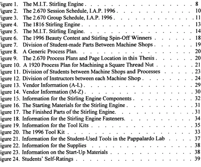
A Stirling engine was used as a teaching tool in both aspects of the course. In the machine shop, every student made slightly more than half the parts of a miniature
working Stirling engine, as shown in Figure 1. The students were provided with the other parts, and assembled and debugged their own engine. In the computer lab, students analyzed the Stirling engine in their Xess and Matlab homework assignments.
Figure 1. The M.I.T. Stirling Engine [2]
1.4
REQUIREMENTS
The students received six units of pass/fail credit for completion of the course. In order to pass, the students had to attend (or be excused from) all of the class hours, complete all homework (assigned during the World Wide Web, the Xess, and the Matlab sessions), and make all of the required Stirling engine parts. A working Stirling Engine was not a requirement; however, only three students were unable to get their engines running by the end of the class.
1.5 SCHEDULE
Due to the large number of students who needed to take the class (the maximum was set at 160 students), the class was split into two sessions of 80 students each, and within each session, the students were split into four groups of 20 students each.
1.5.1 Sessions
There were two sessions of 2.670 offered, each of which met for nine days over a two week period, with the second Monday as a day off (Martin Luther King Day during the first session). Session 1 met on 1/8/96 - 1/12/96 and on 1/16/96 - 1/19/96, and Session 2 met on 1/22/96 - 1/26/96 and on 1/30/96 - 2/2/96, as shown in Figure 2. Each day, the class met for eight hours, from 8 AM - 12 NOON and from 1 PM - 5 PM.
Figure 2. The 2.670 Session Schedule, I.A.P. 1996
1.52 Groups
Within each session, the students were divided into four groups (the students were assigned alphabetically). Two of these groups were in the machine shop in the morning and in the computer lab in the afternoon, and the other two were in the computer lab in the morning and the machine shop in the afternoon, as shown in Figure 3.
Each pair of groups met together during the first two days of computer instruction and then met separately for Pro/Engineer and Matlab instruction (three consecutive days of each). Similarly, they also met separately in the L.M.P. and the Pappalardo Lab (again, three consecutive days of each), until the last two days of class, when they both met in the Pappalardo Lab for assembly of the engines. In order to distinguish between the groups, each group was given a planet name (Mercury, Mars, Venus, Jupiter in Session 1, and Saturn, Uranus, Neptune, Pluto in Session 2).
10
Monday Tuesday Wednesday Thursday Friday Saturday Sunday
1/8 1/9 1/10 1/11 1/12 1/13 1/14
Session 1 Session 1 Session 1 Session I Session I no class no class
Day I Day 2 Day 3 Day 4 Day 5
first day of IAP
1/15 1/16 1/17 1/18 1/19 1/20 1/21
no class Session I Session I Session I Session I no class no class
[MLK Day] Day 7 Day 8 Day 9 Day 10
1/22 1/23 1/24 1/25 1/26 1/27 1/28
Session 2 Session 2 Session 2 Session 2 Session 2 no class no class
Day I Day 2 Day 3 Day 4 Day 5
1/29 1/30 1/31 2/1 2/2 2/3 2/4
no class Session 2 Session 2 Session 2 Session 2 no class no class
Day 7 Day 8 Day 9 Day 10
8 -9 AM 9 - 10:30 AM 10:30 -12 NOON I -3 Px 3 - P. 8 -12 NOON I - 5 P-M PaplroLb .PMtabPoEge
Introductionfor all groups
8 -12 NOON I - 5 P\M 8 - 12 \OON I - 5 PM1 8- 12 NOON I - 5 P\ 8 - 12 NOON I - 5 p\M 8 - 12 ooN - 3 Pr 3 -5 Pm ii
Pappalardo Lab (engine assemb i ::
j'""~'',~.'..I' I *, _ 01 j
Pappalardo Lab open to all four groupsforfinal engine assembl)
All four groups meet for final lecture and Pt Tau Sgma evaluations All four groups meet in Pappalardo Labfor the Stirling Spm Contest
Figure 3. The 2.670 Group Schedule, I.A.P. 1996
Day 1 Day 2 Day 3 Day 4 Day 5 Day 6 Day 7 Day 8 i Day 9 Day 10 I 1 | I _ _ _ I Illl I -- - -~~~~~~ I
1.6 REGISTRATION
As the first required class during I.A.P., there was no previously established protocol for registration for the class. For traditional I.A.P. classes, students informally register either late in the Fall Semester or on the first day of the class during I.A.P. However, as a required class with two separate sessions, session assignments (which affected many students travel arrangements) and the total number of students in each session had to be completed prior to the first day of the first session. In order to accomodate these needs, registration for the class was carried out on the World Wide Web during the first week of school in the fall semester. All advisors were sent letters (Appendix 1) notifying them to remind their sophomore students to register for the course. and the students were sent similar letters (see Appendix 1), as well as instructions for starting a web browser and registering for the class (see Appendix 1). The list of students who registered was checked against the list of sophomore students who were registered in October and November as "Course 2", and any "missing" students were notified and asked to register.
2 THE PROJECT: . MINIATURE WORKING
STIRLING ENGINE
2.1 THE HISTORY OF THE STIRLING ENGINE
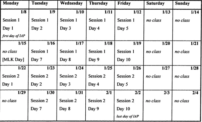
On September 27, 1816, Robert Stirling applied for a patent for an engine, as shown in Figure 4, at the Chancery in Edinburgh, Scotland. By trade, Robert Stirling was a minister in the Church of Scotland and he continued to give services until he was eighty-six years old. In his spare time, however, he built heat engines in his home workshop. Lord Kelvin used one of the working models during some of his university classes. In 1850, the simple and elegant dynamics of the engine were first explained by Professor McQuorne Rankine. Approximately one hundred years later, the term Stirling
engine was coined by Rolf Meijer in order to describe all types of closed cycle
regenerative gas engines.
Figure 4. The 1816 Stirling Engine [3]
Stirling engines are unique heat engines because their theoretical efficiency is nearly equal to their theoretical maximum efficiency, known as the Carnot Cycle
efficiency. Stirling engines are powered by the expansion of a gas when heated, which is followed by the compression of the gas when cooled. The Stirling engine contains a fixed amount of gas which is transferred back and forth between a "cold" end (often room temperature) and a "hot" end (often heated by a kerosene or alcohol burner). The "displacer piston" moves the gas be:ween the two ends and the "power piston" changes the internal volume as the gas expands and contracts.
2.2 THE ORIGINS OF THE CURRENT M.I.T. STIRLING ENGINE
The current M.I.T. Stirling Engine was first featured in an article in Popular
Science. It was developed at Dartmouth University by Roger Howes for use in an Thayer
School of Engineering class, ES 61 Thermodynamics. The class was first taught in the early eighties, and became a required class for engineering majors in 1994. Roger Howes estimated that at least 1 100 engines were built between the inception of the class and the spring of 1996.
2.3 THE M.I.T. STIRLING ENGINE
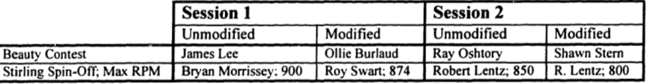
The Stirling engine was further adapted, during the Summer and Fall of 1995, to fit the needs of 2.670. Each part was designed to teach the students about a different aspect of machining. The final version of the engine is shown in Figure 5 (individual part drawings can be found on pages 70-105; page 65 contains a list of parts and numbers). This section will discuss the teaching benefits several parts of the M.I.T. Stirling Engine.
i
Figure 5. The M.I.T. Stirling Engine [4]
14
ir
2.3.1 Alcohol Burner (#001)
The alcohol burner consisted of a glass jar and a brass cap. The glass jar was used to store all of the fasteners which the students received. The brass cap was manufactured on the Daewoo Lathe, and had a groove cut for an o-ring. The use of an o-ring insured a tight fit with the glass jar, and showed the students how to obtain a leak-proof fit.
2.3.2 Displacer Cylinder (#002)
The displacer cylinder was silver-soldered, which prevented the application of extremely high temperatures (such as those generated by a blow-torch) at the hot end of the piston.
2.3.3 Cylinder Plate (#004)
This was made by the students in Building 3, where they used a jig to drill five holes in the face, and rounded two of the corners on the beltsander. Since the cylinder plate was made of brass and is 3/8" thick in the direction of drilling, the necessity of applying drilling fluid and "peck" drilling (backing the drill off) was readily apparent. The students traced rounded corners onto their piece, using blue die and a scribe, and then cut off the corners outside of the traced mark on the bandsaw. They finished off the curves on the beltsander, which gave them a feel for the hardness of brass.
2.3.4 Power Cylinder (#005) and Power Piston (#006)
These parts demonstrated Computer Numerical Controlled (CNC) programming and the rapid cycle time which is possible on the Daewoo Lathe.
2.3.5 Gudgeon Block (#007)
This is one of the more difficult parts which the students made on the lathe; because of its small size. After facing and turning the part and drilling a hole through the center on the lathe, the students used the horizontal mill to make the slot.
2.3.6 Power Connecting Lever (#008), Lever Connector (#009),
Levers 11 & 12 (#011, #012)
These were the first parts in Building 3 which used the drill press. Since the students used ajig to drill the holes in these levers, and since the levers were 3/16" or less thick, these were relatively easy pieces for students to start on, especially students with little machining experience. The students also rounded the end of each lever on the beltsander, which showed them the importance of holding a piece securely while using the beltsander.
2.3.7 Lever Shaft (#010) and Levers 11 & 12 (#011, #012)
Levers 11 and 12 were soldered to the lever shaft. Although this is not the strongest method of securing a joint, it allowed proper soldering technique to be introduced. Furthermore, it allowed easy adjustment of the angle between levers 11 and 12, which could compensate machining errors in other parts of the students' machines.
2.3.8 Levers 11 & 12 (#011, #012)
These two pieces were bent using a jig. The difficulties of bending metal were explained to the students, and concepts such as spring-back were experienced. They needed to separate levers 11 and 12 from the lever connector, which was determeined by the distance between the holes.
2.3.9 Connector Link (#013)
In drilling the holes of the connector link, the students scribed cross-hatches at the hole locations, and then used a center drill to start the hole. They had to drill all the way across the gap in order to insure that the holes lined up, and this drilling had to be done slowly in order to prevent the collapse of the top flange. The burrs created by drilling had to be filed in order to fit the corresponding pieces between the two flanges.
2.3.10 Displacer Piston Rod (#014)
The students finished the threads at one of the ends of this rod. Since the OD of the rod was only 1/8", the threads were started on the lathe in order to insure that they were aligned squarely. This showed the students the difficulty and importance of making the threads perpendicular to an axis.
At the other end of the rod, the students marked the location of the hole and drilled the hole through. Since the displacer piston rod was made of drill rod, it was absolutely necessary to center drill before attempting to drill the hole through the rod.
2.3l11 Transfer Piston Guide Bushing (#015)
This piece, which was made from hex stock, demonstrated that non-round pieces can be machined on lathes. Additionally, For best engine performance, the fit between the displacer piston rod and the transfer piston guide bushing needed to be as tight as possible, so the center hole of the guide bushing had tight tolerances. The students checked their finish by sliding the rod through the center hole of the guide bushing.
2.3.12 Main Bearing Bushings (#019, #020)
These purchased bearings were sintered bronze, which meant they could be reamed, if necessary. The students had to press-fit the bearings into the bearing plates. If the students hammered the bearings (which caused the bearings to flare out), or had a slight misalignment of the bearing plates, they simply reamed through both bearings, so that the crank web shaft coulc rotate freely.
2.313 Flywheel (#021)
This piece had very short shoulders which needed to be gripped on the lathes. Consequently, it showed the students the difficulties and hazards which can occur on the lathes, as flywheels which were not securely gripped could come out during operation of the lathe.
2.3.14 Bearing Plates (#022, 023)
These were the only pieces which the students used with the vertical mill. Due to time and machine constraints, they only used the mill to drill two holes, but this gave them exposure to the digital read outs, finding a precise location, as well as the operation of the vertical mill.
The students layed out two perpendicular lines on each bearing plate, and used the bandsaw to cut along the lines. They used the beltsander to round the corners, and as with the cylinder plate, this gave them a feeling for the hardness of aluminum.
2.4 THE
2.670
STIRLING SPIN-OFF CONTEST
A contest was held on the last afternoon of class. This included a "Beauty Contest" to determine the best-looking engines, and the "Stirling Spin-off' to determine the fastest engines. Certificates were awarded to winners in two categories, "modified" and "unmodified" engines. "Unmodified" engines were those which were made exactly according to the process plans, and "modified" engines were those which had any modifications from the process plans.
Since the class was developed as an introductory class, some of the students who had prior machine shop experience finished their parts more quickly, so they were encouraged to design and build modifications, such as heat sinks, to improve the efficiency of their engines.
2.4.1 Winners of the 1996 Stirling Spin-Off
Each session of 2.670 held its own Beauty Contest and Stirling Spin-Off; the winners of each are shown in Figure 6.
Session 1 Session 2
Unmodified Modified Unmodified Modified
Beauty Contest James Lee Ollie Burlaud Ray Oshtory Shawn Stern
Stirling Spin-Off; Max RPM Bryan Morrissey; 900 Roy Swart; 874 Robert Lentz; 850 R. Lentz; 800
Figure 6. The 1996 Beauty Contest and Stirling Spin-Off Winners
3. THE MACHINE SHOP
In order to meet the requirement of teaching 80 students machining skills in less than 36 hours over two weeks (twice). such that each student could successfully assemble an engine, the optimal schedule which would allow the most learning to take place had to be determined. This included determining the division of student-made parts between machine shops, the division of part fabrication and the "process plans" of each part in both machine shops, the student division between machine shops and within each machine shop, as well as the division of instructors.
As described in Section 1.5.2 Groups. within each session, the students were divided into four groups of twenty students each, so that, utilizing both machine shops in the morning and afternoon,on most days the maximum number of students in either machine shop was twenty students.
3.1 DIVISION OF PARTS
After deciding which parts would be made by the students, the parts were split between the two machine shops as shown in Figure 7.
Pappalardo Lab L.M.P.
Cylinder Plate (004) Gudgeon Block (007)
Power Connecting Lever (008) Transfer Piston Guide Bushing (015) Lever Connector (009) Crank Web (01 7)
Levers 11 & 12 (011, 012) Flywheel (#020) Connector Link (013)
Displacer Piston Rod (014) Bearing Plates (021, 022)
Figure 7. Division of Student-Made Parts between Machine Shops
3.2 DIVISION OF PART PROCESSES AND THE PROCESS PLANS
As mentioned above, the parts needed to be made by the students in such a manner as to minimize waiting time and maximize learning time.
3.2.1 The 2.670 Process Plans
The manufacturing of the parts was divided into separate processes, and process
plans were developed for each process by the author, in conjuction with Kevin Baron and
Fred Cote in the L.M.P, and with Norman Berube and Federico Frigerio in the Pappalardo Lab. A generic process plan is shown in Figure 8.
Figure 8. A Generic Process Plan
The process plans for each process, as listed in Figure 9, can be found in section 6. The
Course Manual, on pages 69-94.
Pappalardo Lab Process Plans L.M.P. Process Plans
Process Part(s) Invoved in Process Page Process Part Invoved in Process Page
3-A Cylinder Plate, Connector 69 35-A Transfer Piston Guide Bushing 85
Link, and Bearing Plates
3-B Bearing Plates 71-72 35-B Gudgeon Block 87-88
3-C Power Connecting Lever 75 35-C Crank Web 89,91
Lever Connector, and
Levers I1 and 12
3-D Cylinder Plate 77 35-D Flywheel 93,94
3-E Displacer Piston Rod 79
3-F Connector Link 81
3-G Cylinder Plate and 82
Bearing Plates
Figure 9. The 2.670 Process Plans and Page Location in this Thesis
20
Part Name Part Number Building part name here part number here X'
Material Start Size Process material of part here start size of part here
Op # Workplaces Tools Drawings Instructions and Parameters Complete
or Part (,check)
010 Machine or Tool or part Sketch for Detailed instructions and cautionary notes station for this name needed clarification of for each operation
operation for this this operation, operation as necessary
020 'In Building" and Process, X is either "3"for the Pappalardo Lab, or 35" for the L.M.P.
030
-In 'Process, N is a letter, which is used to
3.2.2 The History of the 2.670 Process Plan
The format of the process plans used in 2.670 was developed from a plan used in
2.86: Introduction to Manufacturing (now 2.008). The origins of this format, however,
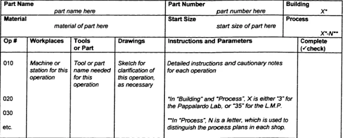
stretch back many years. As shown in Figure 10, plan organization by separation of operations, tools, and instructions was in use in 1910, the time of the first copyright of the
Textbook of Advanced Machine Tools [5].
SQUARE THREAD NUT 519
29. To make a Square thread nut, Fig. 27.
TAP I OtA. 5 THDS. TO t
To
A11 _nr
Fla. 27.- ScaEDu. I)na&tnar oF SQUAR, THREAD NUT. Specifications: Preparing nut blank. Rough threading. Tapping. Material, iron casting, cored; weight, 1 lb. 6 oz.
Hardnew, 29 to 31 (clerocope). Hligh-sped steel or stellite cutting tools.
Time: Study drawing and schedule in advance, 5 min. --Oil lathe, 4 -Bore, thrt-nd, and tap nut, 40 min.-Square, turn, and nurl nut, 2 min. - (All tools furnished.) Clean lathe, 3 min. -Total, I h. 20 min.
SCHEDULE OF OPERTIONS, IA(CIIINFS AND) TOOLS
Mount in chuck, true up and clamp hard in chuck. Rough sluare. (1), one or two
cuts. Feed inward. Rough bore hole to about
1.03', (2), two or three cuts.
Finish bore hole, (2), two or three cuts.
Or omit boring, bevel corner of hole and drill to size.
MACHLLVS, SPrF r, Fr. ims. Enrine lathe, 12 to 16'. 3d speed, or 20(o R.P.M. 2d or 3d speed, or 40 F.P.M. Hand or power feed. 1st or 2d speed, or 40 F.P.M. Medium power feed - 80 to 1'. 3d speed, or 60 F.P.M. fine power feed -140 to 1'. 2d or 3d spd, or 60 F.P.M. Toots. Independent chuck, chalk. Round-nose tool, or holder and cutter,
15' rake. Boring Lool, see p. 604.
Inside calipers, rule.
3 or 4-gronve high-speed steel twist drll (I.0-3';. S,'e p. 41n o:d Prtn.
, 1 . of tfte
' o,..
3.2.3 Recommended Changes to the Process Plans
The Drawings heading on the process plans should be changed to Photos, and
pictures of each step (as necessary) should be inserted. This was the original purpose of this column, but was implementation for the 1996 class was impossible due to time constraints. Additionally, perhaps reference numbers could be added for clarity to both the process plans and the part drawings, as in the process plan from 1920.
The process plans for each part should be reviewed each year following the completion of the course, and should be confirmed each year with the machine shop staff who will be helping with the instruction of the students. In particular, the process plans for the displacer piston rod should be revised to minimize accidental bending of the rod. As well, the process plan listed for the crank web has instructions for making the crank web from aluminum stock of 1.5" OD. In 1996, the students were actually given a part which was nearly completed on the Daewoo Lathe. The original process plan was left in this thesis in the event that the option of manufacturing the entire part is given to the students in a following year.
3.3 DiviSION OF STUDENTS
The division of the 160 students into eight groups of twenty (four groups per two-week session) allowed for a maximum of twenty students, in general, to be present in each machine shop. Additionally, the students worked with partners in both machine shops, which reduced the number of actual student operations to ten. As shown in Figure
11, the students were split into two groups on their first two days in the Pappalardo Lab, to adjust for the number of vertical milling machines, so each half of the students did the processes of the first two days in one of two possible orders, in the Pappalardo Lab. However, in the L.M.P., there were enough lathes to accomodate each pair of students, so the students went through all the processes in parallel, in the L.M.P.
Day 1 9- 10:30AM 10:30- 12 NOON I -3 PM 3 - 5 Pl Day 2 8 - 12 NooN I - 5 Pm Day 3 8 - 12 NooN I - 5 PM Day 4 8 - 12 NOON I -5 PM Day 5 8 - 12 NOON I -5 PM Day 6 Day 7 8 -12 NN I -5 PM Day 8 8- 12 NOON I - 5 PM Day 9 8-12 NOON I -5 PM Day 10 8- 12 NooN 3-5 PM Pappalardo Lab Instruction Introduction. Demos. SafetyLecture Introduction. Demos. SafetyLecture Introduction. Demos. SafetyLecture Introduction. Demos. SafetyLecture Processes 3-A & 3-B OR Processes 3-C. 3-D & 3-E Processes 3-A & 3-B OR Processes 3-C., 3-D & 3-E Processes 3-C. 3-D & 3-E OR Processes 3-A & 3-B Processes 3-C. 3-D. & 3-E OR Processes 3-A & 3-B Processes 3-F & 3-G Processes 3-F & 3-G Processes 3-A & 3-B OR Processes 3-C. 3-D & 3-E Processes 3-A & 3-B OR Processes 3-C, 3-D & 3-E
Max # Students 20 20 20 20 10 10 10 10 10 10 10 10 20 20 10 10 10 10 L.M.P. Instruction Introduction. Demos Introduction. Demos Introduction. Demos Introduction, Demos Process 35-B Start 35-A Process 35-B Start 35-A Finish Process 35-A, Start 35-D
Finish Process 35-A. Start 35-D Finish Process 35-D. 35-C Finish Process 35-D, 35-C Process 35-B Start 35-A Process 35-B Start 35-A Max Stude nts 20 20 20 20 20 20 20 20 20 20 20 20 NO CLASS
Processes 3C. 3-D & 3-E 10 Finish Process 35-A, 20 OR Processes 3-A & 3-B 10 Start 35-D
Processes 3-C. 3-D, & 3-E 10 Finish Process 35-A. 20 OR Processes 3-A & 3-B 10 Start 35-D
Processes 3-F & 3-G 20 Finish Process 35-D, 35-C 20
Processes 3-F & 3-G 20 Finish Process 35-D. 35-C 20 Engine Assembly 40 Open for fixing/remaking parts 40
Engine Assembly 40 Open for fixing/remaking parts 40
Final Assembly 80 Open for fixing/remaking parts 80
Stirling Spin-Off 80 0
Figure 11. Division of Students between Machine Shops and Processes
3.4 DIVISION OF INSTRUCTORS
With twenty students in each machine shop at one time, at least 4 instructors were needed in each machine shop, in order to have one instructor for every 5 students. This was accomplished by using two technical instructors in each machine shop, two
Undergraduate Assistants (UA's) in each shop, and assigning each professor to two of the groups in each session. The professors and the UA's remained with the same groups
!
l
-throughout each session, rotating between machine shops with the students. Additionally, there was a grad TA in the Pappalardo Lab, to assist with instruction on the vertical mill, and the author, who was one of the two Head UA's (the other Head UA, Liv Galendez, was in charge of the computer instruction) also remained in the Pappalardo Lab, in order to assist in the non-mill instruction and oversee the 2.670 office, which was located at one end of the Pappalardo Lab.
The recommended instructor load for each machine shop is shown in Figure 12, along a record of the instructors from 2.670, 1996.
Figure 12. Division of Instructors between each Machine Shop
24
RECOMMENDED DUTIES INSTRUCTORS DURING 2.670, 1996
INSTRUCTORS NAME TITLE
Pappalardo Lab
2 Technical Instructors Each at one of the three Dick Fenner General Manager vertical mills to instruct a pair Norman Berube Project Machinist of students.
2 TA's One at the 3rd vertical mill. Federico Frigerio Grad TA
(or I TA and One in charge of the "office", Stacy Morris Head UA (one of two) I Head UA) oversees non-mill processes,
and coordination of UA's.
2 UA's Rotate between shops with 1-2 undergrads UA students. In charge of a
particular process.
I Professor Rotates between shops with Doug Hart or Professor students, in shop as possible. Kevin Otto Professor
L.M.P.
2 Technical Instructors Oversee all the operations in Kevin Baron Technical Instructors
the L.M.P. Fred Cote Research Specialist
2 TA's Assist the techinical (none)
(or 1 TA and instructors in overseeing the I Head UA) LMP, and coordinate the
UA's
2 UA's Rotate between shops with 1-2 undergrads UA students. In charge of a
particular process.
I Professor Rotates between shops with Doug Hart or Professor students, in shop as possible. Kevin Otto Professor
3.4.1 Comments on Instructors during 1996 and
Recommendations for Future 2.670 Classes
The UA's in 1996 were volunteers from the M.I.T. chapter of Pi Tau Sigma (the Mechanical Engineering National Honor Society. They were juniors and seniors who had not taken the class before, and, unfortunately, time did not permit much instruction before commencement of the class. The UA's all put a great deal of effort into helping 2.670 run smoothly, and undoubtedly assisted a great deal in spite of not having had a chance to go over all of the process plans before the class started. Thus, undergraduate assistants in following years should probably be students who have taken 2.670 in a previous year (or who were UA's in a previous year), so that the necessary instruction of the UA's is minimal, and they can spend their time helping the 2.670 students instead of learning the process plans.
Each of the two professors, Doug Hart and Kevin Otto, were assigned to a morning and afternoon group, and as their schedules allowed, assisted in the instruction in the machine shop (they were each also involved with teaching parts of the computer instruction). They were both in the Pappalardo Lab throughout the entire day on Days 9 and 10, when more than twenty students were present for assembly.
The number of instructors in the Pappalardo Lab was sufficient to insure a 4:1 ratio of students:instructors at all times; however,. additional support in the L.M.P in the form of two TA's or a TA/Head UA combination, comparable to that in the Pappalardo Lab, is necessary to insure the same safe student/instructor ratio at all times in tile L.M.P. The author highly recommends ensuring that a Head UA is always stationed in the Pappalardo Lab, in order to deal with all the little things which will inevitably occur during the month of the course.
3.5 RECOMMENDED CHANGES TO THE M.I.T. STIRLING ENGINE
3.5.1 Alcohol Burner (#001)
Although the glass jar of the alcohol burner was extremely useful during production to store the fasteners, several of the jars were broken during the last couple days when students were walking around the shop with their engines in hand. This could be averted by providing each student with a piece of two-sided sticky tape or small pieces of Velcro with sticky tape on each side so that the jars could be securely fastened inside the indentation in the base.
3.5.2 Displacer Piston (#003)
These were manufactured out-of-house. The displacer piston could be improved by making it out of a material which would act more like a heat exchanger than brass.
3.5.3 Displacer Cylinder (#002) and Cylinder Plate (#004)
The four holes in the cylinder plate which support the bolts which attach the displacer cylinder should be adjusted slightly to form an exact square, so the displacer cylinder would have four possible orientations instead of only two.
3.5.4 Power Connecting Lever (#008), Lever Connector (#009),
Levers 11 & 12 (#011, #012)
These parts are made in Building 3 and use a jig for drilling the holes, which makes them great starting parts, especially for students with little machining experience. Unforttmately, because of the rotating schedule of students, the jig makes this process too simple for most of the students who come to Building 3 after Building 35. Students should be given the option to layout the holes and drill the holes using a vise, instead of using the jig, in order to teach them a little more about layout and drilling without jigs.
3.5.5 Lever Connector (#009), Levers 11 & 12 (#011, #012)
The distance between the holes is slightly different between the lever connector and levers 11 & 12. Since the lever connector is straight butlevers 11 and 12 are bent, a frequent mistake was the accidental bending of the lever connector. This could easily be remedied by adjusting the holes in each piece slightly so that all three pieces are identical and any two ef the three can be bent.
3.5.6 Displacer Piston Rod (#014)
A frequent problem during assembly was the discovery that the displacer piston rod had become bent. As the fit between the rod and the transfer piston guide bushing is critical to prevent air leakage, the rod must be perfectly straight. This should be emphasized at the start of the class, so the students know to take extra care while drilling the hole in one end and threading the other end.
3.5.7 Crank Web (#016)
The lathe work on this piece was done on the Daewoo Lathe, and students were handed the part to finish by drilling holes with a jig. If they are ahead of schedule in Building 35, students should have the option of making this piece from start, in order to give them more experience with the lathes.
3.5.8 Bearing Plates (#022, 023)
If time and machine availability permit, the students should use the mill to face one of the ends of the bearing plates, in order to get more experience on the vertical mill.
4. PREPARATION FOR THE COURSE
By the end of the Fall Semester, all of the components necessary to run 2.670 should be at M.I.T. There are several categories of materials which must be ordered; the engine components, the fasteners for the engine, the tool kit materials, extra tools for the machine shops, general supplies. In addition, there are a few necessary items which were purchased as start-up materials. Although these do not need to be purchased each year, they should be located prior to the end of the Fall Semester.
4.1 VENDOR INFORMATION
The materials for 2.670 were purchased from a variety of vendors during 1995. The current information for each vendor is listed in Figures 13 (A-L), and 14 (M-Z). In the following sections, vendors may be referred to only by the first part of their name.
Company Name Mailing Address Phone/Fax Contact Comments
Ace Trophy & 469 Wahington Street 617-542-2424 Dean They will print up
Atlantic Engraver Boston MA 02110-2409 name plates from a
[Downtown Crossing] list of registered
students. Admiral Metals 11 Forbes Road 617-933-8300
Service Center Co Woburn, MA 01801-2103 fax 617-932-3947
Automatic PO Box 3990 800-527-3091 Benjamin Does not accept 30
Tubing Co. 888 Lorimer Street Kaufman day terms for
Brooklyn, NY 11222-3990 payment for special
materials; requires check up front. Charles Casting PO Box 451 603-934-9370 Lincoln Does not accept
Franklin, NH 03235 Charles M.I.T. PO#;
requires check. Cole-Parmer 625 East Bunker Court 800-323-4340
Instrument Co. Vernon Hills, IL 60061 fax 708-647-7600
Dave Nugent 575 Province Rd 603-528-0141 David Does not accept L onia, NH 03246 (fax same) Nugent M.I.T. PO#;
requires check. Edgcomb Steel PO Box 260 603-883-7731
Brookline, NH 03033-0260
Home Depot 75 Mystic Avenue 617-623-0001 Somerville, MA 02145
Industrial 341 Second Ave 800-243-1343 Aluminum Waltham, MA 02154 fax 617-890-1343
Kaufman Co. Inc. 110 Second St. 617-491-5500 Dick Fenner should
Cambridge MA 02141 fax 617-491-5526 contact to arrange for the tools; the money for the tools is provided by Ford Motor Co. Kaman Industries A Street 508-752-1976
Auburn, MA 01501
LaVerde's Market Stratton Student Center 617-621-0733 Mech E Dept has a "standing PO" with LaVerde's.
Lehigh-Armstrong 12 Dunham Road 508-663-0010 Incorporated Billerica MA 01821-5727
L.S. Starrett Co. 121 Crescent St 508-249-3551 Donated Decimal
Athol MA 01331-1919 Equivalents and Tap
& Drill Sizes and Tools & Rules for Precision Measuring,
Kevin Baron should contact for donations.
Company Name Mailing Address Phone/Fax Contact Comments
McMaster Carr PO Box 440 908-329-3200
Supply Co. New Brunswick NJ fax 908-329-3772 08903-0440
Millard Metal PO Box 9054 617-848-1400 Bob Sena
Service Center Inc 116 Lindquist Drive fax 617-848-337? Braintree MA 02184-9054
M.I.T. Coop Kendall Square 617-499-3200
MSC Industrial 15 Cabot Road 800-753-7990 M.I.T. Account #
Supply Co. Woburn, MA 01801-1003 39577
North End 31 Harrison St. 617-542-2763 Does not accept
Fabrics Boston, MA M.I.T. PO#.
requires cash or check.
Physics MIT Room 4-355 617-499-3200 T. Coleman Accepts only M.I.T.
Stock Room five-digit account
number. Pills True 743 Massachusetts Ave. 617-876-8310
Value Hardware Cambridge, MA 02141
Small Parts Inc. 13980 NW 58th Court 305-558-1038 PO Box 4650
Miami Lakes FL 33014-3115
Valenite Inc. 750 Stephenson Highway Literature: Donated pocket
PO Box 3950 800-544-3336 protectors and
Troy, Ml 48007-3950 Tools: Handy Reference
800-488-8695 Guide, Kevin Baron
should contact for donations. VWR M.I.T. Rm. 18-B90 800-947-4270 x4250 Maddy
M.I.T. x31881
Walmart 343 Loudon Road 603-226-9312 Len
Concord, NH 03301 Morrill
Woolworths 350 Washington Street 617-357-5353 Boston MA 02108
[Downtown Crossing]
Zen Machine 1568 Steamboat Valley Rd 303-823-5842 Marty Gould
Shop PO Box 1658 (fax same)
Lyons CO 80540-1658
Figure 14. Vendor Information (M-Z)
4.2 THE STIRLING ENGINE COMPONENTS
For the 1996 sessions of 2.670, each of the parts of the engine were ordered and produced individually. Although plans are currently underway to have one vendor (Zen
Machine Shop) provide all of the parts as a single kit, the information for ordering the
parts individually is provided in Figure 15 for future reference. The starting materials of the kit are shown in Figure 16, and the finished parts are shown in Figure 17 (ready to be assembled). The total cost of all the parts, as listed, is $13398.89, which comes out to approximately $61 each for 220 kits.
Figure 16. The Starting Materials for the Stirling Engine [2]
0 V0000V ~0000 0000 0000 0
q c, 0 tn C= =W) 0 0C) Q C CI I r . C I r=CD CDO O C
U Q- ' I- 0 Jc-i 10 Cl0 \O I\1 I1 Iv I 0 I 0 IL I -Cl I -i0 Nr Cl0 ~ -0N ~- le Ic O0 N INIc00
U ; 10 1· 0 Clolo 1C o llo-i 00T 10 W) 4 0 r-:0C;C6 (6 C WI (\O I C I I M W I en en ldq I I o) I 0 0M c W) C) CO -c o V~- r - - V CC CD C Cl - 0 06 r~ 0 0 00 00 C -000 CD 0.- 000 " V 0 000 -- 'IOcl I 00 cl V
-'Tr CO g- Cl .UU1u) = U)" - = c 0o0J ) CD _0 09 C I ccc W WI
CO ~ O... CO " 0.1) 0 0 ) C OC OC C T h e Y, tn a C- M i M t n \o en 1 ) WI lc Co 4 4 cl l CO oo'ro 00000 " 10 C Cl a-- 0 r0CaI(l)l c~~~~~~~~~~~~~~~~~S I C ~~~~~~~~~~~~= -- A, d O~~~~~~~~ OQ00O0 I T It 0~ e, r ( r-t rl O o 4n (21 2Cl as a 0C C 0o C N 00I 0 - 0 :: 0r: C O a, 00 0000 0 0 0 U) I O -~ C COEE2 2 COC LZ> O C C . 0O
U) .noo U)~Z Z n e -o u o .U: nPIUIEI~ E ' 0 o C.C
a- = °. "O N
-CZ
-~~ID ~ Er rl I Ir I I IE E m ~ ~~~~~~ a t'", (~
16- 03~e ~-o 0
C O U)~~~~~~~C ~~~~~~00 CO O~~~~ Q ~
_Im CO CO, COJ~ CO COl~ 0J , 2 el c U e O~ %O M MI
3 6C CO m)C *COld _lcl cOCO oo M 0) 00 a- -~~~~~~~~X E mv, u10 m a rp lu 0 X Cn C) e n -- a Fq I -) -0- I c I I I I I I a en - t: - n M n ~~~~ - -~~~~~~~~~~I E~~~~~~~~~~~~~~ CZ x CZ _X Ln
E E-~~~~~~~~~~~~~~~-U E:UX~X I~f ~luC
-0 U OD tocC
0. CL U 72L~0 C OC'
0)0)1 MO ~ol, CO CO - 0)0 ) O C~ Olaa C1= C) D o 0 o Cro.
~~~~C Cl Cl' Cl C 0 0 o, 0 to . -. ,-L. C ,U.
4.3
FASTENERS FOR THE STIRLING ENGINEThe fasteners for the Stirling Engine were also all purchased individually. and were mainly provided to the students stored in the alcohol jar. Large excess quantities of the small fasteners should be purchased as these were easily lost on the floor. The information for ordering the fasteners is provided in Figure 18. The total cost for the fasteners, as listed, is $1089.66, or approximately $5 for each of the 220 kits.
4.4 THE STUDENT TOOL KIT
As part of the Stirling Engine Kit, the students also received a tool box with tools. These were mainly provided for the students by a generous donation from Ford Motor Company. In addition, some literature material was provided by Starrett and Valenite. As noted in Figure 13, Dick Fenner should contact Kaufman, Inc. in order to arrange for the tools. The information on the tools is shown in Figure 19, and the 1996 Tool Kit is shown in Figure 20. The total cost of the tool kit in 1996 was $7755.38, or about $35 for each of the 220 kits ($10 with Ford Motor Company's donation).
Mn N o mo tn W %O r- Sri cu ~ _ tm 00 X0 O. " O. O. O. o v, 4_v D£u 0 Nr t S mO O O - C4 N CU v 00 P N U 4n , m m , m : o ¢: :: , t', , m 0 00 0 0 0 0 0t CZ8 e x x x x x n O O x SI O -- o y. 8 e O O O O O O OQ O C O C5
co
IoT OO 0f CA O XoX W: v C r u=v n - -oo oql o o o oo o ot t. g .O/ ' / ' O r. O 0N O , \0 IA o0o 00 o . ._ _ 90 wnu O Or O, Or oO O, O, O Do _o O ( 4 x t t 4t k tt 4 4t 4t _ t _ PN 0 Z t s 2 Q 2 Q Q .j .j t0° 2 s _ III Q II Q Q UI v . . O Q ~<<<< < <~ 6 i .V
X _ _
_ t X N _ _ x
O _ _)
> E or of E oZ lr IE fo o1 o= o r o .o .s _ p x x n v, Ol On O rO x x188 00 X _ : I _ Rn o U _ - _ O Ch 0~~O O t en W ,-3A M 0 n° e (L1 X )= tcn V nna:. co oo v = X E E W0 0 - u~~~~~~~,~ ctO C'nU °~ n, y Cn C)n 0 ldd 0 g)0 ce ~. O m~~~~~~r i lld~~ ~ ~Ztnl &n Se U C: U (n cu ._ co -._ ullc n -o V)U MS. oo r-. coQ 0 CU - --- _ CN n e C1 C 0' c r el 0 0 CU 00 CZ0 0 d 4- c 0 C 0 0 4,~j t
~I-4.5 TOOLS PURCHASED FOR USE IN THE PAPPALARDO LAB
Most of the tools used by the students for their fabrication of the Stirling Engines were purchased by the staff in the machine shop and charged to 2.670. Some of the tools in the Pappalardo Lab, however, were kept at the "2.670 Office" at one end of the Pappalardo Lab. These purchasing information for these tools is listed in Figure 21. The total cost of these tools listed was $139.08, which is $.63 for each of the 220 kits.
4.6 THE SUPPLIES
There are many important supplies which were kept at the 2.670 Office, such as RTV, lubricant and thread locker, as well as the denatured alcohol, which was kept in safety bottles for the students to use. Additionally, posterboard was purchased in order to put signs up to help the students find the teaching locations, and many rolls of film were used to document the class. These supplies are listed in Figure 22. The total price of all of these supplies is $564.42, which is $2.56 for each of the 220 kits.
4.7 THE START-UP SUPPLIES
Finally, there were some necessary items which were purchased that will not be needed to be purchased every year. These items are listed in Figure 23, and should be located or purchased prior to the end of the Fall Semester. The start-up costs amounted to $2958.39, due to the high price of the casting patterns, which comes out to $13.50 for each of the 220 kits, but this cost will not recur each year.
0 L a. al0. 0 -o 0 c0 . om CA I--ac to -C 0. C: -C au L-C OC 6 .0U cJ Cu U) 0 0 r-eer 0 0 U0 73 :I u V) 7t -U m2 0 lu0 U) 0 S-z1.u 0 U) 0r a.. U Cu n qQ 9U C3 U) 0 0 0 0 :m u LI) v, U) z 0v U) U) 0, I-CEr. to i a 0 -It 5 QR U-: r 0 c .0u co V (9 en I-) co 00 4t U 0 2 z2 Cu 0 'Eel u I--7 Cun m 9 r) tt -, I-c "I oi O0 U U) Q 2U) U) c 0 U) CL 0 b Z xCu 0 n CC 1; 'C U-RC 1-C) U) (Orl 0U Itu, LO 2~ U) 0 CD CZ 1: th 0 D 1) F, ;n Ed n R D CN co (9 2 zU) 0 U) 'E co 0 10 z R T z Cm0 a.Ur 5 1)M: '-.)U) Cu CZ N L. . -L
L
o)*0 C 0 = D 0 0 oo 00 oo t- .o n Io 00' . I_ * O O` u -o . a, o o ,~ o o ,.. a ,o !c _ eq , ' .o _- .- ~ =-D C '" - _ - ,,_ 0 O 0. - Ie __0 _ _i
t
a 8 8 8.. u a a = a a 8 a 0 .a _ 0.0. 'I)r- C! ~ 0.r ~ _ u o ~ _ _ I 0O~~~0U)~t _~ ~ ~ u, ~ ~ I C C, .- CO~~~. ~U)O -. COCO0 CO- *-ZO g o. , cU I. oI~l~Olrooe-t a00e 0 Ir- (00 0 0r' [[-. o , o3 -, WI ) U) C.) CO 0 WICO C C C-; CO ~~~~~~~~~~~~~~~~~~,=. CO 00 rN~ V ao oa
CO Q 00le ~o 0 'c r ,- CO~~~~~~~~I CA 0 E Z CO cdc 00- a. 0* E~n CO . ) CO C O CU C \ CO CO 0.m =. 0 -. C* I-05. STUDENT SURVEYS
5.1 OVERALL
At the end of each session, the students were asked to fill out both the Pi Tau Sigma evaluation and a 2.670-specific survey (see Appendix 2). The students were asked to rate their knowledge of the machine shop and of each of the computer programs before and after the class, as shown in Figure 24.
Machine Shop Xess Matlab Pro/Engineer Session I Before 2.3 2.1 2.0 1.6 After 4.2 3.6 3.4 3.8 Change +1.9 +1.5 +1.4 +2.2 Session 2 Before 2.2 2.1 2.1 1.4 After 4.1 3.5 3.8 3.7 1 Change +1.9 +1.4 +1.7 +2.3 The rating scale was from I (no knowledge) to 5 (complete mastery).
Figure 24. Students' Self-Ratings
The students rated themselves on a scale of 1-5 and overall, rated themselves as most improved in Pro/Engineer, followed closely by machining, XESS and Matlab. The
improvements were nearly identical in both sessions for Pro/Engineer, machining and
Xess, but quite different in Matlab. Some changes were made between the first session and the second in the teaching of Matlab, due to the expressed dissatisfaction of several students during the first session.
The students had many thoughtful comments and suggestions for improvement in all areas of the course, which will be discussed in the remainder of this section.
5.2 Machine Shop
On the surveys, the students were asked to comment on each machine shop individually.
5.2.1 Pappalardo Lab
The students learned many new skills in the Pappalardo Lab, "Soldering, milling, sanding, drilling, scribing, tapping, and reaming. I think it wvil be extremely useful in the future." (2.1)1 Overall, students found the pace slow, but they liked being able to set their own pace. As one student wrote, "The pace was excellent - you made your own! For some people, there was too much time allotted for machining, but it was that extra time that gave me the freedom to go slow." (2.55) As described in Section 3, the pace was designed so that students with no prior machine shop experience would be able to successfully complete all of the tasks, and the option of heat sinks or other modifications was added for students who were a bit ahead. One student commented, "I also liked having a full extra day to do extra design and machining. The pace was slow, but we were able to do extra stuff so it was cool." (2.37)
Students suggested having the option to make more of the engine parts, or perhaps making the levers from stock instead of using the jigs. Many students expressed a wish to learn more about the milling machine, such as how to use an end-mill, or how to mill a slot, especially since there was so much extra time. Some students were frustrated by all of the jig work, while others appreciated seeing the precision and time-saving benefits of jigs.
5.2.2 Lab for Manufacturing and Productivity
The students were also exposed to many new skills in the LMP. One student proclaimed, "It was incredible. LMP taught me so much, I went in there expecting to seriously hurt myself and I came out know how to turn, to face, rill, tap, thread, shift gear, and band saw." (2.38) Overall, the pace was just right. Again, students liked being able to set their own pace, but were frustrated by the "bottlenecks" caused by having to wait to use the lathes and other machines.
All survey comments are numberd (X,Y). where X is the session number. and Y is the number of the survey. for reference purposes.
Most students appreciated that they made their parts with less help from jigs; one student philosophically wrote, "It seemed like the success of our actions depended on us a little more; fewer jigs, more room for error. Perhaps I learned a little more." (1.36) They also appreciated being shown how to set the lathes, "I learned how to set spindle speed and feed rate... Allowing us to play with those settings really took the mystery out of the machine." (2.28)
Students would have liked to have been allowed to have machined the crank web entirely from stock if they were ahead of schedule. The students loved seeing the CNC Daewoo Mill and Lathe, but would have liked to learn even more about these or even have a chance to try using them.
5.3 Computer Labs
As with the machine shops, students were asked to comment on each individual section of the computer instruction.
5.3.1 XESS
There were four very different views on XESS. Students who were already
familiar with a spreadsheet were either bored or enjoyed learning about the more complex applications of XESS. Students who were unfamiliar with spreadsheets were either lost or found it to be an excellent intro. Many students suggested adding more than one example in class, so as to introduce more basic/common applications, as well as having the
homework differ from the class examples, since most students learned mainly from doing the homework. In particular, students would have liked to have seen how to import data, and how they might use XESS in their future classes. After their Matlab course, several students viewed XESS as obsolete, and many wondered why XESS was taught instead of a more common application such as Microsoft Excel. Also, many students suggested teaching XESS in a computer cluster, so that students could follow along on computers during the lecture. A few students even suggested expanding the XESS instruction to two days.
![Figure 1. The M.I.T. Stirling Engine [2]](https://thumb-eu.123doks.com/thumbv2/123doknet/14744424.577681/8.915.282.624.733.966/figure-the-m-i-t-stirling-engine.webp)

![Figure 4. The 1816 Stirling Engine [3]](https://thumb-eu.123doks.com/thumbv2/123doknet/14744424.577681/13.906.316.584.515.742/figure-stirling-engine.webp)
![Figure 5. The M.I.T. Stirling Engine [4]](https://thumb-eu.123doks.com/thumbv2/123doknet/14744424.577681/14.906.216.680.609.915/figure-the-m-i-t-stirling-engine.webp)

![Figure 10. A 1910 Process Plan for Machining a Square Thread Nut [5]](https://thumb-eu.123doks.com/thumbv2/123doknet/14744424.577681/21.915.257.648.313.966/figure-process-plan-machining-square-thread-nut.webp)