To cite this document:
Pizarro, Francisco and Pascaud, Romain and Pascal, Olivier and
Callegari, Thierry and Liard, Laurent Evaluation of microplasma discharges as active
components for reconfigurable antennas. (2012) In: Antennas and Propagation (EuCAP),
2012 6th European Conference on, 26 March 2012 - 30 March 2012 (Prague, Czech
Republic).
O
pen
A
rchive
T
oulouse
A
rchive
O
uverte (
OATAO
)
OATAO is an open access repository that collects the work of Toulouse researchers and
makes it freely available over the web where possible.
This is an author-deposited version published in:
http://oatao.univ-toulouse.fr/
Eprints ID: 10031
Any correspondence concerning this service should be sent to the repository
administrator:
[email protected]
Evaluation of Microplasma Discharges as Active
Components for Reconfigurable Antennas
Francisco Pizarro, Romain Pascaud
Universit´e de Toulouse: ISAE, DEOS Toulouse, France
Email: [email protected]
Olivier Pascal, Thierry Callegari, Laurent Liard
Universit´e de Toulouse: UPS, INPT, LAPLACE CNRS: LAPLACE
Toulouse, France
Abstract—This paper presents an experimental setup for the
wideband RF characterization of plasma Micro Hollow Cathode Sustained Discharge (MHCD). This microdischarge is studied as a candidate for integrated active component in antennas, using the change of permittivity caused by the presence of plasma. The measurement setup consists of a 50Ω microstrip line with a single MHCD placed in its center. The measurement of the scattering parameters of the experimental device permits the evaluation of the complex permittivity and conductivity of the MHCD.
I. INTRODUCTION
Due to their physical characteristics, plasma discharges appear as interesting candidates in the research of new devices in the RF domain. A plasma medium is an ionized gas, with the particularity that it can behave as a low permittivity material or as a conductor with low conductivity at several frequencies, and under certain conditions. On the other hand, when the gas is not ionized (so the discharge is not present), the medium remains electromagnetically transparent, like vacuum. In fact, the complex permittivity of the plasma medium depends on the plasma density and collision frequency, which depend on the type of gas, its pressure and the power injected to the discharge.
The use of plasma discharges on the RF domain has been case of several studies. One example is the plasma filled tubes used as radiating elements [1], [2]. Good results in this topic have been obtained for a wide frequency range (500 MHz to 20 GHz) with efficiencies comparable to classic copper-wire antennas [3]. Other devices such as RADAR Transmit-Receiver tubes use also high power plasma discharges for their operation [4].
The possible control of the complex permittivity of the plasma discharge makes it interesting for RF components reconfiguration [5], [6]. Under this perspective, the Micro Hollow Cathode Sustained Discharge (MHCD) seems to be a good candidate for a possible integration in a RF printed circuit due to its small size (around 1 mm) [7].
Before using the MHCD in a RF circuit, it is necessary to characterize its complex permittivity behavior. A measuring device consisting of a 50 Ω microstrip line with a single MHCD placed in its center is proposed. This device permits the wideband evaluation (1 to 15 GHz) of the S parameters of the MHCD as a function of several parameters (gas pressure, electric current and applied voltage).
II. PLASMADISCHARGE A. Plasma characteristics
A plasma is an ionized gas, macroscopically neutral, with the characteristic of being a conducting medium. One way to create a plasma at ambient temperature is by applying an electromagnetic field to a gas. This will cause an acceleration of the free electrons present in the gas, providing the enough kinetic energy to produce collisions and so, ionize other molecules. This phenomenon, called avalanche breakdown, leads to the generation of an electric discharge and therefore, the formation of the plasma media.
One parameter that defines the type of plasma discharge is the ionization degreeδ defined as:
δ = ne ne+ n0
(1) whereneis the electron density andn0is the neutral density.
The MHCD device creates plasmas with low ionization degree, typically δ ≤ 10−3, that are called non-equilibrium plasmas.
Thus, this kind of plasmas allows heavy particles to keep their temperature close to room temperature whereas electron are warmed enough to ionize.
According to the Drude’s model, the complex permittivity ǫ of the plasma and so, the complex conductivity σ can be defined as: ǫ = 1 − ωp 2 ω2−jν p·ω (2) σ = ωp 2 ·ǫ0 ν2 p+ ω2 ·(νp−jω) (3)
where ω (rad/s) is the RF pulsation of the electromagnetic wave interacting with the plasma, νp the collision frequency
(s−1) andωp the plasma pulsation (rad/s) defined as:
ωp=
s ne·q2
ǫ0·me
(4) whereneis the electron density,q the electron charge and me
the electron mass.
As exposed in (2) and (3), the complex permittivity and conductivity of the plasma depend on the collision frequency and the electron density (both dependent on the type of gas, the
0000000000000 0000000000000 1111111111111 1111111111111 00000000000000 11111111111111 Φ Dielectric Anode 1 Anode 2 Cathode d
Fig. 1: Micro Hollow Cathode Sustained Discharge (MHCD) configuration.
gas pressure and the power injected to the discharge). There-fore, it is possible to control the electromagnetic behavior of the plasma medium, and modify the way it interacts with an incident RF electromagnetic wave.
B. Micro Hollow Cathode Sustained Discharge
Among the structures that enable the generation of non-equilibrium, the MHCD has several interesting characteristics for a possible integration in a RF planar circuit, such as its small size and the possibility to generate very localized discharges.
As shown in Fig. 1, the MHCD is a three electrode configuration discharge. On the first section of the device a very thin substrate (several hundred micrometers) is placed between two planar electrodes (Cathode and Anode 1), where a central cylindrical hole of diameter Φ is drilled between these three layers. The function of the dielectric layer is to electrically isolate these two electrodes. When a DC voltage is applied (several hundreds volts) between these two electrodes, a plasma discharge takes place inside the hole. Finally, a third electrode (Anode 2) is placed at a distance d (up to several millimeters) from the Anode 1. This electrode, when positively DC biased, pulls up the discharge and creates a larger volume plasma between the Anode 1 and the Anode 2 [8].
In order to characterize the interaction between a RF elec-tromagnetic wave and the plasma discharge generated between the Anode 1 and the Anode 2, a measurement device that includes a MHCD has been designed.
III. MEASUREMENTDEVICE
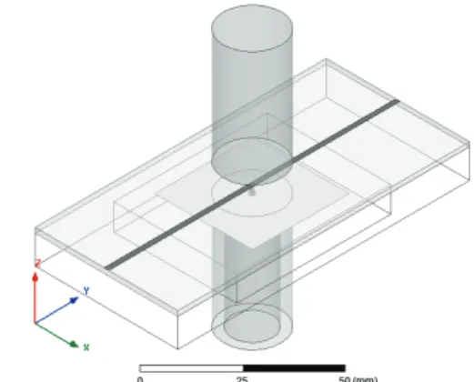
A 3D representation of the device is exposed in Fig. 2. The measurement device consists of a 50Ω microstrip line with a hole in its center where the plasma discharge takes place. Its objective is to measure the influence of the plasma discharge on the S parameters of the microstrip transmission line. The device configuration is exposed in Fig. 3. All the electrodes are made of copper, the microstrip line is made of gold and the dielectrics are made of alumina due to the high temperatures expected in the discharge area (around 900 K).
In addition to the three electrodes used for the MHCD generation, a RF section is placed on top of Anode 1 to characterize the discharge. It consists of a microstrip line etched on an alumina substrate with a hole of a diameter Φ at its center (Fig. 4). This hole is aligned with the hole of the MHCD configuration. Note that Anode 1 is also used as the RF ground plane for the transmission line, and also,
Fig. 2: 3D view of the characterization device
0000000000000 0000000000000 1111111111111 1111111111111 000000000000 000000000000 111111111111 111111111111000000 000 111 111 111 000 000 111 111 0000 0000 0000 1111 1111 1111 0000 0000 1111 111100 0 0 1 1 1 1 00 00 00 00 11 11 11 110000 0000 1111 1111 00 11 0011 0 1 00 00 00 00 11 11 11 11 0 1 0 100001111000001111100110101 000 000 000 000 000 111 111 111 111 111 X Z Φ Φcat Φan2 hal has han1 han2 hcat hdif Dielectric Dielectric Anode 1 Anode 2 Cathode d 50 Ω microstrip line
Fig. 3: Cut view of the measuring device.
000000000000000000000000 111111111111111111111111 X Y ǫr, tanδ Φ Wms Wal Lal Hole 50 Ω microstrip line
Fig. 4: Top view of the RF section.
that this configuration permits a separation of the DC and RF excitations. Finally, when the discharge is pulled up by the
Anode 2, it fills the hole placed under the microstrip line, and the plasma interacts with the RF electromagnetic field propagating along the microstrip line. This interaction can be evaluated by measuring the S parameters of the transmission line.
The final values of the device parameters are: Φcat =
20 mm ; hcat = 5 cm ; han1 = 11 mm ; hdif f = 1 mm ;
has= 600 µm ; Lal = 10 cm ; Wal= 5 cm ; hal= 1, 57 mm
; Wms = 1, 516 mm ; Φ = 1 mm ; d = 7 mm ; ǫr= 9, 9 ;
tanδ = 2.10−4,φan2= 20 mm ; han2= 5 cm.
The measuring device is finally inserted in a vacuum cham-ber, where the type of gas (argon, helium) and its pressure can be controlled.
1 2.5 5 7.5 10 12.5 15 −50 −40 −30 −20 −10 0 Frequency [GHz] |S11 | dB Air Metal n e 10 13 cm−3 ; ν p 10 12 s−1 n e 10 14 cm−3 ; ν p 10 12 s−1 n e 10 13 cm−3 ; ν p 3.10 10 s−1
Fig. 5: Simulated reflection coefficient for different micro-discharges 1 2.5 5 7.5 10 12.5 15 −15 −12.5 −10 −7.5 −5 −2.5 0 Frequency [GHz] |S12 | dB Air Metal n e 10 13cm−3 ; ν p 10 12s−1 n e 10 14 cm−3 ; ν p 10 12s−1 n e 10 13cm−3 ; ν p 3.10 10s−1
Fig. 6: Simulated transmission coefficient for different micro-discharges
IV. RESULTS
Several simulations (using Ansoft HFSS [9]) were done to study the influence of the plasma parametersωp andνpon the
S parameters of the line (Fig. 5 and Fig. 6).
Three different discharges were simulated considering ex-pected values forωpandνp [10]. It concerns two atmospheric
pressure (νp= 1.1012s−1) discharges with electron densities
of 1013
cm−3 and 1014 cm−3 (ωp = 1, 8.1011 rad/s and
5, 6.1011
rad/s respectively) and a low pressure discharge (νp = 1.1010 s−1) with an electron density of 1013 cm−3.
These discharges are compared with two reference cases: a metallic filled hole and an air filled hole.
As shown in Fig.5 and Fig.6, the behavior of the discharge depends on theωp/νp ratio. The results obtained with the
at-mospheric pressure discharges are similar to the ones obtained with the air filled hole case. This occurs because of the low conductivity and low relative permittivity values of the plasma (ǫr ≈ 1). For the low pressure discharge, the ωp/νp ratio
value increases and the S parameters are more influenced by the discharge. This behavior could be interesting for further studies targeting its use in RF components.
V. CONCLUSION
A wideband RF measurement device for the characterization of a plasma MHCD has been presented. The device offers a large possibility in terms of the control of plasma parameters (gas pressure, injected power, type of gas), that makes it interesting for the characterization of the discharge.
Simulations show significant changes on the S parameters depending on the ωp/νp ratio. The device permits to explore
the influence of different parameters of the discharge in order to obtain a suitable value of theωp/νpratio for RF applications.
In future works, several measurements varying the discharge parameters will be carried out and compared with simulations in order to validate the obtained results.
ACKNOWLEDGMENTS
This work was supported by the PRES and the R´egion Midi-Pyr´en´ees.
REFERENCES
[1] T.Anderson, ”Plasma Antennas”, Artech House, 2011.
[2] J.P. Rayner, A.P. Whichello and A.D. Cheetam ”Physical characteristics of plasma antennas”, IEEE Trans. on Plasma Science, vol. 32, NO 1, pp. 269-281, Feb. 2004
[3] I. Alexeff, T. Anderson, N. Karnman and N.R Pulasani ”Recent results for plasma antennas”, AIP Physics of Plasma, vol. 15, May 2008. [4] L.D. Smullin, C.G. Montgomery, ”Microwave Duplexers”, McGraw -Hill
Book Company, United States, 1948.
[5] Djermoun, A.; Prigent, G.; Raveu, N.; Callegari, T.; ”Widely tunable high-Q SIW filter using plasma material,” Microwave Symposium Digest (MTT), 2010 IEEE MTT-S International , pp.1484-1486, 23-28 May 2010 [6] Varault, S.; Gabard, B.; Sokoloff, J.; Bolioli, S.; ”Plasma-based localized defect for switchable coupling applications,” Applied Physics Letters, vol.98, no.13, pp.134103-134103-3, Mar. 2011.
[7] Stark, R.H.; Schoenbach, K.H.; ”Direct current glow discharges in atmo-spheric air,” Applied Physics Letters, vol.74, no.25, pp.3770-3772, Jun. 1999.
[8] Makasheva, K.; Hagelaar, G.J.M.; Boeuf, J-P.; Callegari, T.; Pitchford, L.C.; ”Ignition of Microcathode Sustained Discharge,” Plasma Science, IEEE Transactions on, vol.36, no.4, pp.1236-1237, Aug. 2008. [9] Ansoft HFSS website, http://www.ansoft.com/products/hf/hfss. [10] Pizarro, F.; Pascaud, R.; Pascal, O.; Callegari, Th.; Liard, L.;
”Wide-band RF characterization of micro discharge plasma parameters,” 13th International conference AMPERE, Toulouse, Sept. 2011.
![Fig. 5: Simulated reflection coefficient for different micro- micro-discharges 1 2.5 5 7.5 10 12.5 15−15−12.5−10−7.5−5−2.50 Frequency [GHz]|S12| dBAirMetalne 1013cm−3 ; νp 1012s−1ne 1014 cm−3 ; νp 1012s−1ne 1013cm−3 ; νp 3.1010s−1](https://thumb-eu.123doks.com/thumbv2/123doknet/3617144.106174/4.892.90.394.94.296/simulated-reflection-coefficient-different-micro-discharges-frequency-dbairmetalne.webp)