Open Archive TOULOUSE Archive Ouverte (OATAO)
OATAO is an open access repository that collects the work of Toulouse researchers and
makes it freely available over the web where possible.
This is an author-deposited version published in :
http://oatao.univ-toulouse.fr/
Eprints ID : 18444
To link to this article : DOI:
10.1016/j.colsurfa.2017.09.003
URL :
http://dx.doi.org/10.1016/j.colsurfa.2017.09.003
To cite this version : I
lyas, Shazia and English, Renee and Aimar,
Pierre and Lahitte, Jean-François and de Vos, Wiebe M.
Preparation of multifunctional hollow fiber nanofiltration
membranes by dynamic assembly of weak polyelectrolyte
multilayers. (2017) Colloids and Surfaces A: Physicochemical and
Engineering Aspects, vol. 533. pp. 286-295. ISSN 0927-7757
Any correspondence concerning this service should be sent to the repository
administrator:
staff-oatao@listes-diff.inp-toulouse.fr
Preparation of multifunctional hollow fiber nanofiltration membranes by
dynamic assembly of weak polyelectrolyte multilayers
Shazia Ilyas
a,b,c, Renee English
a, Pierre Aimar
b, Jean-François Lahitte
b, Wiebe M. de Vos
a,⁎aMembrane Science and Technology, MESA+ Institute of Nanotechnology, University of Twente, Faculty of Science and Technology, P.O. Box 217, 7500 AE Enschede, The Netherlands
bLaboratoire de Génie Chimique, CNRS, Université Paul Sabatier, 118 route de Narbonne, 31062 Toulouse, France
cUrban Sector Planning & Management Services Unit. (Pvt.) Ltd. (The Urban Unit), 503-Shaheen Complex, Egerton Road, Lahore, 54000, Pakistan
G R A P H I C A L A B S T R A C T
Keywords:
Layer by layer assembly Polyelectrolyte multilayers Weak polyelectrolytes Dynamic coating Easy cleaning Antifouling
A B S T R A C T
In this work, we investigate the effect of preparation conditions for dynamic layer-by-layer (LbL) coating, to prepare multifunctional hollow fiber nanofiltration (NF) membranes. Dynamic coating was performed at constant pressure and at variable cross flow speeds. In this way, polyelectrolyte multilayers (PEMs) were formed of the weak polyelectrolytes poly(acrylic acid) (PAA) and poly(allylamine hydrochloride) (PAH), on a negatively charged polyethersulfone ultra-filtration (UF) support. The resulting membrane performance was investigated and compared to membranes prepared by different methods (dip coating and dead end filtration), and it was found to be comparable. It was shown that PAH/ PAA multilayers can be fabricated reproducibly and homogenously using optimised dynamic LbL deposition conditions on single fiber module (surface area of 6.2 cm2
) as well as on a module of 15 fibers (surface area of 67 cm2). Moreover,
the approach of dynamic coating could be easily up scaled to coat existing UF modules. The prepared membranes reject the solutes on the basis of size exclusion and Donnan exclusion, retaining small organic solutes and divalent ions. Membranes terminated with PAA exhibit a low fouling tendency compared to membranes terminated with PAH and compared to the UF support membrane. Moreover, if severe membrane fouling would occur after prolonged use, the PEM coating, including any attached foulants can be removed by rinsing with a solution that combines a low pH and a high salinity (pH 3, 3 M). The surface of bovine serum albumin (BSA) fouled membranes were successfully cleaned at least twice, after which a new PEM coating could be re-applied by active coating.
1. Introduction
Growing water crises around the globe and more stringent en-vironmental regulations are increasing the interest of the water
industry to consider new, more energy efficient, treatment processes. During the last two decades, membrane separation processes in general and nanofiltration (NF) in particular have attracted enormous attention as an environmental friendly separation technology for water and
⁎Corresponding author.
E-mail address:w.m.devos@utwente.nl(W.M. de Vos).
wastewater treatment[1]. NF allows the effective removal of inorganic and organic pollutants at much lower pressures than those required for reverse osmosis (RO). NF membranes are proposed to be an alternative to RO membranes, because of their higher fluxes, their high retention of multivalent salt ions, and their low operation and maintenance costs [2].
A major challenge for all membrane processes, including NF, is the loss of membrane productivity over time, due to fouling at the mem-brane interface. Fouling can lead to lower fluxes and therefore higher operating costs, while frequent physical and chemical cleaning is costly
and might shorten the membrane life-time[3,4]. Fouling is affected by
many parameters, including the membrane surface chemistry, feed composition, operational parameters, and hydrodynamic conditions [4–6]. To deal with membrane fouling, anti-fouling materials and new cleaning methods have become the main focus of research and
devel-opment within the water industry[7]. In a typical process, fouling is
controlled using intermittent backwashes or backflushes, which is only
effective for loosely attached foulants on the membrane surface[8,9].
However, impurities such as proteins, humics, and polysaccharides can
behave as strong and irreversible foulants [10]. For these foulants,
expensive chemical cleaning is required, generally consisting of harsh
treatments with acids, alkalis, chlorine etc. [5,8]. Even under these
cleaning conditions, complete recovery of membrane performance is not guaranteed. Additionally, there exists a high risk of damage to the membrane due to the frequency and severity of the cleaning. Other strategies to control membrane fouling are mainly focused on surface modification of the membrane to weaken the interactive forces between foulants and membrane, thus inhibiting foulant adsorption. This can be achieved by altering the membrane surface charge, increasing the
hy-drophilicity or decreasing the surface roughness[11–13].
In the past decade, LbL assembly of polyelectrolytes (PEs) in the form of polyelectrolyte multilayer (PEM’s) onto a charged and porous support has proven to be a promising way of membrane surface mod-ification. PEM’s can provide membranes with antifouling functionalities [11,12,14–18], as well as act as the separation (skin) layer for NF
membranes [19]. Most of the previous studies on PEM based NF
membranes, utilizedflat sheet membrane supports as reported for
ex-ample by Bruening et al.[20–25]and Tieke et al.[26,27]. However, the
hollow fiber configuration would offer a higher productivity[28,29].
Furthermore, the hollow fiber geometry offers the possibility of back-washing (with or without chemicals) at higher pressures for enhanced foulant removal. To our knowledge only one commercial hollow fiber NF product with the trade name HFW 1000 and a molecular weight cutoff (MWCO) of 1000 Da is available in market. So, it would be very beneficial to develop hollow fiber NF membranes at a lower MWCO, and for that the surface modification of a UF support using LbL as-sembly of PEMs is a very promising method. This approach was shown to successfully produce hollow fiber NF membranes with precise control
over separation performance[30–34]. In these studies, LbL deposition
is performed by dip coating (static coating) by immersing the hollow fibers into the solutions of PEs followed by intermittent rinsing steps. An alternative is the use of dynamic coating (or active coating), which involves running the PE solution through the lumen of the hollow fibers
while controlling the pressure[35–39]and/or the flux[40]. This
dy-namic approach can give fast and controlled convective transport of PEs
towards the membrane. Recently Menne et al.[40]studied dynamic
coating of the strong PEs poly(diallyl-dimethylammonium chloride) (PDADMAC) and poly(styrene sulfonate) (PSS) in a dead end mode. He found that especially the constant flux approach was an effective way to coat the hollow fiber UF membrane support. Coating in the dead end mode quickly increases the filtration resistance due to accumulation of material, while the cross flow mode, where liquid flows over the surface of membrane, limits the accumulation of PEs, and thus provides more precise control over layer deposition.
Apart from the mode of coating, PEs with different sizes, charge densities degrees of swelling and diffusion velocities may have
completely different deposition speeds on the membrane. Now de-pending upon the used PEs, these multilayers can be erasable by some
external stimuli such as a shift in pH[41–43]or by increasing the ionic
strength[44,45]. For a weak PE system such as PAH/PAA, where the
charge density depends on solution pH, a combination of both of these stimuli (low pH and high ionic strength) can add a trigger to sacrifice (remove) the PEM coating along with attached foulants, as shown
previously [34]. This sacrificial approach to cleaning is highly
pro-mising as a new approach to help alleviate fouling, but it could only really be used in practice if the coating and recoating steps are both simple, and can be applied on module level. In the current work we investigate exactly this, we study the application of PEM based NF se-paration layers by dynamic coating, to demonstrate that a simple method is available to coat and recoat membranes, while imbuing it with NF separation properties and a low fouling propensity. This weak polyelectrolyte system of PAH/PAA, holds great promise for membrane applications and this work intends to help to bring this system to ma-turity.
In this study, we have developed hollow fiber NF membranes with sacrificial layers (PAH/PAA) employing dynamic (cross flow and dead end) coating. The effects of coating parameters (deposition time, ap-plied pressure, coating mode and cross flow speed) on membranes in terms of permeability and NF performance have been investigated in detail and compared with those prepared by a static (dip coating) LbL process. Moreover, the applied dynamic coating in cross flow mode is also shown to be applicable for upscaling, to allow coating of longer modules for industrial applications. Fouling studies of PEMs and their cleanability by releasing the PEM coating (the sacrificial layer effect) were also studied, first on model surfaces, and subsequently on mem-branes (hollow fiber).
2. Materials and methods 2.1. Chemicals
UF hollow fiber membranes, also known as hollow fiber silica (HFS), with a separation layer of sulfonated poly(ether sulfone) were obtained from Pentair X-Flow (The Netherlands). These membranes with a nominal molecular weight cut-off of 10,000 Da are intended for colloidal silica removal from water. The polyelectrolytes used were poly
(allylamine) hydrochloride (PAH, MW 17,500 g mol−1) and
poly(ac-rylic acid) (PAA, MW15,000 g mol−1). The pH of the polyelectrolyte
solutions was adjusted with 1 M hydrochloric acid (HCl) or 1 M sodium hydroxide (NaOH). Two model foulants, bovine serum albumin (BSA) and humic acid (HA) were used to simulate the presence of proteins and the presence of hydrophilic natural organic matter respectively. HA sodium salt was obtained from Sigma Aldrich (The Netherlands) with a reported molecular weight greater than 50,000 Da and a pH of 5.2 when dissolved in deionized water. BSA (cold alcohol precipitated) was obtained from Sigma Chemical Co. (St. Louis, MO) with a well-defined molecular weight of 67,000 Da and an isoelectric point of 4.8. At a
1 g l−1concentration, at the used pH of 7.3 the protein therefore has a
net negative charge. The salts NaCl, Na2SO4and MgSO4, and organic
compounds Bezafibrate and Naproxen, were used for NF performance tests and were purchased from Sigma Aldrich (The Netherlands). Deionised (DI) water used in all experiments was purified by a com-mercial water system (Synergy Water Purification System, Millipore) to a water resistivity of 18.2 MΩ cm or greater. All reagents were of analytical grade and used without further purification.
2.2. Membrane modification using dynamic LbL assembly
For membrane coating, PE solutions were prepared with a polymer
concentration of 0.1 g l−1 using a background electrolyte of 50 mM
NaNO3at pH 6 for both PEs based on the results of our previous study
with a total surface area of 6.2 cm2. Prior to coating, the membrane
modules were wetted with 15 wt.% ethanol for 8 h to remove any im-purities and then immersed in deionized water overnight. SEM images of the structure of membrane support used in this work were taken by JEOL JSM-6010LA and are given in Fig. S1. The coating was performed using a homemade fully automated crossflow system (schematic shown
in Fig. S2) under different cross flow speeds (0.5, 2, 4 and 6 m s−1) and
pressures (0.1, 0.5 and 1 bar). The LbL deposition of PEs was performed from lumen to shell, and for that the membrane module was fed with a
0.1 g l−1polycation (PAH) solution. The module was then flushed with
background electrolyte solution to remove excess PE, after which the
switch was made to a 0.1 g l−1polyanion (PAA) solution. By repeating
these steps the membrane was coated the desired number of PAH/PAA bi-layers. The coated membranes were stored in DI water until used.
Dead end coating was performed with a constant pressure setup
(Amicon cell) with feed side of the system pressurized at 1 bar N2gas as
illustrated in Fig. S2. Similar to cross-flow coating, dynamic LbL coating in dead end mode includes the following procedure: The membrane module was flushed with background electrolyte solution at 1 bar for 15 min. Then, the feed was changed to PAH solution and membrane module was flushed at 1 and 0.5 bar for 15 min followed by flushing with background electrolyte solution for 15 min as intermediate rinsing step. The flushing step, however, was performed in cross-flow mode to remove any unattached polyelectrolyte from the reservoir, and to avoid bulk polyelectrolyte complexation. Again, the feed was changed to PAA solution and module was flushed for 15 min followed by a rinsing step with background electrolyte solution to get one bilayer. Same proce-dure was repeated to get the desired number of bilayers. During the whole coating procedure, pure water permeability and permeability of PE solution through the UF support was measured. To check the ef-fectiveness of dynamic coating at a much larger scale, the same cross flow modification procedure mentioned before was carried out for modules with an effective length of approximately 200 mm housing 15
fibers in one module (surface area of 67 cm2).
2.3. TOC analysis
Total organic carbon (TOC) values of PAH and PAA feed solution and UF permeate in the first filtration run were measured using TOC
analyzer (TOC-VCSN, SHIMADZU).
2.4. Filtration and NF performance
The pure water flux of membranes was measured for each coating
step in a dead end mode. The water permeability (in l m−2h−1bar−1)
of membrane was obtained by normalizing the pure water flux mea-sured at 20 °C by trans-membrane pressure (TMP) used (1 bar). The
membrane permeability was then calculated using Eq.(1):
= − − − P l m h bar V A t P ( . . . ) ·∆ ·∆ 2 1 1 (1)
Where V is the volume (l), A is the membrane area (m2), t is the time
(s), ΔP is the trans-membrane pressure (bar). The relative permeability was obtained by dividing the final permeability at a specific time with the initial value and is reported as a percentage. Each measurement was performed in duplicates and repeated only if the deviation was sig-nificant.
Retention experiments were performed using a laboratory scale crossflow filtration unit (Fig. S3) in batch mode with recirculation of the retentate in the feed tank. The inorganic salts used for salt retention
measurements were NaCl, MgSO4and Na2SO4. Salt retention of the
coated hollow fibers was determined by cross flow filtration at 1 bar
applied pressure with a crossflow velocity of 4.5 m s−1
(Reynolds number of approximately 3600). Concentration changes of the salts in the permeate and concentrate were monitored using conductivity measurements (WTW cond 3210 conductivity meter).
The retention values of solutes were calculated using Eq.(2):
⎜ ⎟ = ⎛ ⎝ − ⎞ ⎠× R C C (%) 1 p 100 f (2)
Where cp and cf represent the concentration of the solute in the
permeate and feed at the end of the experiment respectively. The ex-periment was stopped when the retention reached a constant value and the average of a minimum of three measurements was used.
The membrane performance was also investigated by performing retention experiments on the small organic pollutants Bezafibrate Mw = 361.8 Da and Naproxen Mw = 230.26 Da both with a negative charge. Dionex Ultimate 3000 U-HPLC system equipped with an RS variable wavelength detector was used to determine the concentration of micro-pollutants in the concentrate and permeate. Micro-pollutant separation was done on an Acclaim RSLC C18 2.2 μm column (Thermo
Scientific) at 45 °C, while applying a gradient flow from 95 wt.% H2O
+ 5 wt.% acetonitrile at pH 2–5 wt.% H2O + 95 wt.% acetonitrile at
1 ml min−1.
2.5. Fouling and subsequent cleaning by the sacrificial layer approach 2.5.1. Reflectometry
Adsorption and desorption of multilayers and model foulants (BSA and HA) was monitored on silicon wafers using optical reflectometry, a
proven technique for studying adsorption onto substrates[46]. The
fixed-angle optical reflectometry set-up consists of a He-Ne laser (λ = 632.8 nm) with linearly polarized light. During adsorption or desorption, the resulting change in polarization is measured by
de-tecting the parallel (Rp) and perpendicular (Rs) components of the
po-larized light. The ratio of the two components is the signal, S0(−) and
the change in the ratio, ΔS (−), is directly proportional to the amount
of material adsorbed on the substrate (Eq.(3)).
Γ= Q(ΔS/S0) (3)
Where Γ is the amount of mass adsorbed on the substrate (mg m−2) and
Q is the sensitivity factor (mg m−2) that depends on the angle of
in-cidence (θ), refractive indices (η), thickness of the layers (d) and the refractive index increment (dn/dc) of the adsorbate. The values used to
calculate Q factor are refractive index of silicon wafer nSi= 3.85,
re-fractive index of silica layer nSiO2= 1.46, thickness of the silica layer
dSiO2= 120 nm, refractive index of solutions ns= 1.33, dn/
dc = 0.185 ml g−1[41]. The corresponding Q factor was calculated to
be 45 mg m−2
for all experiments. Prior to adsorption tests, the surface
of the treated silicon wafer was cleaned using O2plasma cleaner with
50% power (Femto Diener, Germany). 2.5.2. Membrane fouling and cleaning study
The fouling and cleaning experiments on membranes were per-formed in cross-flow mode by applying the minimum cross flow speed
(0.5 m s−1). These tests included three main steps. The coated and
uncoated membranes were first fed with DI water until a stable flux was achieved. Then the feed was changed to an aqueous solution containing
the model foulant at the appropriate concentration (1 g l−1BSA, pH 7).
The fouling experiments were performed for 2 h at a transmembrane pressure of 2 bar, and over the time the change in flux was monitored.
Similar experiments were performed for HA fouling (1 g l−1HA, pH
5.8). From the flux obtained membrane resistance was calculated using
Eq.(4): = × R P µ J ∆ (4)
Here, R is the membrane resistance (m−1
), μ is the dynamic
visc-osity of the feed (Pa∙s) and J is the membrane flux (l m−2h−1). After
the fouling experiments, membrane cleaning and surface regeneration was conducted to determine the success of the sacrificial layer concept.
The fouled membranes were washed in crossflow mode with a 3 M
NaNO3solution at pH 3 for specified time. The membranes were
sub-sequently cleaned in black flush mode at 1 bar using the same trigger solution. After each cleaning, the membrane was rinsed with DI water and membrane resistance was measured. The extent of cleaning was characterized through comparison of the resistance before and after the cleaning. Following the cleaning steps, multilayers coating was
re-generated with fresh PE solutions as outlined in Section2.2. In order to
evaluate the success of the cleaning and regeneration, the membrane resistance to pure water at each stage is compared.
3. Results and discussions
The results and discussion is divided into two main parts. In the first part we report on the preparation of hollow fiber PEM NF membranes using dynamic coating under different modes and dynamic coating conditions. The second part deals with the fouling and sacrificial cleaning studies of PEM’s first on model surfaces and subsequently on dynamically coated hollow fiber NF membranes.
3.1. Membrane coating and performance
3.1.1. Effect of cross flow speed, filtration time and pressure on coating In order to optimise the deposition of PEMs on membranes by active coating, several parameters were investigated such as adsorption time, applied pressure and cross flow speed. Typically, the adsorption time for PEs is in the order of a few seconds to a few minutes to reach a stable
plateau in stagnation point flow[47]. However, this applies to a
non-porous model substrate under very well defined flow conditions. Prior to coating the multilayers onto the porous UF support via dynamic assembly, the effect of filtration time and coating speed on the de-position of the first layer of PE was investigated by feeding an uncoated UF support with a PAH (+) solution at constant cross flow speed and a constant pressure of 1 bar. The same experiment was carried out at
different crossflow velocities ranging from 0.5 to 6 m s−1. Fig. 1(a)
shows the membrane permeability during coating as a function of fil-tration time. The results are presented in terms of permeability of PE solution relative to the initial pure water permeability. It can be ob-served that initially, the flux of the UF support decreased rapidly for
low cross flow speeds (0.5 and 2.0 m s−1
), while remaining quite high
for the higher cross-flow velocities (4.0 and 6.0 m s−1). For 2.0 m s−1, a
stable flux is reached approximately within 10–12 min of filtration, but this is not the case for lower and higher cross flow velocities (0.5, 4.0
and 6.0 m s−1), where the flux keep declining even after 60 min. At
high cross-flow velocities, we expect that the high shear is limiting the rate of deposition. Just as a high cross flow velocity limits the fouling in
membranes, a high cross flow applied during coating allows less ma-terial to deposit on the membrane resulting in thinner and more permeable layers. This also explain why at the lowest cross-flow velo-city, a less permeable and thus thicker layer is formed. The formation of this thick layer also takes considerably more time. Overall it can be clear that the cross-flow velocity affects the rate and extend of poly-electrolyte deposition.
Since the size of PAH is approximately 50% larger than the MWCO of the virgin membrane and the PEs system is fully dissociated at pH 6, the rate of deposition is therefore expected to be primarily controlled by electrostatic interactions with the membrane support. To verify if PE chains are 100% retained by the membrane pores under pressure coating, the TOC values of the PE during the first coating step for the permeate and the feed were determined. TOC values of feed and the
permeate were 47.22 mg l−1and 1.03 mg l−1respectively, suggesting
that 97% of PE was retained by the membrane during deposition of the first bilayer and only 3% PE molecules may pass across the pores of the membrane support, confirming that most of the PE material is deposited inside or on top of the pores during coating. The polyelectrolyte transport that does occur, is expected to take place in the early stages of the experiment, when the pores are still fully open. As both the mem-brane pores and the polymers are quite polydisperse, some of the smaller chains will fit easily through the larger pores.
We then evaluated the impact of pressure on the membranes coated
at a constant crossflow velocity.Fig. 1(b) shows the relative
perme-ability for membranes coated for 15 min at varying pressures but at
constant crossflow velocity. At constant cross-flow velocity of 0.5 m s−1
(Reynold number ≈ 394), an increase in the pressure from 0.5 bar to 1 bar resulted in a decrease in permeability. At a higher pressure more polymers are transported to the membrane surface and are retained there, leading to a thicker less permeable layer. Unexpectedly, however, an increase from 1 bar to 2 bar resulted in an increase in the perme-ability of the membrane. We expect that the higher flux and the re-sulting higher shear leads to thinner layers at the membrane interface. On the basis of these experiments the condition of 1 bar was chosen as the optimum based on the drop in permeability observed. This will be used in the next sections.
Since preparation conditions greatly influence the efficiency of the formed membranes, the performance of these modified membranes was followed in greater detail using relative permeability measurements. Preparation under cross-flow was compared to preparation under dead-end conditions and under static conditions (dip coating). As shown in Fig. 2(a), the permeability decreases as the number of bilayers increase. The reduction in permeability with each bilayer confirms that the layers are indeed being deposited, while the small error bars confirm that all approaches give very reproducible results. It is somewhat surprising
Fig. 1. (a) Time dependent variation of permeability with reference to initial water permeability during coating of the first PAH layer under different cross flow speeds; (b) Effect of coating pressure and coating steps on membrane permeability. Measurements performed in triplicates, coating solutions contained PE conc. 0.1 g l−1with 50 mM salt and pH 6. Permeability of uncoated support was 60–70 l m−2h−1bar−1. All experiments were repeated in triplicate on separate membrane supports.
that dead-end end coating and coating under cross-flow conditions lead to such comparable permeabilities. Under dead-end coating, the poly-electrolyte concentration in the fiber would continuously increase, and one might expect thicker layers. Still, the stop mechanism for multi-layer coating, even under dead-end coating, would be the build-up of an excess of charge at the membrane surface, preventing further adsorp-tion. Moreover, while coating was performed in dead-end, the rinsing was done in cross-flow mode, possibly leading to removal of weakly attached chains.
Fibres coated under static conditions were made via dip coating in
0.1 g l−1PE solutions with an adsorption time of 15 min per layer. As
can be seen inFig. 2(a) the membranes prepared by dip-coating LbL
assembly show sharper decrease in permeability followed by a plateau after 3 bilayers. Between 2–3 bilayers a 40% decrease in permeability of dip coated membranes occurs with the permeability being
approxi-mately 20% lower than dynamic modes. As was shown inFig. 1a, the
shear applied during active coating limits a decrease in permeability, with more shear leading to thinner layers. It is thus logical that under no shear conditions (dip coating), the thickest layers, with the lowest permeability, are formed.
Recently Menne et al.[40] demonstrated that thicker layers are
produced from dynamic coatings (constantflux coating in dead end)
relative to dip coating, which is in contrast to our observations. How-ever they used a different support, a combination of strong PEs
(PDADMAC/PSS) and higher concentration of PEs (1 g l−1
). We expect that our combination of weak polyelectrolytes, leads to multilayers that are mechanically much weaker. Hence, the much greater role of shear in reducing the thickness of the deposited polyelectrolyte multilayers in
our system. Since 0.5 m s−1proved to have the lowest permeability
(better deposition of PEs) of the dynamic techniques used, this cross flow velocity was used for subsequent experiments.
3.1.2. Homogeneity of LbL coating
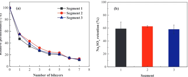
In order to check the homogeneity of the coating, a longer (40 cm long) membrane module was taken and divided into three segments of 10 cm active length and the permeability and retention of segmented sections were compared. A schematic of the segmented fiber is shown in Fig. S4. The segmented module was coated dynamically under 1 bar
pressure, while applying 0.5 m s−1
cross flow through the fiber. Fig. 3(a) shows the relative pure water permeability of each segment with a 2% deviation indicating that the sections are coated evenly. This is important to consider for longer modules where pressure drop inside the fiber can limit the proper coating, but that is not the case under the
coating conditions used here. As shown inFig. 3(b) the retention of
Na2SO4in each segment was comparable and no significant deviation
was found. The dynamic coating process may therefore be applied to industrial systems and a uniform performance is expected from the entire module. 0 1 2 3 4 5 6 7 8 9 0 20 40 60 80
Static: Dip coated
Dynamic: Crossflow (0.5 m/s, 1 bar) Dynamic: Crossflow (2 m/s, 1 bar) Dynamic: Dead end (1 bar)
(a)
0 20 40 60 80 100 0 1 2 3 4 5 7 8 0 20 40 60 80(b)
N a2 S O4 r et en ti on ( %)Coating conditions: 0.5 m.s-1, 1 bar
Fig. 2. Comparison of different modes of coating on membrane performance; (a) Relative permeability change with increasing bilayers coated under different coating techniques; (b) Effect of coating steps on membrane performance in terms of Na2SO4rejection. All experiments repeated in triplicate.
0 20 40 60 80
(a)
Segment 1 Segment 2 Segment 3 0 1 2 3 4 5 6 7 8 0 20 40 60 80 100 0 2 4 6 8 10 1 2 3 0 20 40 60 80(b)
N a2 S O4 r e te n ti o n ( % )Fig. 3. Homogeneity test of dynamic coating (a) Relative permeability of each 10 cm segments; (b) Na2SO4retention of each 10 cm segment, measured membrane coated with 7 bilayers (coating is performed with 0.1 g l−1PE containing 50 mM salt at pH 6, under 1 bar pressure and 0.5 m s−1
3.1.3. Membrane performance as NF
To check if the created membranes were indeed within the NF
performance regime, the retention of different salts (NaCl, Na2SO4and
MgSO4) and small organic molecules (Bezafibrate and Naproxen) was
investigated. Membranes coated with 7 bilayers of PAH/PAA
termi-nating with the PAA (−) layer with 0.5 m s−1cross flow and 1 bar
pressure were used for NF performance test. As can be seen fromFig. 4,
the prepared membranes are capable of rejecting Na2SO4(60%) and
organic solutes (55–70%), while monovalent ions (NaCl) and divalent
cations (MgSO4) are hardly rejected. This ion rejection is fully
con-sistent with the results of a negatively charged nanofiltration
mem-brane, that separates on the basis of Donnan exclusion. Here SO42−is
much more strongly rejected than Cl−, explaining the high Na
2SO4
rejection compared to NaCl. On the other hand MgSO4 is much less
rejected compared to Na2SO4, as the divalent cation Mg2+tends to
accumulate in the negative membrane, drawing its counter ion along. Still the high retentions of Bezafibrate and Naproxen must have to do with their size, as they have just a single charge. Based upon the results it is expected that mainly size and charge exclusion are dominating the rejection mechanism, although other factors such as affinity between membrane, solute and solvent can also play role in separation me-chanism.
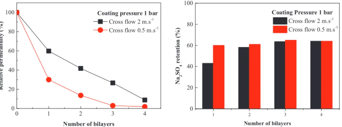
3.1.4. Upscaling of cross flow dynamic coating approach
After optimizing the dynamic coating conditions on a single fiber module, we checked the upscaling potential of this dynamic coating approach to coat modules with an effective length of approximately
200 mm housing 15 fibers in one module yielding a total effective area
of 67 cm2. Coating was performed at constant pressure of 1 bar under
two cross flow speeds (0.5 and 2 m s−1
). As shown inFig. 5with every
coating step a drop in permeability was observed and similar to single fiber module coating the drop is higher for modules coated at low cross flow speed due to accumulation of material. In contrast, the salt re-jection stays relatively constant with an increasing number of bi-layers. It seems that already after 1–2 bi-layers, the PEM coating fully covers the support membrane, after which an increase in the number of layers
does not lead to improved separation[32]. The results obtained on our
larger module scale, is fully consistent with the results obtained at the single fiber level. We conclude that the dynamic coating approach is equally suitable for coating on module level, and could likely even be used to coat existing UF modules in various industrial applications. 3.2. Fouling and cleaning studies
In the second part of this study we test the fouling propensity of PAH/PAA multilayer system and their potential as sacrificial layers for easy membrane cleaning. Fouling and cleaning studies were performed first on model surfaces (silicon wafer) in order to optimise adsorption and release conditions, and were later replicated on LbL coated mem-branes.
3.2.1. Reflectometry
Adsorption, fouling and sacrificial cleaning of PEMs was monitored on silicon wafers using optical fixed angle reflectometry. The adsorp-tion measurements on silicon wafers were started by exposing the
surface to a PE solution of PAH (0.1 g l−1, pH 6, 50 mM NaNO
3), then
switching to a PAA (0.1 g l−1, pH 6, 50 mM NaNO
3) solution. Between
subsequent adsorption steps, the substrate was rinsed with the
back-ground electrolyte solution (50 mM NaNO3) to remove excess PE and
avoid the formation of bulk complexes. Continuous switching between cationic and anionic PEs leads to a stepwise growth of the multilayers. Subsequently, a foulant solution was applied on top of differently ter-minated multilayers (PAH or PAA as the final layer). To simulate fouling two model foulants were used in this study bovine serum
al-bumin (BSA, 0.1 g l−1, pH 7) and Humic acids (HA, 0.1 g l−1, pH 5.2).
Both foulants are negatively charged at the pH conditions used for this study. Similar to the spontaneous self-assembly phenomena observed in PEs, biological materials can adsorb via electrostatic interactions. Many biological foulants are negatively charged therefore negatively charged membranes generally exhibit decreased adsorption in comparison to
positively charged membranes. As can be seen inFig. 6, this
phenom-enon was clearly observed, when the foulants introduced to the PAA (−) terminated layer, the quantity of foulant adsorbed is significantly
less at approximately 1 mg m−2for BSA and HA. In contrast, for PAH
(+) terminated layers the introduction of the foulant leads to a large
0
Fig. 4. NF membrane performance in terms of retention of mono and divalent salts and organic molecules. The tested membranes were coated with 7 bilayers of PAH/PAA at speed of 0.5 m s−1 and 1 bar pressure. Permeability of tested membrane was 6.52 ± 0.5 l m−2h−1bar−1. All experiments repeated in triplicate.
0 1 2 3 4 0 20 40 60 80 100 Cross flow 2 m.s-1 Cross flow 0.5 m.s-1
Coating pressure 1 bar
1 2 3 4 0 20 40 60 80 N a2 S O4 r e te n ti o n ( % ) Cross flow 2 m.s-1 Cross flow 0.5 m.s-1
Coating Pressure 1 bar
increase in the quantity of material adsorbed. The factor to which the mass increased for BSA and HA was 5 and 2 respectively. Results of HA fouling of PAH and PAA terminated multilayers are given in Fig. S5. Although both foulants adsorbed onto the positive (PAH) layer, they adsorbed to different degrees with BSA being adsorbed more. While this behaviour is significant, for this particular study, the foulant-polyelec-trolyte electrostatic interaction is not the primary focus here. The overall decrease in fouling propensity observed with PAA (−) termi-nated layers demonstrates that by careful selection of the final layer of a PEM, a low fouling layer can be achieved. But apart from low fouling surfaces, these multilayers can also be used as sacrificial layers to allow for easy cleaning. When a trigger solution was applied on the fouled PEMs, the adsorbed multilayers and the fouling agents are washed away
from the silicon wafer (Fig. 6), again indicating their potential as
sa-crificial coatings. When the pH is low, PAA becomes considerably un-charged and an increase in the ionic strength, then further weakens the ionic interactions resulting in disintegration of multilayers, and re-moval of all attached foulants.
3.2.2. Membrane fouling and cleaning
In this section, we demonstrate that the promising properties of multilayers as observed via reflectometry can also be applied to a membrane system. The interactions between the foulants and the membranes are investigated through cross flow permeation tests using two model foulants (BSA and HA). Fouling experiments were conducted
under very low cross flow speed (0.5 m s−1) for about 2 h with 1 g l−1
foulant. Initially the pure water permeability of the Virgin UF support was tested. The fouling propensity was measured as the ratio of the permeability at a point in time to the initial permeability. The UF support used contains negative charge and is well developed for re-tention of silica particles. Hence, the membrane is expected to already have a very low fouling propensity. Additionally, the membrane is known to be hydrophilic such that repulsive hydration forces are ex-pected to repel the hydrophobic foulants. When exposed to the foulants, the support membranes showed an average 8% decline in permeability (Fig. 7). This decline in flux is primarily due to the deposition of the foulants on the membrane surface by adsorption and aggregation. When coated membranes (with 5 and 5.5 bilayers of PAH/PAA) were exposed to foulants, it can be observed that BSA exhibited a greater
affinity for the membrane surface than HA (Fig. 7a & b), which is in line
with the results of reflectometry (Fig. 6, S5). Here we can also see the
impact of differently terminated layers (PAA and PAH) on foulant ad-sorption. A rapid flux decline was observed for PAH terminated
mem-brane during crossflow filtration of 1 g l−1BSA (pH 7). This behaviour
may indeed be explained by the electrostatic interaction between ne-gatively charged BSA molecules and positively charged PAH brane. The carboxylic functional groups of the PAA terminated mem-branes are negative and thus a strong electrostatic repulsion is expected between the negatively charged BSA molecules and the negative membrane surface. While the strong electrostatic repulsion is the most 0 1500 3000 4500 6000 7500 9000 10500 0 5 10 15 20 25 30 35 40 45 (a) + + + - -+ BSA
Fouling of PAA terminated layers
0 1500 3000 4500 6000 7500 9000 0 5 10 15 20 25 30 35 40 45 (b) Residual mass Trigger A d so rb a n ce ( m g .m -2 ) BSA
Fouling of PAH terminated layers
+ - +
-+
-+
Fig. 6. Effect of terminal layer on BSA and HA adsorption and sacrificial layer effect (a) BSA fouling of multilayers terminated with PAA (−) layer; (b) BSA fouling of PAH (+) terminated layers and effect of trigger solution (pH 3, 3 M) on desorption of fouled multilayers. Concentration of BSA 0.1 g l−1, pH 7. Rinsing solution used after every adsorption step is 50 mM NaNO3, pH 6.
Fig. 7. Permeability versus time of un-coated and coated membranes with PAH/PAA with + and − terminal layers membranes during the filtration of BSA and HA. Fouling experiments were conducted at 25 °C and 1 bar operating pressure. All experiments performed in triplicate.
important reason for improved fouling prevention, the ionised car-boxylic groups present on the membrane surface also interact with water molecules through Van der Waals forces and hydrogen bonds thereby preventing the deposition of the protein. The overall decrease in fouling of PAA terminated layers relative to PAH terminated layers and the uncoated membrane clearly highlights a viable approach of surface modification while retaining a very low fouling propensity. Antifouling results of PAA terminated layer are comparable to a UF membrane support optimised for fouling control.
3.2.3. Sacrificial membrane cleaning
In this section, we investigate the use of dynamically coated PEMs as sacrificial layers. The approach will be used for cleaning of fouled multilayered NF membranes along with the possibility of regeneration of the PEM membrane. Initially, the use of dynamically assembled PEMs as sacrificial layers was evaluated without fouling. For this 5 bilayers of PAH/PAA on a UF support were first rinsed with the trigger solution (pH 3, 3 M) in cross-flow mode at 2 bar and subsequently back-flushed with the trigger solution at 2 bar for an hour. It can be seen (Fig. 8) that the coating is fully removable with the applied trigger solution bringing the membrane resistance back to the level of uncoated
membrane support (HFS).
Subsequently the potential of this sacrificial coating approach to remove BSA foulant from the membrane is investigated. For sacrificial cleaning experiments we chose PAH terminated membrane (coated with 5.5 bilayers of PAH/PAA) fouled with BSA because this membrane
and foulant showed the highest fouling propensity (Fig. 7a). InFig. 9
we show the membrane resistance against pure water permeation for
several stages, dynamic coating (coating at 0.5 m s−1cross flow and
1 bar pressure), fouling with BSA, sacrificial cleaning and subsequent re-generation. Here the same cleaning protocol was applied for PEM removal as used for unfouled membrane, at similar conditions and number of bilayers as the unfouled membrane, the resistance of fouled membrane after cleaning went back close to the resistance of coated membrane suggesting the trigger does not effectively remove the PEM layer. This proposes that the nature of the foulant can impact the suc-cess of the layer removal. Unlike the hard spherical nature of silica
particles[34], it is believed that the BSA molecules form a thick gel
layer on the membrane surface that holds the layer in place. Conse-quently, after the cleaning step, the membrane is effectively unchanged and did not return to its pristine state as expected.
In light of these results, the order of cleaning was adjusted to in-clude backflushing as a first step followed by rinsing, so that the polyelectrolyte on the surface can be lifted off and re-suspended in a tangential flow. This approach proved to be much more effective than the previous combination as it resulted in an 86% reduction in the re-sistance (Fig. S6). Rinsing, therefore had no capacity to remove the BSA molecules while backflushing did. This is believed to be due to the fact that the trigger solution now had direct contact with the PEMs through the membrane’s structure resulting in immediate removal of the layers and the attached foulants. Complete recovery of the pristine membrane resistance was obtained when modules were backwashed at a bit higher pressure of 4 bar followed by rinsing for an hour. Following up with rinsing resulted in further removal of loosely bound material. The used commercial support can bear upto 5 bar backwash pressure and a pH as low as 1 so we do not expect any change in the membrane performance after cleaning procedure. This same support was already used by de
Grooth et al. [31] successfully in combination with sodium
hypo-chlorite and a backwash pressure of 5 bar without any reported damage to membrane. Two successive sets of BSA fouling, cleaning and re-generation experiments were performed on the same module to assess the longevity of this regeneration process. The pure water permeability and resistance were measured again and compared with the initial
values. As shown inFig. 9, the membrane maintained a relatively low
Fig. 8. Measured membrane resistance to pure water permeation at different stages of coating and sacrificial cleaning of multilayers. The sequence followed is dynamically coating the HFS membrane with 5.5 bilayers of PAH/PAA, rinsing of multilayers from inside to out for 1 h with trigger solution (pH 3, 3 M), backwashing with trigger solution from out to inside of membrane under pressure of 2 bar for 1 h and recoating of clean membrane with 5.5 bilayers of PAH/PAA. All experiments performed in duplicate.
Fig. 9. Measured membrane resistance to pure water permeation at different stages of coating, fouling and sacrificial cleaning of fouled multilayers. The sequence followed is dynamically coating the HFS membrane with 5.5 bilayers of PAH/PAA, fouling with 1 g l−1BSA, backwashing with trigger solution from out to inside of membrane under pressure of 4 bar for 8 h rinsing of multilayers from inside to out for 1 h with trigger solution (pH 3, 3 M), and recoating of clean membrane with 5.5 bilayers of PAH/PAA. All experiments performed in duplicate.
resistance after a series of runs. After the first regeneration cycle, the resistance returned close to pristine membrane resistance. The second cycle resulted in a further 20% decrease in the membrane support permeability. It can therefore be concluded that the membranes are less prone to fouling if terminated with PAA layer and can be regenerated multiple times with the applied cleaning agent and cleaning protocol. However, the cleaning is not complete after more than 1 cycle, and or continuous regeneration some additional cleaning approaches need to be taken into account.
4. Conclusions
In this study sacrificial PEMs based hollow fiber NF membranes were prepared using dynamic LbL coating under constant pressure and in cross flow mode. The effect of different cross flow speeds, pressures and mode of coating was investigated extensively and compared with dip coating method. It is shown that dynamic deposition is a simple way to modify the surface (inside) of existing hollow fiber UF support to make versatile NF membranes with low fouling propensity (if termi-nated with PAA) and which are relatively easy to clean by sacrificial layer approach. Still, even with the sacrificial layer approach, the foulant removal after 2 cycles is not complete. This indicates that the sacrificial layer approach is beneficial, but should still be combined with other cleaning approaches. Rejection performance of solutes (salts and organic micro-pollutants) by dynamically coated membranes fall in typical NF performance range (50–70% retention). Moreover this coating method with its reproducibility and homogeneity features also shon to have upscaling potential to coat existing UF membrane mod-ules.
Acknowledgments
Shazia Ilyas acknowledges the European Commission - Education, Audiovisual and Culture Executive Agency (EACEA), for her PhD scholarship under the program: Erasmus Mundus Doctorate in Membrane Engineering − EUDIME (FPA N° 2011-0014, Edition III, http://eudime.unical.it/). We would also like to thank Pentair X-Flow, The Netherlands, for providing the support membranes for this re-search.
Appendix A. Supplementary data
Supplementary data associated with this article can be found, in the
online version, athttp://dx.doi.org/10.1016/j.colsurfa.2017.09.003.
References
[1] A.W. Mohammad, Y.H. Teow, W.L. Ang, Y.T. Chung, D.L. Oatley-Radcliffe, N. Hilal, Nanofiltration membranes review: recent advances and future prospects, Desalination 356 (2015) 226–254.
[2] M. Pontié, J. Dach, M. Leparc, A. Lhassani, European Desalination Society and Center for Research and Technology Hellas (CERTH), Sani Resort 22–25 April 2007, Halkidiki, Greece, Novel approach combining physico-chemical characterizations and mass transfer modelling of nanofiltration and low pressure reverse osmosis membranes for brackish water desalination intensification, Desalination 221 (2008) 174–191.
[3] Membrane filtration technologies tackle water reuse and purification, Membr. Technol. 2007 (2007) 9–11.
[4] W. Guo, H.-H. Ngo, J. Li, A mini-review on membrane fouling, Bioresour. Technol. 122 (2012) 27–34.
[5] A. Al-Amoudi, R.W. Lovitt, Fouling strategies and the cleaning system of NF membranes and factors affecting cleaning efficiency, J. Membr. Sci. 303 (2007) 4–28.
[6] A. Al-Amoudi, P. Williams, S. Mandale, R.W. Lovitt, Cleaning results of new and fouled nanofiltration membrane characterized by zeta potential and permeability, Sep. Purif. Technol. 54 (2007) 234–240.
[7] P. Ahmadiannamini, M.L. Bruening, V.V. Tarabara, Sacrificial polyelectrolyte multilayer coatings as an approach to membrane fouling control: disassembly and regeneration mechanisms, J. Membr. Sci. (2015).
[8] G. Pearce, Introduction to membranes: fouling control, Filtr. Sep. 44 (2007) 30–32. [9] A.I. Schäfer, A.G. Fane, T.D. Waite, Nanofiltration: Principles and Applications,
Elsevier, 2005.
[10]L. Liu, D.Y.W. Di, H. Park, M. Son, H.-G. Hur, H. Choi, Improved antifouling per-formance of polyethersulfone (PES) membrane via surface modification by CNTs bound polyelectrolyte multilayers, RSC Adv. 5 (2015) 7340–7348.
[11]H. Guo, Y. Ma, P. Sun, S. Cui, Z. Qin, Y. Liang, Self-cleaning and antifouling na-nofiltration membranes-superhydrophilic multilayered polyelectrolyte/CSH com-posite films towards rejection of dyes, RSC Adv. 5 (2015) 63429–63438. [12]T. Ishigami, K. Amano, A. Fujii, Y. Ohmukai, E. Kamio, T. Maruyama,
H. Matsuyama, Fouling reduction of reverse osmosis membrane by surface mod-ification via layer-by-layer assembly, Sep. Purif. Technol. 99 (2012) 1–7. [13]D. Rana, T. Matsuura, Surface modifications for antifouling membranes, Chem. Rev.
110 (2010) 2448–2471.
[14]C. Ba, J. Economy, Preparation and characterization of a neutrally charged anti-fouling nanofiltration membrane by coating a layer of sulfonated poly(ether ether ketone) on a positively charged nanofiltration membrane, J. Membr. Sci. 362 (2010) 192–201.
[15]Y.-L. Ji, Q.-F. An, Q. Zhao, W.-D. Sun, K.-R. Lee, H.-L. Chen, C.-J. Gao, Novel composite nanofiltration membranes containing zwitterions with high permeate flux and improved anti-fouling performance, J. Membr. Sci. 390–391 (2012) 243–253.
[16]T. Kruk, K. Szczepanowicz, D. Kregiel, L. Szyk-Warszyńska, P. Warszyński, Nanostructured multilayer polyelectrolyte films with silver nanoparticles as anti-bacterial coatings, Colloids Surf. B: Biointerfaces 137 (2016) 158–166. [17]L. Setiawan, R. Wang, K. Li, A.G. Fane, Fabrication and characterization of forward
osmosis hollow fiber membranes with antifouling NF-like selective layer, J. Membr. Sci. 394–395 (2012) 80–88.
[18]L. Tang, W. Gu, P. Yi, J.L. Bitter, J.Y. Hong, D.H. Fairbrother, K.L. Chen, Bacterial anti-adhesive properties of polysulfone membranes modified with polyelectrolyte multilayers, J. Membr. Sci. 446 (2013) 201–211.
[19]L.Y. Ng, A.W. Mohammad, C.Y. Ng, A review on nanofiltration membrane fabri-cation and modififabri-cation using polyelectrolytes: effective ways to develop membrane selective barriers and rejection capability, Adv. Colloid Interface Sci. 197–198 (2013) 85–107.
[20]R. Malaisamy, M.L. Bruening, High-Flux nanofiltration membranes prepared by adsorption of multilayer polyelectrolyte membranes on polymeric supports, Langmuir: ACS J. Surf. Colloids 21 (2005) 10587–10592.
[21]M.D. Miller, M.L. Bruening, Controlling the nanofiltration properties of multilayer polyelectrolyte membranes through variation of film composition, Langmuir: ACS J. Surf. Colloids 20 (2004) 11545–11551.
[22]L. Ouyang, R. Malaisamy, M.L. Bruening, Multilayer polyelectrolyte films as na-nofiltration membranes for separating monovalent and divalent cations, J. Membr. Sci. 310 (2008) 76–84.
[23]W. Shan, P. Bacchin, P. Aimar, M.L. Bruening, V.V. Tarabara, Polyelectrolyte multilayer films as backflushable nanofiltration membranes with tunable hydro-philicity and surface charge, J. Membr. Sci. 349 (2010) 268–278.
[24]B.W. Stanton, J.J. Harris, M.D. Miller, M.L. Bruening, Ultrathin, multilayered polyelectrolyte films as nanofiltration membranes, Langmuir: ACS J. Surf. Colloids 19 (2003) 7038–7042.
[25]S.U. Hong, M.D. Miller, M.L. Bruening, Removal of dyes, sugars, and amino acids from NaCl solutions using multilayer polyelectrolyte nanofiltration membranes, Ind. Eng. Chem. Res. 45 (2006) 6284–6288.
[26]W. Jin, A. Toutianoush, B. Tieke, Use of polyelectrolyte layer-by-layer assemblies as nanofiltration and reverse osmosis membranes, Langmuir: ACS J. Surf. Colloids 19 (2003) 2550–2553.
[27]L. Krasemann, B. Tieke, Selective ion transport across self-assembled alternating multilayers of cationic and anionic polyelectrolytes, Langmuir: ACS J. Surf. Colloids 16 (1999) 287–290.
[28]N. Peng, N. Widjojo, P. Sukitpaneenit, M.M. Teoh, G.G. Lipscomb, T.-S. Chung, J.-Y. Lai, Evolution of polymeric hollow fibers as sustainable technologies: past, pre-sent, and future, Prog. Polym. Sci. 37 (2012) 1401–1424.
[29]C.Y. Feng, K.C. Khulbe, T. Matsuura, A.F. Ismail, Recent progresses in polymeric hollow fiber membrane preparation, characterization and applications, Sep. Purif. Technol. 111 (2013) 43–71.
[30]J. de Grooth, M. Dong, W.M. de Vos, K. Nijmeijer, Building polyzwitterion-based multilayers for responsive membranes, Langmuir: ACS J. Surf. Colloids 30 (2014) 5152–5161.
[31]J. de Grooth, B. Haakmeester, C. Wever, J. Potreck, W.M. de Vos, K. Nijmeijer, Long term physical and chemical stability of polyelectrolyte multilayer membranes, J. Membr. Sci. 489 (2015) 153–159.
[32]J. de Grooth, R. Oborný, J. Potreck, K. Nijmeijer, W.M. de Vos, The role of ionic strength and odd?even effects on the properties of polyelectrolyte multilayer na-nofiltration membranes, J. Membr. Sci. 475 (2015) 311–319.
[33]J. de Grooth, D.M. Reurink, J. Ploegmakers, W.M. de Vos, K. Nijmeijer, Charged micropollutant removal with hollow fiber nanofiltration membranes based on polycation/polyzwitterion/polyanion multilayers, ACS Appl. Mater. Interfaces 6 (2014) 17009–17017.
[34]S. Ilyas, J. de Grooth, K. Nijmeijer, W.M. de Vos, Multifunctional polyelectrolyte multilayers as nanofiltration membranes and as sacrificial layers for easy membrane cleaning, J. Colloid Interface Sci. 446 (2015) 386–393.
[35]B. Su, T. Wang, Z. Wang, X. Gao, C. Gao, Preparation and performance of dynamic layer-by-layer PDADMAC/PSS nanofiltration membrane, J. Membr. Sci. 423–424 (2012) 324–331.
[36]L. Ouyang, D.M. Dotzauer, S.R. Hogg, J. Macanás, J.-F. Lahitte, M.L. Bruening, Catalytic hollowfiber membranes prepared using layer-by-layer adsorption of polyelectrolytes and metal nanoparticles, Catal. Today 156 (2010) 100–106. [37]C. Liu, L. Shi, R. Wang, Enhanced hollow fiber membrane performance via
semi-dynamic layer-by-layer polyelectrolyte inner surface deposition for nanofiltration and forward osmosis applications, React. Funct. Polym. 86 (2015) 154–160. [38] C. Liu, W. Fang, S. Chou, L. Shi, A.G. Fane, R. Wang, Fabrication of layer-by-layer
assembled FO hollowfiber membranes and their performances using low con-centration draw solutions, Desalination 308 (2013) 147–153.
[39] G. Zhang, X. Song, S. Ji, N. Wang, Z. Liu, Self-assembly of inner skin hollow fiber polyelectrolyte multilayer membranes by a dynamic negative pressure layer-by-layer technique, J. Membr. Sci. 325 (2008) 109–116.
[40] D. Menne, J. Kamp, J. Erik Wong, M. Wessling, Precise tuning of salt retention of backwashable polyelectrolyte multilayer hollow fiber nanofiltration membranes, J. Membr. Sci. 499 (2016) 396–405.
[41] W.M. de Vos, A. de Keizer, M.A.C. Stuart, J.M. Kleijn, Thin polymer films as sa-crificial layers for easier cleaning, Coll. Surf. A 358 (2010) 6–12.
[42]S.A. Sukhishvili, S. Granick, Layered, erasable polymer multilayers formed by hy-drogen-bonded sequential self-assembly, Macromolecules 35 (2001) 301–310. [43]R.V. Klitzing, Internal structure of polyelectrolyte multilayer assemblies, Phys.
Chem. Chem. Phys. 8 (2006) 5012–5033.
[44]S.T. Dubas, J.B. Schlenoff, Polyelectrolyte multilayers containing a weak Polyacid: construction and deconstruction, Macromolecules 34 (2001) 3736–3740. [45]D. Kovacevic, S. van der Burgh, A. de Keizer, M.A. Cohen Stuart, Kinetics of
for-mation and dissolution of weak polyelectrolyte multilayers: role of salt and free polyions, Langmuir: ACS J. Surf. Colloids 18 (2002) 5607–5612.
[46]J.C. Dijt, M.A.C. Stuart, G.J. Fleer, Reflectometry as a tool for adsorption studies, Adv. Colloid Interface Sci. 50 (1994) 79–101.
[47]J.C. Dijt, M.A.C. Stuart, J.E. Hofman, G.J. Fleer, Kinetics of polymer adsorption in stagnation point flow, Colloids Surf. 51 (1990) 141–158.