HAL Id: hal-03128107
https://hal.archives-ouvertes.fr/hal-03128107
Submitted on 2 Feb 2021
HAL is a multi-disciplinary open access
archive for the deposit and dissemination of
sci-entific research documents, whether they are
pub-lished or not. The documents may come from
teaching and research institutions in France or
abroad, or from public or private research centers.
L’archive ouverte pluridisciplinaire HAL, est
destinée au dépôt et à la diffusion de documents
scientifiques de niveau recherche, publiés ou non,
émanant des établissements d’enseignement et de
recherche français ou étrangers, des laboratoires
publics ou privés.
FIB manufactured microstructures with low Coefficients
of Thermal Expansion
Eva Héripré, Marwen Mehrez, Andrei Constantinescu
To cite this version:
Eva Héripré, Marwen Mehrez, Andrei Constantinescu.
FIB manufactured microstructures with
low Coefficients of Thermal Expansion.
Mechanics Research Communications, Elsevier, 2021,
FIB manufactured microstructures with low Coe
fficients of Thermal Expansion
Eva Héripréa, Marwen Mehrezb, Andrei Constantinescub
aMSSMat, CNRS-Université Paris-Saclay,CentraleSupelec France bLMS, CNRS-Ecole Polytechnique, Institut Polytechnique de Paris, France
Keywords: FIB, coefficient of thermal expansion, metamaterial
1. Introduction
Natural solid materials expand when heated, as the interatomic distance increases with heat. The phenom-ena is transmitted across scales, both for cristalline or amorphous materials. The development of modern de-vices working in multi-physics environments, combin-ing at least mechanical and thermal loadcombin-ings, such as thermal engines, biomedical structures, semiconductor wafers, optical, nuclear or solar energy structures re-quire that the employed materials have a high stability under the service loading. Uncontrolled thermal expan-sion between different parts of a structure can lead to high incompatible strain, localized plastic strain and fi-nally failure and has been a subject of concern in fatigue design. Dilatation incompatibilities are at the origin of residual stresses and the consequent fatigue failure of the structures, see examples in Ref. [1] or [2] for struc-tures in industry Ref. [3] for geological strucstruc-tures in nature.
Designing materials and structures with specified co-efficients of thermal expansion (CTE) and particularly with low or negative CTE is of peculiar interest. Mate-rials with low CTE can be obtained by either (a) tun-ing an appropriate material, for example by manipu-lating the chemical composition (see Ref. [4]), intro-ducing in-situ secondary phases into a matrix Ref. [5], etc. or by (b) employing a micro-architectured mate-rial structure. The concepts of microstructured materi-als with low CTE have already been sketched in Ref. [6] and obtained by mathematical shape optimization in Ref. [7] and later manufactured at the macroscopic scale [8, 9, 10]. At the microscopic scale thin films with low CTE were microfabricated from titanium and alu-minum films in Ref. [11]. Most of these examples are planar, i.e. 2D structures as discussed on a series of lat-tice examples in Ref. [12]. However recently 3D pro-posals have emerged, like the origami type structures Ref. [13], the bimaterial lattice structures discussed in
Ref. [14], or the lattice structure obtained from printed polymer structures reported (see Ref. Qu:2016hg). Let us further remark that more generally the control of the CTE permits to design foldable structures, denoted also as 4D printing, as shown in Ref. [15].
The objective of this work is to demonstrate that structures with low CTE’s can also be manufactured at the micrometric scale using tradintional milling and welding using a focused ion beam (FIB). In order to reach this target, we started from previous theoretical work reported in [8] and experimental work at the large scale, e.g. Ref. [10] where a bi-material structure was proposed, tested and scaled down an similar shape at the microscopic scale. In this paper, starting from two micrometric sheets of steel and aluminum, we milled the basic elements of the unit cell and welded final unit cell of the architectured microstructure. The heat expansion coefficient was determined using digital im-age correlation during the heating up of the microstruc-ture on a heating element in a scanning electron mi-croscopy (SEM). It is reported that specimen exhibits a thermal expansion coefficient significantly lower than either of the constituent materials. Moreover the real-ized structure is an example of structures which can be constructed using the facilities of the Focused ion beam (FIB).
The paper is organized as follows. The next section presents the design of the sample and discusses briefly several unit-cell proposed in the literature. It contin-ues with the description of the materials and the manu-facturing of the sample. In Section 3 are presented the heating experiments and the measurements of the ther-mal expansion coefficient while in Section 4-5 are dis-cussed these results. A summary of main findings are given in Section 6.
2. Sample: design and manufacturing
The design discussed next draws its inspiration from
Ref. [8]. This work showed that two- or
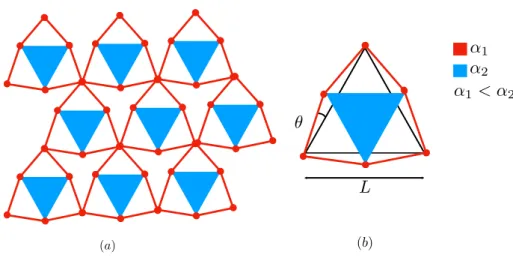
three-dimensional lattices trusses can exhibit a global homog-enized CTE global smaller than the ones of its compo-nents. The simplest pattern can be designed using a unit cell combining a triangle and a hexagonal shape with CTE’s α1and α2respectively. The complete lattice will
exhibit a small CTE if the condition α1 < α2 is
sat-isfied. Next we shall replace the inner triangle trusses with a triangular plate, see Figure 6. The underlying mechanism creating the small CTE is triggered by a larger thermal expansion of the inner triangle which im-poses an inward rotation of the outer trusses and induces an overall contraction of the non-connected vertices of the hexagon. The periodic reproduction of the unit cell (UC) creates a structure with vanishing CTE.
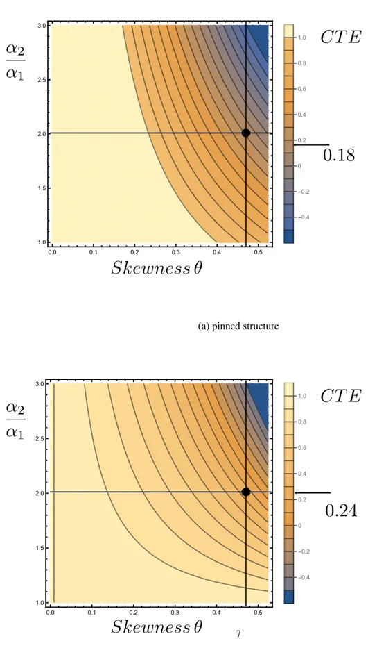
Moreover, Ref. [16] provided the analytic expres-sion for the global homogenized CTE, α in terms of the material and structural value of the constituents. For pinned lattice structure, we have:
α α1 = 1 −1 2 α2 α1 ! (sin 2 θ) √1 3+ tan θ ! 1 −1 2(sin 2 θ) 1 √ 3+ tan θ ! (1)
where θ is the skewness, an angle characterizing the ge-ometric construction and α1, α2 denote the CTE of the
trusses and polygons respectively. For a bonded struc-ture, we have: α α1 = 1 − (C1tan θ − 12 √ 3)(cos θ+ √ 3 sin θ)(α2 α1 − 1)× (C1( √ 3 cos θ − sin θ)+ 12( √ 3+ 2E1A1 E2A2 )(cos θ+ √ 3 sin θ))−1 (2)
where C1 is a relative bending stiffness and Ei, Ai, i =
1, 2 are the Young modulus and the area of the trusses of the materials. The design possibilities in terms of at-tainable CTE’s are represented in Figure 6 and show that values of negative or vanishing CTE’s can be obtained with these structures.
This design procedure was successfully manufac-tured and tested in [16] on lattice structures with angle θ ≈ 30◦ titanium trusses (α
1 = 8.6 ppm/◦C) and
alu-minum (α2 = 23.1 ppm/◦C) plates (resulting in a unit
cell with α ≈ 2.56ppm/◦C) with a unit cell diameter of
12.4 mm. The complete lattice structure had a CTE of 2.56 ppm/◦C.
The design proposed here is a scaling down of the basic unit cell to a diameter diameter of ≈ 160 µm and its manufacturing from thin sheets: a steel sheet for
outer truss with CTE α1 = 12 ppm/◦C and thickness
of 25 µ m and an aluminum sheet for the inner triangle with CTE α2= 24.3 ppm/◦Cand a thickness of 15 µ m.
The skewness angle θ was equal to 26.8◦. The
esti-mated CTE’s for both pinned and bonded lattices struc-tures are represented by dot symbols on Figure 6 and
attain theoretically homogenized CTE of 4.45ppm/◦C
and 5.97ppm/◦Crespectively.
In order to achieve the small size we shall use a man-ufacturing procedure under SEM-FIB consisted in the next steps:
(i) milling of the outer steel hexagon truss and the inner aluminum triangle. The hexagon is linked to the external support on two points to minimize bending of the final unit cell.
(ii) extraction of the inner triangle with the tungsten needle of the micromanipulator.
(iii) inlay of the inner triangle in the outer hexagon (iv) welding of the corners of the triangle with the
hexagon using a Platinum ion-induced deposition. (v) deposition of the measurement grid by
electron-beam lithography.
The manufacturing was performed on a Helios-660 ap-paratus combing scanning electron microscopy (SEM) observation and a Focused ion beam (FIB) high preci-sion milling. FIB high voltage has been set to 30kV and the highest beam current (65nA) is chosen in order to minimize manufacturing time. The hexagon truss was milled in 2 hours and 45 minutes and the aluminum tri-angle in 45 minutes. Manipulation of the components is performed by an easylift micromanipulator and a Pt gaz injection to link components to the needle. Additionally, for the deformation tracking using digital image correla-tion, a gold grid has been deposted on a ThermoFisher QUANTA 600 FEG-SEM equipped with Raith Elphy Quantum electron-beam lithography system. The mi-crogrid step is 4 µm.
The manufacturing procedure is illustrated in Figure 3. A precise observation of the elements of the units cell, shows that the milled geometry of the outer truss is geometrically different from the perfect truss. This is probably due to the higher milling time and power necessary to mill the truss. Small movements of the ion beam and of the structure itself caused to heating, ther-mal expansion and release residual stresses are another possible explanation of the difference. In contrast the milling of the aluminum triangle was better controlled and the final shape is closer to the initial design. An-other defect of the milling is the varying thickness of the hexagonal truss due to matter re-deposition on the face bottom of the truss.
3. Experimental measurements
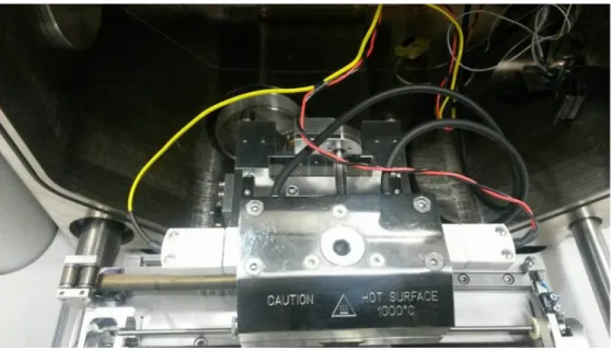
Heating experiments of the complete structure have been performed in a FEI QUANTA 600F SEM (Scan-ning Electron Microscope) apparatus equipped with a 1000◦heating stage from FEI/ThermoFisher, see fig. 4 for details. A heating path with a rate of ≈ 5◦C/min with dwell times for temperature homogenization„ see Figure 6 was imposed on the structure and images have been taken at different steps and processed using digital image correlation.
The first heating test was performed only on the alu-minum triangle in order to validate the procedure and to estimate the measurement errors.
The second heating test was on the complete structure of the unit cell comprising both the hexagonal truss and the aluminum triangle. The heating histories of both tests are displayed on Figure 6, where #1 and #2 denote the first and second test respectively.
The surface strain, ε= εi jei⊗ ej i, j = 1, 2 with
ei the unit vectors of the Cartesian coordinate system
has been obtained by using digital image correclation from pictures shot in the SEM. The digital image cor-relation was performed using CMV software [17, 18]. Images where secondary electron images shot under the following electron beam conditions : acceleration volt-age 20kV, spot size 4 under a 50 Pa low Vacuum with chamber pressure. Finally 4 frames are shot within 29 s are combined for the final image.
The mean strain within the aluminum triangle has been computed as an average over the green area in fig. 5. The procedure was chosen to avoid errors due to the grey level variation in the image at the boundaries of the traingle due to, metal re-deposition and lightning varia-tion. The mean strain of the non-connected vertices of the outer hexagon have been estimated from their dis-placements using combining measurements and compu-tations.
4. FEM modelling
A finite element model of the unit cell has been constructed with Z-set software, see www.zset-software.com. The material is considered to be linear thermo-elastic. The material coefficients are listed in Table 6. The 3D structure has been obtained by ver-tical extrusion of the upper face of the unit cell. The real shape in terms of lengths and thickness has been taken into account, (i.e. see Figure 7). The welds are considered as to be perfect and therefore the displace-ments of the steel truss and the aluminum triangle are perfectly bonded. The variation of the thickness of the
outer truss observed by SEM, see section 2, has been neglected and the thickness is considered as homoge-neous. Boundary conditions were close to the experi-ment imposed displaceexperi-ments on the hexagon holder and free surfaces. They have not been adapted for the com-putation of the effective material parameters of a peri-odic structure based on this unit cell. Figure 7 displays the initial and the deformed mesh by an amplification factor of 100. at 100◦C, illustrating the combined ex-pansion of the inner triangle and the contraction of the outer hexagon at the origin of the small CTE.
5. Results and Discussion
We shall discuss next the heat expansion experiments, test #1 and #2, on the sole aluminum triangular inlet and on the complete unit cell structure, respectively.
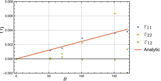
The measurement results of the heat expansion of the aluminum triangle are presented on Figure 8. One can
remark a good match between the measured ε11,
hor-izontal strain, and the theoretical strain computed for free heat expansion. The horizontal axes is the direc-tion of the electron beam scanning, which provides bet-ter accuracy when compared with other directions. Un-fortunately, complementary experiments with a rotated specimens with respect to the scanning direction of the beam have not been performed during this experimental campaign. The estimation of the relative measurement errors as obtained by DIC on two images of the same triangle at the same temperature is equal to a maximum value of 10−4.
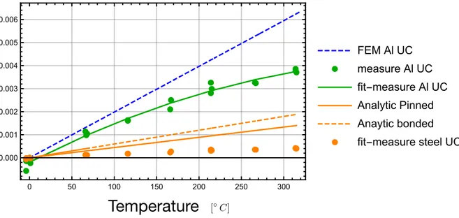
The measurement results of the heat expansion of the complete structure, i.e. bimaterial unit cell are pre-sented on Figure 9. The figure also displays results from finite elements computation of the heating experi-ment and analytic expression of CTE given in equations (1) and (2). One can remark that the stiffness of the outer steel hexagon does not inhibit the expansion of aluminum inlet by a large amount and does not
con-tribute by a stiffening mechanism to the low CTE of
the unit cell. At small temperatures the finite element computations of the heat expansion of the unit cell pro-vides an excellent match with the expansion measure-ments the aluminum inlet. This correspondance is lost with increasing temperatures, as the stiffness and the CTE of aluminum vary. It can be seen that the evolu-tion of strain with temperature is well approximated by a second order polynomial as displayed. Not surpris-ing, the outer steel hexagon exhibit an almost vanishing mean strain, when computed as a mean strain value on the triangle the non-connected vertices, as these vertices turn inward with the rotation of the outer trusses. The 3
evolution of mean strain of the hexagon with temper-ature has a smaller slope when compared to evolution of the homogenized pinned or bonded lattice structure. This can be explained by the lower stiffness acting on the non-connected vertices in a free unit cell. How-ever, unit cell’s in a pattern surface are connected ex-actly through these vertices and the global movement is more restricted in this case. Additional aspects ex-plain quantitative differences between the experimental results and the models: the geometrical differences in the real structure and the finite element model, as its for example the case the thickness, the temperature varying material coefficients, the effect of the welds which have been assumed as a perfect bonding, the temperature dis-tribution in the structure assumed to be homogeneous, which is not necessary the case as its heated through direct contact of the unit cell with the heating stage, etc.
6. Conclusion
This work demonstrates experimentally the ability to manufacture complex thin bi-material micrometric metastructures within a FIB. From steel and aluminium with CTE’s of α1 = 12 ppm/◦Cand α2= 24.3 ppm/◦C
respectively, we were able to construct a unit cell, which exhibits a CTE of 0.1 ppm/◦Cin non-connected condi-tions. This values is significantly lower than the CTE
of the respective constituents of the structure. The
microstructure has been manufactured using a FIB by milling thin foils and welding the parts together. A fi-nite element analysis, corresponding to the real milled shape showed to be in good agreement with the ther-mal expansion experiments. The results equally assess the robustness of the design sensitivity in reaching low CTE with respect to variations the shape of the unit cell. This work is a proof of concept and opens up a com-plete procedure to manufacture thin metallic structures with a tunable properties. It opens up to new perspective to test the procedure on larger lattice structures contain-ing several elementary cells and also to combine the de-sign with other microfabrication techniques. The results can be further refined by completing the strain measure-ments with thermal measurmeasure-ments at the small scale.
Acknowledgement
This work was partially performed during the intern-ship of M.M. in the LMS.
[1] A. Constantinescu, E. Charkaluk, G. Lederer, L. Verger, A global computational fatigue design method for structures un-der thermomechanical loading: Application to cast iron exhaust manifolds, Int.Journal Fatigue 26 (2004) 805–818.
[2] Amiable, S., Chapuliot, S., Constantinescu, A., Fissolo, A., A comparison of lifetime prediction methods for a thermal fatigue experiment, Int.J.Fatigue 28(7) (2006) 692–706.
[3] L. Jeannin, L. Dormieux, T. Carlioz, Nucleation of thermal cracks at the wall of a rock mass, Mechanics Research Com-munications 97 (2019) 57–62.
[4] J. Chen, L. Hu, J. Deng, X. Xing, Negative thermal expansion in functional materials: controllable thermal expansion by chem-ical modifications, Chemchem-ical Society Reviews 44 (11) (2015) 3522–3567.
[5] J. Liu, Y. Gong, J. Wang, G. Peng, X. Miao, G. Xu, F. Xu, Re-alization of zero thermal expansion in la(fe,si)13-based system with high mechanical stability, Materials & Design 148 (2018) 71 – 77.
[6] R. Lakes, Cellular solid structures with unbounded thermal ex-pansion, Journal of Materials Science Letters 15 (6) (1996) 475– 477.
[7] O. Sigmund, S. Torquato, Design of materials with extreme thermal expansion using a three-phase topology optimization method, Journal of the Mechanics and Physics of Solids 45 (6) (1997) 1037–1067.
[8] C. A. Steeves, S. L. dos Santos e Lucato, M. He, E. Antinucci, J. W. Hutchinson, A. G. Evans, Concepts for structurally ro-bust materials that combine low thermal expansion with high stiffness, Journal of the Mechanics and Physics of Solids 55 (9) (2007) 1803 – 1822.
[9] J. Berger, C. Mercer, R. M. McMeeking, A. G. Evans, The de-sign of bonded bimaterial lattices that combine low thermal ex-pansion with high stiffness, Journal of the American Ceramic Society 94 (s1).
[10] E. Gdoutos, A. A. Shapiro, C. Daraio, Thin and Thermally Stable Periodic Metastructures, Experimental Mechanics 53 (9) (2013) 1735–1742.
[11] N. Yamamoto, E. Gdoutos, R. Toda, V. White, H. Manohara, C. Daraio, Thin Films with Ultra-low Thermal Expansion, Ad-vanced Materials 26 (19) (2014) 3076–3080.
[12] K. Wei, H. Chen, Y. Pei, D. Fang, Planar lattices with tai-lorable coefficient of thermal expansion and high stiffness based on dual-material triangle unit, Journal of the Mechanics and Physics of Solids 86 (2016) 173–191.
[13] E. Boatti, N. Vasios, K. Bertoldi, Origami metamaterials for tun-able thermal expansion, Advanced Materials.
[14] Q. Wang, J. A. Jackson, Q. Ge, J. B. Hopkins, C. M. Spadaccini, N. X. Fang, Lightweight mechanical metamaterials with tunable negative thermal expansion, Physical review letters 117 (17) (2016) 175901.
[15] S. Pandini, N. Inverardi, G. Scalet, D. Battini, F. Bignotti, S. Marconi, F. Auricchio, Shape memory response and hierar-chical motion capabilities of 4d printed auxetic structures, Me-chanics Research Communications 103 (2020) 103463. [16] C. A. Steeves, S. L. dos Santos e Lucato, M. He, E. Antinucci,
J. W. Hutchinson, A. G. Evans, Concepts for structurally ro-bust materials that combine low thermal expansion with high stiffness, Journal of the Mechanics and Physics of Solids 55 (9) (2007) 1803–1822.
[17] M. Bourcier, M. Bornert, A. Dimanov, E. Héripré, J. Raphanel, Multiscale experimental investigation of crystal plasticity and grain boundary sliding in synthetic halite using digital im-age correlation, Journal of Geophysical Research: solid earth 118 (2) (2013) 511–526.
[18] L. Wang, M. Bornert, D. Yang, E. Héripré, S. Chanchole, B. Halphen, A. Pouya, D. Caldemaison, Microstructural insight into the nonlinear swelling of argillaceous rocks, Engineering Geology 193 (2015) 435–444.
Stable Periodic Metastructures, Experimental Mechanics 53 (9) (2013) 1735–1742.
Material Young’s modulus (GPa) Poisson’s ratio CTE (◦K)1
Aluminum 70 0.3 24.3e-6
Steel 210 0.3 12.e-6
Table 1: Material coefficients used in the FE model
(a)
↵
1↵
2↵
1< ↵
2✓
L
(b)Figure 1: The bi-material structure with small coefficient of thermal expansion (CTE) consisting of rods of with CTE α1and triangular plate with
CTE α2(α1< α2) from [16] and [19]. (a) pattern of periodic distribution of unit cells (b) unit-cell. Geometric shape parameters are L the length of
0.0 0.1 0.2 0.3 0.4 0.5 1.0 1.5 2.0 2.5 3.0 -0.4 -0.2 0 0.2 0.4 0.6 0.8 1.0
CT E
↵
2
↵
1
Skewness ✓
0.18
(a) pinned structure
0.0 0.1 0.2 0.3 0.4 0.5 1.0 1.5 2.0 2.5 3.0 -0.4 -0.2 0 0.2 0.4 0.6 0.8 1.0
CT E
↵
2
↵
1
Skewness ✓
0.24
(b) bonded structureFigure 2: Contourplots of the relative homogenized CTE α/α2in terms of the geometrical characteristic θ and the contrast of the CTE of the two
materials,α2
α1, see equations (1) and (2) as well as Ref. [8].
(a) (b)
(c) (d)
(e) (f)
Figure 3: The manufacturing steps of structure: (a,b) Final shapes of the outer hexagon and inner triangle after milling (c) extraction and inlay of the triangle, (e) final structure after welding (f) final structure with the measurement grid.
Figure 4: The heating stage at the entrance of the SEM chamber with the specimen holder.
Figure 5: The measurement grid for computing the expansion of triangle during the heating test. 9
0 20 40 60 80 100 120 0 50 100 150 200 250 Test #1 Test #2 [ C]
Temperatur
e
Time [s]GIBI FECIT
(a) initial mesh
GIBI FECIT
(b) deformed mesh
Figure 7: Upper view of bimaterial unit cell: (a) initial and (b) deformed mesh by an amplification factor of 100. at 100◦C.
0 50 100 150 -0.002 0.000 0.002 0.004 0.006 0.008
Analytic
"
"
11
"
22
"
12
✓
Figure 8: Evolution of the mean measured strain of the free aluminum triangular inlet as a function of temperature and comparison with the linear evolution predicted by a CTE of α2= 23.1 ppm/◦C.
"
11
[ C] 0 50 100 150 200 250 300 0.000 0.001 0.002 0.003 0.004 0.005 0.006 FEM Al UC measure Al UC fit-measure Al UC Analytic Pinned Anaytic bonded fit-measure steel UCTemperature
Figure 9: Evolution of the mean strain of the aluminum inlet, the outer steel hexagon as a function of temperature and compared with results from finite elements and analytic expression of CTE, (1) and (2).