4th International Conference on Estuaries and Coasts 8-11 October 2012, Water Resources University, Vietnam
SIMPLIFIED ASSESSMENT OF SHIP IMPACT ON NAVIGATION
LOCK GATES
Loïc BULDGEN1), Philippe RIGO2) and Hervé LE SOURNE3) 1) ANAST, University of Liège
Chemin des Chevreuils 1, Liège, 4000, Belgium e-mail: [email protected]
2) ANAST, University of Liège
Chemin des Chevreuils 1, Liège, 4000, Belgium e-mail: [email protected]
3) LE2M, ICAM Nantes
Avenue du champ des Manoeuvres 35, Nantes, 44470, France e-mail: [email protected]
Abstract
This paper presents a simplified methodology for treating collisions of ships with lock gates. The goal is to obtain a good approximation of the law relating the resistance of the gate and the penetration of the striking vessel. To do so, we assume that the initial kinetic energy of the ship is dissipated by deforming the structure. As a first step, deformations are assumed to take place in localized regions. However, for larger indentations, a global bending mode is postulated on the entire gate. The first part of the article is devoted to a brief presentation of the basic law relating and under the hypothesis of a local deforming mode. In the second part, we shortly expose the way for dealing with the global bending mode. Finally, the last section presents a comparison between numerical results obtained by finite element analyses and those derived by our simplified methodology. A quite good accordance is found between the two approaches.
Keywords: ship collision, upper-bound theorem, super-elements, local mode, global mode.
1. INTRODUCTION
This paper presents a simplified analytical method for estimating the structural resistance of classical lock gates submitted to a collision with a given ship. The main objective of this work is to develop a simplified tool for a quick estimation of the ability of a gate to resist to an impact. By so doing, the goal is to provide engineers with an effective tool allowing them to perform a quick optimization of their structure in the pre-design stage. The idea is to propose and alternative way to classical finite element analyses, which are rather time expensive for the first phases of a project, especially when optimization is needed.
The methodology exposed here is quite innovative, as there are few papers in the literature dealing with this topic. Of course, some results are already available, especially in the domain of ship-ship collisions. For example, Simonsen (1999), Jones (1991), Wierzbicki (1995) and Wang (2002), amongst others, developed some refined analytical models for characterizing the behavior of various structural elements during an impact. These researches constitute a good basis for treating collision
against lock gates. In a similar way than Ueda (1984) or Lützen (2000), the idea developed hereafter is to decompose the gate into different large structural components called “super-elements”. This idea has already been successfully applied by Le Sourne (2004).
2. METHODOLOGY
2.1. General parameters of the study
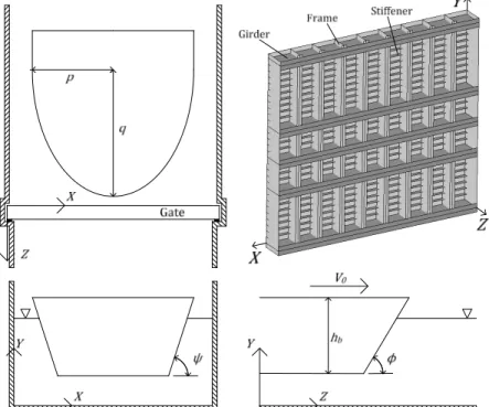
In this paper, we consider a ship having a total mass and an initial velocity . The shape of the bow is assumed to be parabolic, with given radii and . The ship sections are defined by the height ℎ , the side angle and the stem angle (see Figure 1). The gate under consideration is composed of a plating reinforced by frames (vertical stiffeners) and girders (horizontal stiffeners). Some additional smaller stiffeners are also present in the transverse direction for preventing the plating to buckle. Its total horizontal and vertical length are denoted by and . The structure is assumed to be supported by the lock walls in = 0 and = , but also in = 0, where the existence of a sill is assumed.
Fig. 1 – General overview of the collision parameters
When the gate is impacted by the vessel, it will deform in order to dissipate the collision energy. Consequently, the structure will be able to withstand a striking ship with mass and velocity if it is able to transform the total kinetic energy into internal deformation energy. Of course, deformations have to remain acceptable with respect to some prescribed criteria (failure, maximal admissible deformation, loss of stability...). For dissipating the initial collision energy, we assume that the gate may deform into two different modes:
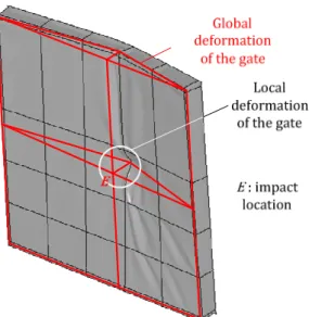
• the local one, corresponding to a localized crushing of structural elements. This mode is activated at the beginning of the collision process and implies only confined displacements (see Figure 2). • the global one, associated to an overall motion of the gate. This mode is activated for large
penetrations of the ship, which results in an entire bending of the gate (see Figure 2).
The transition between both deformation modes is assumed to occur abruptly, when the local indentation of the ship is sufficient enough to imply a switch to an overall bending process.
Fig. 2 – Global and local deforming modes 2.2. Local deforming mode
For evaluating the resistance in the local deforming mode, the gate is divided into various structural components called super-elements. They are assembled together in order to represent the skeleton of the impacted gate. During the localized indentation process, the super-elements are progressively activated as the ship is moving forwards. For the type of gate considered in the present paper, three different super-elements have been developed for estimating the local resistance:
• Super-element 1 (SE1) is a plate impacted perpendicularly to its plane, used for modeling plating components (see Figure 3a).
• Super-element 2 (SE2) is a T cross section plate submitted to an in-plane load and is used for modeling girders and frames components (Figures 3b).
• Super-element 3 (SE3) is used for modeling the impact on intersections between girders and frames (see Figure 3c).
The behavior of the material constituting each super-element is supposed to be rigid-plastic. The corresponding flow stress is denoted by . In order to completely define a super-element, it is required to know the law relating its crushing resistance and the indentation of the ship. This is achieved by applying the upper-bound theorem. Therefore, to determine the resistance of a super-element, we first have to imagine a realistic collapse mechanism. For each value of , we then evaluate the internal energy dissipated by the element during this deformation process. Finally, by application of the principle of virtual velocities, it is possible to derive the load required for ensuring the postulated collapse pattern. 23E194D953
Fig. 3 – Definition of the super-elements
As the goal of this paper is to detail a methodology for rapidly estimating the collision resistance, we will not focus on the complete mathematical procedure leading to the analytical relation between
(a) (b)
the force and the indentation . Only the fundamental hypotheses and results are therefore presented in the following part of the text. In accordance with the upper-bound theorem recalled above, the first step for developing a super-element is to imagine a deformation mechanism which is kinematically admissible. This is explained hereafter.
For super-element 1, we assume that the deformation pattern is the one represented on Figure 4a. The collided plate is submitted to an out-of-plane displacement field ( , ), which is maximal immediately under the impact point and decreases linearly until the four supported edges. During this process, plastic dissipation occurs principally because of membrane extension. The energy concerned by bending effects in plastic hinges may be neglected for large values of the penetration . According to Zhang (1999) and Lützen (2001), the law relating and is given by:
=2 3√3 ( + !)("1 + "2) $ 1 !+ 1 " "!% (1)
where is the flow stress, , !, " , "! are geometrical dimensions locating the impact point on the collided plate (see Figure 4a) and is the plating thickness.
(a)
(c)
(b)
Fig.4 – Deformation pattern for each super-element
For super-element 2, we suppose a local mode which causes the web to fold like a concertina during the impact. In other words, this element is crushed by forming a certain number of successive folds of height 2 (see Figure 4b). Consequently, for being kinematically acceptable, this deformation pattern has to concentrate confined rotations in various plastic hinges, and also membrane extension in the triangular surfaces submitted to rotation. This is illustrated on Figure 4b: in the initial configuration, three inclined plastics hinges &'( , &)( and &*( are formed. They allow the triangular surfaces &(') and &()* to rotate freely in comparison to each other. On the other side, the two horizontal hinges *) and ') allows for a relative rotation of surfaces (*' and &*' . However, the folding process may not take place by considering only rotation of rigid triangular surfaces along inclined and horizontal plastic hinges. For providing compatibility between all the rotating surfaces, it is also required to develop membrane straining in all regions. This concept is well
illustrated by Simonsen (1999) for example. As a consequence, super-element 2 dissipates energy by both bending and membrane effects. Without entering in further details, the resistance for a given penetration is: = ( + !) +, -! 4 + -! ! + - ! 2 !/ (2)
where is the flow stress, , ! are geometrical parameters defined in accordance with the impact point location (see Figure 4b) and - is the web thickness (see Figure 3b). The parameter is determined by minimizing the mean crushing force over one fold. It is found to be
= 1,3 ! -/12. These analytical formulae are quite close from the developments performed by Simonsen (1999), Hong (2008) and Zhang (1999).
For super-element 3, when the contact is established between the ship and the intersection of two perpendicular members, we make the assumption that crushing occurs in a region 4 (see Figure 4c).
In the present case, we make the hypothesis that the intersection axis between horizontal and vertical elements remains straight during crushing. This implies that the deformation pattern is symmetric on all the four wings constituting the super-element. We will therefore focus on describing the situation for only one wing (see Figure 4c). The folding mechanism is made of two triangular surfaces &') and ')5, rotating along the plastic hinges &', ') and '5. The two remaining triangles
&(' and '*5 are simply submitted to compression along the intersection axis. In order to maintain
compatibility with the remaining part of the intersected elements, we also have to admit a relative rotation along &) and )5 . Moreover, this cannot be achieved without imposing membrane deformations on the two rotating triangles &') and ')5. This problem has been extensively studied by Amdahl (1983), who proposed to use the following formula for evaluating the average resistance provided by such super-element:
=4 -√3 67 1 4 + 4!∙ arcsin $√1 + 41 !% + 4? + , -! 2 (1 + 4) (3)
where is the flow stress, 2 is the height of one fold, - is the web thickness of the intersecting members and 4 = 0.573 is a parameter calculated by Amdahl (1983).
With formulae (1) to (3), it is possible to determine the resistance in the local deforming mode. To do so, for a given indentation of the vessel, we just have to detect which super-elements are activated. This may be achieved only by geometric considerations, as we precisely know the structure of the gate and the shape of the striking vessel (see section 2.1). Then, for each activated super-element, we can now estimate the individual force acting against any further penetration of the ship. Consequently, for a given value of , if C elements are activated, the total resisting force in the local mode DEF is simply obtained by summation.
2.3. Global deforming mode
The developments exposed in the previous section leads to the determination of the local resistance DEF, which is physically the force opposed by the gate only by assuming crushing in a region located around the impacting bow. Of course, it is clear that this situation is coherent at the beginning of the collision process. But as the ship is moving forwards, this way of deformation becomes more and more energy-dissipating, so the local force DEF is increasing unrealistically. As a consequence, when it becomes too difficult for the ship to progress by local indentation, the global mode is activated. This time, we assume that further penetration of the vessel requires a generalized
motion of the gate. In fact, at a certain stage, overall bending of the gate appears to be less dissipative than local crushing. There must be therefore a switch from local to global mode.
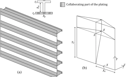
Fig. 5 – Structural model of the gate for the global deforming mode
In order to evaluate the global resistance GDE when overall bending occurs, we can imagine that the gate is only made of horizontal independent beams, submitted to a flexural motion between the two supports offered by the lock walls (see Figure 5). These beams are composed of the gross cross section of the girders, to which is added a collaborating part of the girder. The extension of this effective length ℎ (see Figure 5) is calculated according to the rules prescribed by Eurocode 3. Of course, by so doing, we totally neglect the orthotropic behavior of the gate. However, this hypothesis is not excessively conservative, as vertical frames don’t play an important role in the global bending.
The procedure for evaluating GDE is still based on the upper-bound theorem. So we first have to define a kinematically admissible displacement field H( , ) for the entire gate. In the present case, as the structure is supported in = 0, = and = 0, the displacement pattern shown on Figure 5b is kinematically admissible (note that * is the initial contact point between the ship and the gate). Each of the previously defined beams is then submitted to the postulated displacement field H( , ). For evaluating the resistance under the subsequent deformations, the following formula is used:
= *I JKK!H! ∙K + K KK!H!/ ∙ L M
= KNK + CKΔK (4) where * is the Young’s modulus, I is the inertia of the cross section depicted on Figure 5a, is the bending moment and C is the normal force. The first formula gives the elastic resistance. The second one considers a plastic behavior of the beam, involving some rotation N and axial straining Δ in plastic hinges. In this case, and C are related by an adequate interaction criteria. More details about local and global deforming modes are given by Buldgen (2012).
3. RESULTS AND DISCUSSIONS
In order to validate our simplified analytical approach, we used the non linear finite element code LS-DYNA for simulating a collision between the ship and the gate presented on Figure 1. 6955 and
(a)
92671 Belytschko-Tsai shell elements were required for modeling respectively the vessel and the
struck gate. This leads to a regular mesh size of 10 RS × 10 RS. The material constituting the gate obeys to a classical steel law, while the vessel is assumed to be perfectly rigid. More details about both structures are given in Appendices 1 and 2. The main result given by LS-DYNA is the curve showing the evolution of the resistance with respect to the indentation . This is shown on Figure 6, where we also represented our analytical results. As it can be seen, there is a quite good accordance between the two approaches. Moreover, our simplified methodology leads to quite conservative results.
Figure 6 – Numerical results provided by LS-DYNA and simplified analytical results
4. CONCLUSIONS
The results exposed in the previous section are quite promising for engineers responsible for the design of new lock gate. At the early stage of design, they don’t necessary have time to perform several finite element analyses for optimizing their structure. It is therefore important to provide them with time-effective tools.
As a consequence, the graphs exposed here above may be of importance. Indeed, for a ship with given mass and velocity , these curves give the maximal penetration U and force U to which the gate will be submitted for dissipating the kinetic energy !/2. According to various criteria related to the lock project itself, these values of U and U may not be acceptable. Consequently, engineers have to reinforce their initial structure. An iterative process is then eventually required, which can be easily conducted through our simplified methodology.
5. APPENDIX 1 – Material properties
Density V 7850 4X/SY
Poisson’s ratio Z 0.33
Yield stress 240
Young’s modulus * 210 000 Tangent modulus *[ 1018
Figure 7 – Material law for numerical simulations
0 2000 4000 6000 8000 10000 12000 14000 0 0,1 0,2 0,3 0,4 0,5 0,6 0,7 0,8 0,9 1 1,1 C ru sh in g R e si st a n ce P (k N ) Total Penetration δ (m) Analytical Results Numerical Results
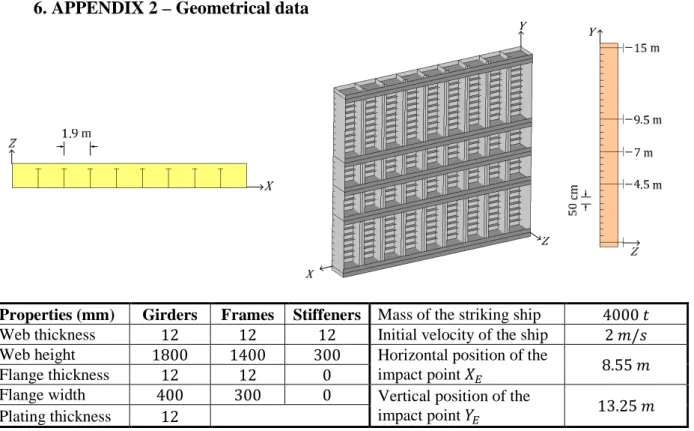
6. APPENDIX 2 – Geometrical data
Properties (mm) Girders Frames Stiffeners Mass of the striking ship 4000
Web thickness 12 12 12 Initial velocity of the ship 2 S/\
Web height 1800 1400 300 Horizontal position of the
impact point ] 8.55 S
Flange thickness 12 12 0
Flange width 400 300 0 Vertical position of the
impact point ] 13.25 S
Plating thickness 12
Figure 8 – Numerical information on the gate and on the collision scenario
7. REFERENCES
Amdahl J. (1983). Energy absorption in ship-platform Impact. PhD Thesis, Department of Marine Technology, The University of Trondheim.
Buldgen L., Le Sourne H., Rigo P. (2012). Simplified analytical method for estimating the resistance of lock gates to ship impacts. Journal of Applied Mathematics, 2012, 39p.
European Committee for Standardization (2003). Eurocode 3: Design of steel structures. CEN, Brussels, Belgium.
Hong L., Amdahl J. (2008). Crushing resistance of web girders in ship collision and grounding. Marine Structures, 21, 27p.
Jones N. (1997). Structural impact, First Edition. Cambridge University Press, Cambridge, United Kingdom.
Jones N., Tuguang L., Zheng J., Shen W. (1991). Clamped beam grillages struck transversally by a mass at the center. International Journal of Impact Engineering, 11, 21p.
Le Sourne H., Rodet J.C., Clanet C. (2002). Crashworthiness analysis of a lock gate impacted by two river ships. International Journal of Crashworthiness,7, 26p..
Lützen M. (2001). Ship collision damage. PhD Thesis, Department of Mechanical Engineering, Technical University of Denmark.
Zhang S.M. (1999). The Mechanics of ship collisions. PhD thesis, Department of Naval Architecture and Offshore Engineering, Technical University of Denmark.
Simonsen B.C., Ocakli H. (1999). Experiment and theory on deck and girder crushing. Thin-Walled Structures, 34, 22p.
Ueda Y., Rashed S.M.H. (1984). The idealized structural unit method and its application to deep girder structures. Computers and Structures, 18, 16p.
Wang G. (2002). Some recent studies on plastic behavior of plates subjected to large impact loads. Journal of Offshore Mechanical and Arctic Engineering, 124 125-131.
Wierzbicki T., Culbertson-Driscoll J. (1995). Crushing damage of web girders under localized static loads. Journal of Construction Steel Research, 33, 36p.