Science Arts & Métiers (SAM)
is an open access repository that collects the work of Arts et Métiers Institute of
Technology researchers and makes it freely available over the web where possible.
This is an author-deposited version published in: https://sam.ensam.eu Handle ID: .http://hdl.handle.net/10985/18045
To cite this version :
Michael DELIGANT, Emilie SAURET, Quentin DANEL, Farid BAKIR - Performance assessment of a standard radial turbine as turbo expander for an adapted solar concentration ORC
-Renewable Energy - Vol. 147, p.2833-2841 - 2020
Any correspondence concerning this service should be sent to the repository Administrator : archiveouverte@ensam.eu
Science Arts & Métiers (SAM)
is an open access repository that collects the work of Arts et Métiers ParisTech
researchers and makes it freely available over the web where possible.
This is an author-deposited version published in: https://sam.ensam.eu Handle ID: .http://hdl.handle.net/null
To cite this version :
Michael DELIGANT, Emilie SAURET, Quentin DANEL, Farid BAKIR - Performance assessment of a standard radial turbine as turbo expander for an adapted solar concentration ORC
-Renewable Energy - Vol. 147, p.2833-2841 - 2020
Any correspondence concerning this service should be sent to the repository Administrator : archiveouverte@ensam.eu
1876-6102 © 2017 The Authors. Published by Elsevier Ltd.
Peer-review under responsibility of the Scientific Committee of The 15th International Symposium on District Heating and Cooling.
The 15th International Symposium on District Heating and Cooling
Assessing the feasibility of using the heat demand-outdoor
temperature function for a long-term district heat demand forecast
I. Andrić
a,b,c*, A. Pina
a, P. Ferrão
a, J. Fournier
b., B. Lacarrière
c, O. Le Corre
caIN+ Center for Innovation, Technology and Policy Research - Instituto Superior Técnico, Av. Rovisco Pais 1, 1049-001 Lisbon, Portugal bVeolia Recherche & Innovation, 291 Avenue Dreyfous Daniel, 78520 Limay, France
cDépartement Systèmes Énergétiques et Environnement - IMT Atlantique, 4 rue Alfred Kastler, 44300 Nantes, France
Abstract
District heating networks are commonly addressed in the literature as one of the most effective solutions for decreasing the greenhouse gas emissions from the building sector. These systems require high investments which are returned through the heat sales. Due to the changed climate conditions and building renovation policies, heat demand in the future could decrease, prolonging the investment return period.
The main scope of this paper is to assess the feasibility of using the heat demand – outdoor temperature function for heat demand forecast. The district of Alvalade, located in Lisbon (Portugal), was used as a case study. The district is consisted of 665
high) and three district
(the error in annual demand was lower than 20% for all weather scenarios considered). However, after introducing renovation scenarios, the error value increased up to 59.5% (depending on the weather and renovation scenarios combination considered). The value of slope coefficient increased on average within the range of 3.8% up to 8% per decade, that corresponds to the decrease in the number of heating hours of 22-139h during the heating season (depending on the combination of weather and renovation scenarios considered). On the other hand, function intercept increased for 7.8-12.7% per decade (depending on the coupled scenarios). The values suggested could be used to modify the function parameters for the scenarios considered, and improve the accuracy of heat demand estimations.
© 2017 The Authors. Published by Elsevier Ltd.
Peer-review under responsibility of the Scientific Committee of The 15th International Symposium on District Heating and Cooling.
Keywords: Heat demand; Forecast; Climate change
10.1016/j.egypro.2017.09.200 1876-6102
Performance assessment of a standard radial turbine as turbo
expander for an adapted solar concentration ORC
Michael Deligant
a,∗, Quentin Danel
a, Farid Bakir
aaDynFluid Lab - EA92, Arts et M´etiers ParisTech, 151 Boulevard de l’Hˆopital, 75013 Paris, FRANCE
Abstract
Organic Rankine cycles are one of the available solutions for converting low grade heat source into electrical power. However the development of plants tends to be very expansive due to the specific design of the expander. Usually, the input parameters for designing an ORC plant are the temperature and power of the heat and cold sources. They lead to the selection of a working fluid, pressures and temperatures. The expander is then designed based on the required operating parameters. Using standard turbine easily available on the market and with well known performances would allow to reduce the development and manufacturing cost. However, the ORC would have to be adapted to make the expander work in its best conditions. For a solar concentrated heat source, the temperature and power can be adapted by adjusting the concentration factor and the collector total area. In this paper, a given gas turbine is considered to be used as the expander of the ORC. Knowing the turbine’s performances with air, the optimal operating parameters (pressure, temperature, flow rate and rotational speed) of the ORC with different fluids are sought based on similitude rules. The adaptation aims to maintain same density evolution, same inlet speed triangle and same inlet Mach number with the working fluid as with air. The performance maps of the turbine are then computed with CFD simulations and showed a maximum isentropic efficiency close to the one with air, about 78%.
1. Introduction
Organic Rankine cycles are one of the available and efficient solutions to convert low grade heat source such as biomass, waste heat and solar into electrical power. However the development of plants tends to be expansive due to the design of specific parts, especially the vapor expanders. If big plants (> 100kWe) can afford the development cost of these specific parts, this is not the case for small scale ORC (< 10kWe). At this scale, the ORC technology would spread more quickly using standard components. Usually sizing the ORC system and expander is based on the hot and cold sources available temperatures and power.
∗Corresponding author. Tel.: +33 1 44 24 63 45
E-mail address: michael.deligant@ensam.eu
2 Deligant / Energy Procedia 00 (2017) 000–000 Nomenclature
∆h Enthalpy drop [J.kg−1]
P Pressure [Pa] or [bar]
T Temperature [K or [°C] ˙m Mass flowrate [kg.s−1] h Enthalpy [J.kg−1] U Blade speed [m.s−1] V Absolute speed [m.s−1] W Relative speed [m.s−1] a Sound speed [m.s−1] M Mach number P Power [W] C Torque [N.m] Greek
α Absolute flow angle [°]
β Relative flow angle [°]
Γ Density ratio
η Efficiency
ρ Density [kg.m−3]
ω Rotational speed [rad.s−1]
Subscript
0 Turbine inlet
1 Impeller inlet
2 Turbine outlet
f luid ORC working fluid
is Isentropic
When considering small scale ORC, the temperature and power might be adjusted as a compromise between the most efficient system and the affordable one. If considering a concentrated solar power (CSP) ORC, the hot source temperature and the available power can be easily adjusted by choosing the concentrating factor, temperature difference and the total surface of the collector.
In 2011, Quoilin [1] studied the adaptation of a standard scroll machine as an expander for the design of a low cost solar ORC to be installed in rural area of Lesotho. In 2014, Ferrara et al [2] analyzed the design options for a 20 kWe solar ORC. Depending of the hot source temperature, the solar ORC efficiency can be quite low (about 10%). It might be an interesting technology for combined heat and power, as the total efficiency will be increased with the use of residual heat. Freeman et al [3,4] demonstrated the potential of such a system for combined electric and heat production for a year round period in the UK. In all cases, thermal storage is required for stabilizing the ORC operation or to have continuous production [5].
In 2013, Wong et al [6] propose to design a 1 kWe ORC by selecting and converting a turbocharger. Recently While et al [7] adapted similitude theory for radial turbines using ORC working fluids. This will help improving the economy-of-scale [8] by having a given component (turbine or pump) able to work efficiently with different fluids.
In this paper, given an existing turbine, the operating parameters of an ORC are researched for an optimal operation of the turbine.
Rotational speed 230,000 rpm
Mass flow rate 0.046 kg/s
Adiabatic efficiency 0.78
-Turbine inlet temperature T0 873.15 K
Turbine inlet pressure P0 3.21 bar
Outlet temperature T2 680.15 K
Outlet pressure P2 1.00 bar
Blade speed ratio 0.718
Power output 8.92 kW
Table 1: Turbine design point characteristics
Inlet radius R1 21.017 mm
Inlet tip b1 2.538 mm
Relative inlet angle β1 -40.675 °
Absolute inlet angle α1 69.468 °
Outlet radius at hub R2h 6.306 mm
Outlet radius at shroud R2s 13.661 mm
Relative outlet angle at mid line β2m -50.471 °
Absolute outlet angle α2 0.000 °
Relative outlet angle at hub β2h -35.685 °
Relative outlet angle at shroud β2s -57.273 °
Outlet tip b2 7.356 mm
Number of blades Z 11
-Table 2: Geometry parameters of turbine impeller 2. Original turbine operation
The geometry of the turbine is obtained by reverse engineering of an automotive turbocharger turbine. From the parameters at design point (Table 1), the geometry of the impeller is obtained using ANSYS turbo tools. The scroll housing is designed based on Stepanoff assumption (same velocity in each cross section).
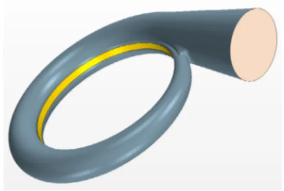
The operating parameters at design point and the geometrical parameters of the standard turbine are presented in Table 1 and Table 2. The geometry of the turbine and the scroll housing are presented in Figures 1 and 2. The performance of the turbine fed with air are computed with the CFD model presented in section 4.1.
Fig. 1: Turbine wheel Fig. 2: Scroll housing
3. Turbine operating point adaptation for working fluid
3.1. Assumption
Heat sink is the ambient air at temperature between 20 and 40°C. Heat source is a parabolic through fed with diathermic oil. Depending on the technology of the panel and the concentration factor, the oil temperature can range from 90°C to 250°C. A temperature difference of 5°C with the evaporating and condensing temperatures will be ensured in the heat exchangers as well as a subcooling of 5°C in the condenser. The temperatures difference may seem quite high and they would be easily reduced by improving the heat exchanger sizing. However this would add extra cost to the system.
The operating point of the turbine with the ORC working fluid is searched in order to ensure:
• Same density ratio: Γ = ρ0 air
ρ2 air =2.542
• Same isentropic efficiency: ηis=0.78
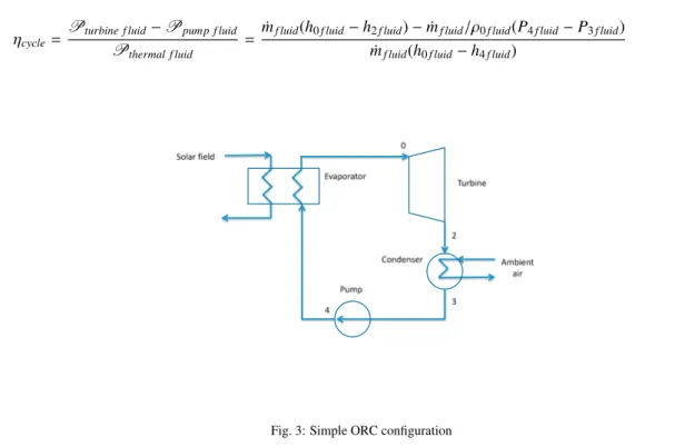
The efficiency of the thermodynamic cycle created with the turbine adaptation need to be evaluated. A simple ORC configuration is considered with only the solar heat collector, evaporator, condenser, pump and and turbine (see Figure 3). The power consumption of the oil circulating pump is negligible. The losses due to the cooling fan would depend on the amount of heat to dissipate and the temperature difference of the air flow. They have been neglected in this study. A proper estimation of theses would require the calculation of the air condensor parameters and might slightly change the results. The cycle efficiency is then expressed with eq. (1). This will allow for the determination of the operating point featuring the best thermal efficiency.
ηcycle= Pturbine f luid− Ppump f luid
Pthermal f luid =
˙mf luid(h0 f luid− h2 f luid) − ˙mf luid/ρ0 f luid(P4 f luid− P3 f luid)
˙mf luid(h0 f luid− h4 f luid) (1)
Fig. 3: Simple ORC configuration
3.2. Procedure
Starting with fixed inlet pressure P0 f luidand inlet temperature T0 f luid, the operating point of the turbine will be fully
determined applying the following procedure:
1. Compute a0 f luid, ρ0 f luidand h0 f luidwith CoolProp [9] from P0 f luidand T0 f luid
2. Compute Nf luid=a0 f luid/a0airNair
3. Compute U1 f luid=R1Nf luid 30π
4. Compute ∆his f luid=−U21 f luid
5. Compute h2 f luid=h0 f luid+ ∆his f luidηis
6. Compute ρ2 f luid= ρ0/Γ
7. Compute P2 f luid, T2 f luidwith CoolProp from ρ2 f luidand h2 f luid
8. Compute ˙mf luid= ˙mairρρ0 f luid0air
Nf luid Nair
As the evolution in the volute has not been modeled, the fluid entering the radial impeller is assumed to be tangent
to the blades. In step 4, considering a radial turbine the inlet tangential velocity V1θis assumed equal to the peripheral
3.3. Fluid selection
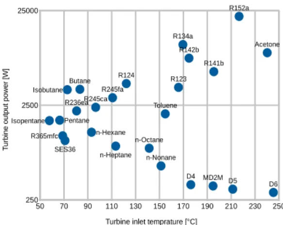
The operating point adaptation has been applied for different fluids. For each fluid the point providing the maximum thermal efficiency is stored. Figures 4 to 7 present the thermal efficiency versus the inlet temperature for different inlet pressure. For each fluid, for a given inlet pressure, the efficiency curves are limited on the left by the saturation temperature. It can be noticed, for example that for SES36 with an inlet pressure of 1 bar, the fluid evaporates at 36°C which is the limit of the curve and give an efficiency of 4.155%. On the right hand side, the graphs are limited by the maximum temperature of the fluid. For SES36 (Fig. 4) and R245fa (Fig. 5), an optimum set of inlet temperature and pressure can be found in the range between saturation temperature and maximum temperature. For R134a and R152a similar behavior can be noticed but the maximum thermal efficiency is located next to the maximum temperature at higher inlet pressure. Contrary to SES36 and R245fa, these two fluids have a wet saturation curve. For each fluid, the operating parameters for the point with the best thermal efficiency have been kept. Figure 8 to 11 present the influence of the inlet temperature on cycle efficiency, output power, rotational speed and condensation temperature. The best efficiency is given by R152a with 6.7% with an inlet temperature of 216.6°C. Siloxanes fluids give the lowest cycle efficiency.
R245fa and SES36 give respectively 4.9 and 4.3% with an inlet temperature of 110.7°C and 70.9°C. For both fluids, the condensation temperature is approximately 35°C. They produce respectively 3.0 kW at 58,645 rpm and 1.06 kW at 46,519 rpm. Theses two fluids are commonly used for low temperature ORC, so they will be retained for the rest of the study. The cycle realized in T-s diagram are presented in Figure 12 and Figure 13.
4.100 4.150 4.200 4.250 4.300 40 50 60 70 80 90 100 110 120 P=1 bar P=1.25 bar P=1.5 bar P=1.75 bar P=2 bar P=2.5 bar P=3 bar P=3.5 bar P=4 bar C yc le e ffi c ie n c y [ % ]
Turbine inlet temperature [°C] P=4.5 bar Fig. 4: SES36 4.500 4.550 4.600 4.650 4.700 4.750 4.800 4.850 4.900 40 60 80 100 120 140 160 C yc le e ffi c ie n c y [ % ]
Turbine inlet temperature [°C] P=1 bar P=9 bar P=8 bar P=7 bar P=6 bar P=2 bar P=3 bar P=4 bar P=5 bar Fig. 5: R245fa 5.800 6.000 6.200 6.400 6.600 6.800 40 60 80 100 120 140 160 180 200 P=1 bar P=4 bar P=5 bar P=6 bar P=8 bar P=12 bar P=20 bar P=30 bar C yc le e ffi c ie n c y [ % ]
Turbine inlet temperature [°C]
Fig. 6: R152a 5.000 5.200 5.400 5.600 5.800 6.000 40 60 80 100 120 140 160 C yc le e ffi c ie n c y [ % ]
Turbine inlet temperature [°C]
P=1 bar P=4 bar P=6 bar P=8 bar P=10 bar
P=12 bar P=20 bar P=30 bar
Fig. 8: Efficiency vs. inlet temperature Fig. 9: Turbine output power vs. inlet temperature
Fig. 10: Rotational speed vs. inlet temperature Fig. 11: Saturation temperature at turbine outlet pressure vs. inlettemperature
280 290 300 310 320 330 340 350 360 1000 1100 1200 1300 1400 1500 1600 1700 1800 T e m p e ra tu re [ K ] Specific entropy [J/kg]
Fig. 12: T-s diagram - SES36
280 300 320 340 360 380 400 1000 1200 1400 1600 1800 2000 T e m p e ra tu re [ K ] Specific entropy [J/kg]
4. CFD simulations
4.1. Model
The fluid volume of the model is extracted from the wheel presented Figure 1 and associated with the volume of the volute Figure 2. Frozen rotor simulations were carried out using StarCCM+. The mesh used the polyedral mesher with a base size of 2 mm and a prism layer of 2 cells. The total number of cells is 202,736.
A mesh sensitivity analysis has been carried out. On a finer mesh with 735,095 cells. The relative error on the results between the two different meshes is 0.04% on outlet temperature and 0.45% on inlet pressure and torque. Although the mesh is quite coarse, the same mesh will be used for all the simulations, so the results and tendency can be compared.
The simulations used the standard k − turbulence model. For the simulation with the air, the fluid is considered as an ideal gas. For the simulation with SES36 and R245fa, Peng-Robinson EOS is considered. The boundary conditions are mass flow inlet with a fixed temperature, pressure outlet and adiabatic walls.
The convergence is ensured by monitoring residuals decrease and asymptotic behavior of integral values such as inlet pressure, outlet temperature and outlet mass flow rate.
4.2. Results
For the turbine operating with air as an ideal gas, the isentropic efficiency can be easily determined with eq (2)
ηturbine= T2− T0 T2is− T0 (2) with T2is=T0 PP20 γ−1 γ
When operating with organic fluids the computation of the isentropic efficiency is replaced by eq (3). With ∆his=
h0− h2isand h2is=EoS (P2,s0) determined with CoolProp. C is the torque on the shaft.
ηturbine= Psha f t
Pis =
Csha f tω
˙m∆his (3)
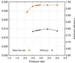
Figure 14 presents the turbine performance curve for original turbine fed with air. The maximum efficiency of the turbine with air at 230,000 rpm is 79.6%. It is a little higher than expected for the design point. The difference is mainly explained by the fact that the CFD model doesn’t take into account the clearance between the wheel and the shroud.
Figure 15 presents the turbine performance curves for operations with SES36 and R245fa. For both graphs the
mass flow rate has been corrected like for air: ˙mcorrected = ˙m√T1/T0/(P1/P0) with P1 =1 bar and T1 =293.15 °C.
The turbine has an optimal operating point with an efficiency of 77.1% with SES36 and of 77.5% with R245fa. This is very close to the best efficiency obtained with air.
0.000 0.005 0.010 0.015 0.020 0.025 0.030 1.0 1.5 2.0 2.5 3.0 3.5 4.0 4.5 0.60 0.65 0.70 0.75 0.80 0.85 0.90 0.95 1.00 C o rr e c te d m a s s fl o w r a te [ k g /s ] A d ia b a ti c e ffi c ie n c y Pressure ratio
Mass flow rate Efficiency
Fig. 14: Original turbine performance with air N = 230, 000 rpm 0.000 0.010 0.020 0.030 0.040 0.050 0.060 0.070 0.080 1.0 1.2 1.4 1.6 1.8 2.0 2.2 2.4 2.6 2.8 0.60 0.65 0.70 0.75 0.80 0.85 0.90 0.95 1.00 C o rr e c te d m a s s fl o w r a te [ k g /s ] A d ia b a ti c e ffi c ie n c y Pressure ratio
SES36 - Mass flow rate R245fa - Mass flow rate
SES36 - Efficiency R245fa - Efficiency
Fig. 15: Adapted turbine performance with ORC fluid
NS ES 36=46, 519 rpm and NR245 f a=58, 645 rpm
Conclusion and perspectives
In this paper a given radial turbine has been studied for its potential to be used as a turbo expander of a solar ORC. A methodology based on simple similitude rules allow for the determination of the best operating while varying the inlet and outlet pressure for different fluids. CFD simulations of the turbine for two fluids confirmed the ability of the method to predict correctly the adapted best operating point.
Further developments will aim to adapt such a turbine and to test it on Arts et M´etiers ParisTech ORC test bench. This will allow to compare CFD and experimental results and to study the off design behavior.
References
[1] S. Quoilin, M. Orosz, H. Hemond, V. Lemort, Performance and design optimization of a low-cost solar organic Rankine cycle for remote power generation, Solar Energy 85 (5) (2011) 955–966.
[2] F. Ferrara, A. Gimelli, A. Luongo, Small-scale concentrated solar power (CSP) plant: ORCs comparison for different organic fluids, Energy Procedia 45 (2014) 217–226.
[3] J. Freeman, K. Hellgardt, C. N. Markides, An assessment of solar-powered organic Rankine cycle systems for combined heating and power in UK domestic applications, Applied Energy 138 (2015) 605–620.
[4] J. Freeman, K. Hellgardt, C. N. Markides, Working fluid selection and electrical performance optimisation of a domestic solar-ORC combined heat and power system for year-round operation in the UK, Applied Energy 186 (2017) 291–303.
[5] E. Casati, A. Galli, P. Colonna, Thermal energy storage for solar-powered organic Rankine cycle engines, Solar Energy 96 (2013) 205–219. [6] C. S. Wong, D. Meyer, S. Krumdieck, Selection and Conversion of Turbocharger As Turbo-Expander for Organic Rankine Cycle ( Orc ), 35th
New Zealand Geothermal Workshop (November) (2013) 1–8.
[7] M. White, A. I. Sayma, The application of similitude theory for the performance prediction of radial turbines within small-scale low-temperature organic Rankine cycles, Journal of Engineering for Gas Turbines and Power 137 (12) (2015) 10.
[8] M. White, A. I. Sayma, Improving the economy-of-scale of small organic rankine cycle systems through appropriate working fluid selection, Applied Energy 183 (2016) 1227–1239.
[9] I. H. Bell, J. Wronski, S. Quoilin, V. Lemort, Pure and Pseudo-pure Fluid Thermophysical Property Evaluation and the Open-Source Thermo-physical Property Library CoolProp, Industrial & Engineering Chemistry Research 53 (6) (2014) 2498–2508.
![Fig. 6: R152a 5.000 5.200 5.400 5.600 5.800 6.000 40 60 80 100 120 140 160Cycle efficiency [%]](https://thumb-eu.123doks.com/thumbv2/123doknet/7385854.215962/7.816.449.755.454.1016/fig-r-a-cycle-efficiency.webp)