Science Arts & Métiers (SAM)
is an open access repository that collects the work of Arts et Métiers Institute of
Technology researchers and makes it freely available over the web where possible.
This is an author-deposited version published in: https://sam.ensam.eu
Handle ID: .http://hdl.handle.net/10985/18203
To cite this version :
Tiago José DOS SANTOS MORAES, Eric SEMAIL, Ngac-Ky NGUYEN - Demagnetization analysis of an open-end windings 5-phase PMSM under transistor short-circuit fault - In: IECON 2019 - 45th Annual Conference of the IEEE Industrial Electronics Society, Portugal, 2019 - IEEE IECON congress - 2019
Any correspondence concerning this service should be sent to the repository Administrator : archiveouverte@ensam.eu
Science Arts & Métiers (SAM)
is an open access repository that collects the work of Arts et Métiers ParisTech
researchers and makes it freely available over the web where possible.
This is an author-deposited version published in: https://sam.ensam.eu
Handle ID: .http://hdl.handle.net/null
To cite this version :
Tiago José DOS SANTOS MORAES, Eric SEMAIL, Ngac-Ky NGUYEN - Demagnetization analysis of an open-end windings 5-phase PMSM under transistor short-circuit fault - In: IECON 2019 - 45th Annual Conference of the IEEE Industrial Electronics Society, Portugal, 2019 - IEEE IECON congress - 2019
Any correspondence concerning this service should be sent to the repository Administrator : archiveouverte@ensam.eu
Demagnetization analysis of an open-end windings
5-phase PMSM under transistor short-circuit fault
Tiago José dos Santos Moraes, Eric Semail, Ngac-Ky Nguyen
L2EP - Laboratoire d’Electrotechnique et d’Electronique de PuissanceUniv. Lille, Centrale Lille, Arts et Metiers ParisTech, HEI Lille, France
E-mail. {tiago.dossantosmoraes; eric.semail; ngac-ky.nguyen}@ensam.eu
Abstract— For an open-end windings integrated Permanent
Magnet Synchronous Machine, the demagnetization of the permanent magnets is analyzed when a transistor is short-circuited and no specific control strategy is adopted. Depending on the temperature, the high currents due to the inverter fault may locally demagnetized the permanent magnets leading to an accelerated aging of the machine and torque loss. A co-simulation, using a Finite Element software for the machine coupled with an average modeling of the transistor, gives interesting local prediction of the machine behavior in healthy and degraded mode.
Keywords— Integrated Motor Drives, PMSM, Demagnetization, Inverter Fault, Transistor Short-Circuit, Electric Vehicles.
I. INTRODUCTION
Multiphase permanent magnet synchronous machine (PMSM) integrated drives are an attractive solution for the electric traction of electric vehicles (EV) and hybrid-electric vehicles (HEV) [1]-[3]. SIVETEC of SIEMENS [4] and i-StARS of VALEO [5] are some examples of commercialized integrated drives. Instead of installing one inverter and one machine with the constraints due to the electric cables and electromagnetic compatibility, the car manufacturer has only one packaging and one thermal cooling. The integrated PMSM can thus increase the torque density and decrease the weight of the electric traction system in comparison to other drives [2]-[12]. However, the compactness of the drive increases the thermal constraints in the machine and in the inverter, because of their thermal interaction [2], [4], [7], [9].
Concerning the inverter, the high temperature Wide-Band Gap (WBG) technology intends to improve the integration of the drive [4]-[9]: high PWM carrier-frequencies with low commutation losses are possible enabling then the use of compact capacitors. Anyway, because of the relative high temperature, WBG transistors are still susceptible to faults as short-circuited transistor , one of the most common and more constraining faults [13]. Short-circuited transistor faults generate very high current amplitude and torque ripple. Multiphase machines with open-end windings supplied by two independent voltage sources (Fig. 1) are tolerant to this kind of fault. It means that the system can keep functioning in degraded mode [14]. In this paper, no specific control strategy is implemented after a fault occurs. It is then considered that the transistors tolerate the high-currents obtained under short-circuited transistor fault during an indefinite period of time.
Concerning the machine, the irreversible demagnetization of the permanent magnets is the most sensitive problem in
Fig. 1: Electric scheme of the drive.
terms of cost when the temperature is too high [12], [15]-[17]. The irreversible demagnetization occurs with a combination of the effects of the magnetic field generated by the winding currents and the temperature of the magnets. The higher is the temperature of the magnets, the lower is the winding current leading to irreversible demagnetization and early aging. Therefore, the torque density of the PMSM, a major advantage for this technology, decreases.
Demagnetization could be avoided by increasing the margin of safety, reducing the maximum operational current or temperature. However, a larger margin of safety raises the drive cost, what is a major constraint in a competitive industry as the automotive one. This paper intends to improve the acknowledge of the machine behavior in its most constraining operating point.
This scenario shows that a short-circuit fault without the appropriate fault control strategy can demagnetize the permanents magnets of the machine’s rotor. In this perspective this paper shows the local impact of this fault on the permanent magnets for different operation temperatures and torque references. Therefore, a co-simulation with ANSYS/MAXWELL software, for the machine finite elements model, and MATLAB/SIMULINK software, for the machine control, was developed.
This paper is organized as follows: Section II presents the chosen machine design and the finite element model. The machine control is depicted in Section III. Section IV describes the transistor short-circuit fault simulation. Section V presents the simulation results and the analysis of the demagnetization of the machine.
II. FINITE ELEMENTS MODEL OF THE 5-PHASE PMSM The chosen machine is a 5-phase PMSM with 20 slots and 14 poles (Fig. 2 and Fig. 3), whose characteristics are presented in Table I. As mentioned before, the multiphase machines are tolerant to the inverter faults analyzed in this paper [10], [18]. The rotor topology and magnets were chosen
This work has been achieved within the framework of CE2I project. CE2I is co-financed by European Union with the financial support of European Regional Development Fund (ERDF), French State and the French Region of Hauts-de-France.
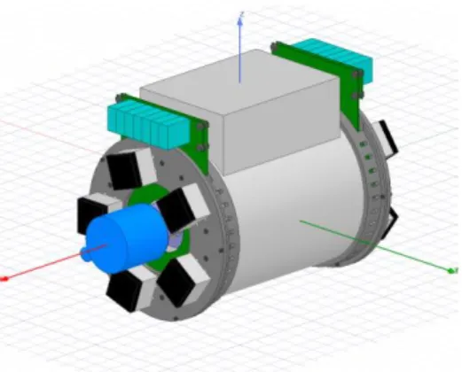
Fig. 2: 3D representation of the machine and the integrated inverters.
Fig. 3: 2D Finite Elements Machine Model with the permanent magnets in orange and the windings in red.
TABLE I.MACHINE CHARACTERISTICS
𝑃𝑛𝑜𝑚 10 kW
𝜔𝑛𝑜𝑚 750 rad/s
𝐼𝑛𝑜𝑚 45 A
𝐾𝑓𝑒𝑚1 4,5 V/rad/s
𝐾𝑓𝑒𝑚3 0,5 V/rad/s
TABLE II.NDFEBN38SH CHARACTERISTICS AT 20°C
𝐵𝑟 1,26 𝑇
𝐻𝐶𝐵 947 𝑘𝐴/𝑚
𝐻𝐶𝐽 1592 𝑘𝐴/𝑚
𝛼(𝐵𝑟) −0.12 %/°𝐶
𝛽(𝐻𝐶𝐽) −0.535 %/°𝐶
considering the irreversible demagnetization risk among other industrial and EV application criterions.
The poles are composed by rare earth NdFeB N38SH magnets, whose characteristics and B x H curve are respectively presented in Table II and Fig. 4. It is well known that rare earth magnets have a high magnetic field density, what increases the power density of the PMSM, but they are expensive [12], [15]-[17]. Another important characteristic of the rare earth magnets is their relative low sensibility to temperature, what is directly related to the irreversible demagnetization risk [11], [12], [15], [17]. Among the most common rare earth magnets, the NdFeB has one of the highest magnetic field density. Concerning, the temperature sensibility, SmCo magnets are less sensitive than NdFeB magnets, but they are even more expensive. N38SH is the grade of the magnet and is also related to the magnetic and thermal performance of the magnets and is related to the
Fig. 4: Polarization J versus Demagnetisation field H characteritics of N38SH magnets
presence of other very expensive rare earth elements in the magnets as the Dysprosium (Dy). A higher concentration of Dy lowers the thermal sensitivity of the magnets but increases its cost [12]. The N38SH grade was chosen because is classified as a “super-high” temperature magnet and the irreversible demagnetization is improbable when the magnets temperature is under 100°C.
The magnets are buried in the rotor in radial disposition called spoke. Concerning the magnetic aspect of this topology, the major advantage is the relative protection of the magnets from the demagnetizing field generated by the windings’ currents [11]. The closer a magnet is from the windings, the more susceptible it is to be irreversibly demagnetized. However, the further the magnet is from the air gap, the lower is its contribution to the torque generation. Concerning, some industrial and EV applications aspects, it is important to mention that this topology is relatively easy to assemble and allows a large speed range thanks to a flux-weakening strategy.
The simulations presented in this paper does not show a temperature evolution, but several simulations with different temperatures that are constant during the whole simulation period. Therefore, each simulation considers a different non-linear B x H characteristic of the NdFeB N38SH between 100°C and 180°C as shown in Fig. 4.
III. MACHINE CONTROL AND CO-SIMULATION
Fig. 5 shows the control scheme of the system. All the control was developed in MATLAB/SIMULINK and send to ANSYS/MAXWELL via the SIMPLORER application. In the SIMPLORER application, the inverter is represented as controlled voltage sources. Finite Element model simulation can be really long and the representation of the transistors would highly increase the simulation duration due to the relative high commutation frequency.
The machine is vector current controlled. The control was developed considering the decomposition of the 5-phase machine in 3 fictitious machines: phase main machine, 2-phase secondary machine and a homopolar one [19]. In this decomposition, each fictitious machine independently interacts to different current and back electromotive forces (Back-EMF) harmonics as shown in Table III. The torque generated by the real machine is the sum of the torque generated by each one of the fictitious ones.
Fig. 5: Co-simulation of a vector controled PMSM.
TABLE III. HARMONICS DISTRIBUTION OF THE FICTITIOUS MACHINES OF A
5-PHASE MACHINE
Fictitious Machines Harmonics
Main 1st, 9th, … 5h±1
Secondary 3rd, 7th, … 5h±2
Homopolar 5th, 5h
The control used on this paper is a vector control with the Maximum Torque Per Ampere (MTPA) strategy [20].That means that the torque distribution between the main machine and the secondary one respects the same ratio of the Back-EMF amplitude of the 1st and 3rd harmonics.
IV. FAULT MODE SIMULATION AND FAULT CONTROL STRATEGY
Finite elements simulations can take relative long time to execute one time-step. Consequently, the simulation of a transistor can be extremely time-consuming due to its commutating frequency on the order of 10kHz. The solution in order to considerably reduces the simulation time is to replace the commutating inverter-leg by an equivalent mean value model. Fig. 6 and Fig. 7 respectively present the commutating model and the mean value model for one phase of the machine.
Iron losses and the skin-effect on conductors are directly related to the frequency of the current components[21]-[23], impacting on the machine total losses and temperature. However, the thermal time constant is much higher than the electric one, allowing to neglect the thermal variation during the simulation period and the high frequency current as well.
A. Mean value model in healthy mode
As mentioned in the previous section, the transistors are represented as voltage sources (Fig. 7). The voltages of these equivalent sources are calculated as follows.
𝑉𝑎= 𝑉𝑎1− 𝑉𝑎2 (1) 𝑉𝑎= 𝑉𝑎𝑛1− 𝑉𝑎𝑛2+ 𝑉𝑛𝑛 (2) 𝑉𝑎1= 𝑉𝑎𝑟𝑒𝑓 2 + 𝑉𝐷𝐶 2 (3) 𝑉𝑎2= − 𝑉𝑎𝑟𝑒𝑓 2 + 𝑉𝐷𝐶 2 (4) 𝑉𝑛𝑛= 𝑉𝑛1− 𝑉𝑛2 (5) 𝑉𝑛𝑥= 1 5(𝑉𝑎𝑥+ 𝑉𝑏𝑥+ 𝑉𝑐𝑥+ 𝑉𝑑𝑥+ 𝑉𝑒𝑥); 𝑥 ∈ [1,2] (6) 𝑉𝑎𝑛𝑥= 𝑉𝑎𝑥− 𝑉𝑛𝑥 (7)
B. Transistor short-circuit simulation
A short-circuit transistor fault occurs when one transistor is blocked at the passing state (Fig. 8). When this occurs, the other transistor of the same block must automatically open, otherwise the voltage source would be short-circuited and the whole system would stop working.
In degraded mode, the voltage of the faulty leg is 𝑉𝐷𝐶 or 0V, if the short-circuit occurred respectively in the up or down transistor as shown in Table IV.
The mean value model was validated by co-simulation in MATLAB/SIMULINK and ANSYS/MAXWELL. Two simulations were achieved, the first one with transistor model which takes into account the commutation effect and component voltage drop. In the second one, the mean value model replaces the transistors by voltage sources.
Fig. 6: Scheme of one phase supplied by an H-bridge and two electric sources of the commutating model.
Fig. 7: Scheme of one phase supplied by two equivalent controlled voltage sources of the mean value model.
Fig. 8: Scheme of one phase supplied by an H-bridge during the short-circuit of 𝑆𝑎1𝑢𝑝.
TABLE IV:VOLTAGE OF THE FAULTY INVERTER LEG X DEPENDING ON THE FAULTY TRANSISTOR
Faulty transistor 𝑽𝒂𝒏
𝒙 𝑽𝒂𝒙
Up 𝑉𝐷𝐶 𝑉𝐷𝐶+ 𝑉𝑛𝑥
Fig. 9 and Fig. 10 present the currents respectively obtained with the commutating model and the mean value model. Both graphics present a typical behavior of this drive under a short-circuit transistor fault [14]. The current is well-balanced in normal mode, contrary to the degraded mode, in which each phase has a different amplitude and constant component. Fig. 11 shows in the same graphic the torque obtained by both commutating and mean value models in healthy and in degraded mode. The unbalanced currents generate torque oscillation in degraded mode.
The current amplitude and the generated torque on both normal and degraded mode are similar, validating then the mean value model for the analysis proposed in this paper. The main difference between both models is the presence of the high frequency component, whose impact on the system is mostly on the copper losses, due to the skin and proximity effects, and iron losses as already mentioned. Even if the losses due to the high frequency component are neglected in the mean value model, this will not significantly impact the
Fig. 9: Phase currents before and after the occurrence of a short-circuit transistor fault in phase A for the commutating model at 100°C.
Fig. 10: Phase currents before and after the occurrence of a short-circuit transistor fault in phase A for the mean value model at 100°C.
Fig. 11: Torque obtained by co-simulation with commutating model and mean value model at 100°C.
demagnetization analysis. No temperature variation is considered because of the high thermal time constant in comparison to the electric one.
V. DEMAGNETIZATION ANALYSIS
The following tests were achieved for different temperatures and different torque references. The analyzed conditions are:
Temperature: 100°C, 120°C, 150°C and 180°C; Torque reference: 20 Nm, 30 Nm and 40 Nm; Fig. 12 and Fig. 13 present some results obtained in degraded mode with no specific control applied after the occurrence of the fault.
The consequences of the fault are high amplitude and unbalanced currents and high torque ripple. As the currents are unbalanced, a whole mechanical turn of the rotor is needed in order to obtain the maximum demagnetization of the permanent magnets.
For the same magnet, pointed out in Fig. 14, the polarization map in healthy and faulty mode are shown in Fig. 15 and Fig. 16. As the polarization map depends on the rotor position, the maps shown in this paper are the one with the lowest polarization values. It is possible to define the parts of the magnet that are not (red), partially (yellow, green and turquoise) or totally (dark blue) demagnetized. Fig. 17 show the relation between the colors and the demagnetization curve.
Fig. 12: Current in healthy and degraded mode for a torque reference of 30 Nm and 150°C obtained by co-simulation.
Fig. 13: Torque in healthy and degraded mode for a torque reference of 30 Nm and 150°C obtained by co-simulation.
Fig. 14: Localisation of the analyzed magnet on the machine.
Fig. 15: Magnetisation map of a magnet in worst case during healthy mode 150°C and 40Nm.
Fig. 16: Magnetisation map of a magnet in worst case during degraded mode for 150°C and 40Nm.
Fig. 17: Colour code of the magnetisation map for 150°C
As expected, the demagnetized part of the magnets is larger in degraded mode because of the high amplitude of peak currents. As well, the demagnetized part of the magnet is the part that is close to the air gap and, consequently, to the magnetic field generated by the winding currents. It is normal that a small part of the magnets is partially demagnetized even in healthy mode. This can be avoided by applying an air barrier [11].
Analyzing the generated torque for the same currents reference is a more objective way to evaluate the impact of the demagnetization. The current reference and the control are the same in normal and degraded mode, but the Back-EMF is impacted by the demagnetization. The demagnetization will lower the generated torque for the same current reference. Table V present the average torque in healthy and degraded mode for different temperatures and current reference.
If the characteristics of the magnets were constant, the torque generated by the machine would be the same as the reference, independent of the current amplitude or temperature. However, the results obtained show that the difference between the generated torque and the reference increases if the temperature or the reference are higher. At 180°C the torque loss is too high in comparison with the other temperatures, showing though that the magnets are already severely demagnetized in normal mode.
When analyzing the torque in degraded mode the torque losses increases because the current amplitudes are higher, consequently generating a more intense demagnetization field. For the same temperature, the degradation of the torque in degraded mode in comparison to the normal mode is almost constant for the different torque references. For example, at 120°C, the torque in degraded mode is around 5% lower than in healthy mode. On the other hand, it is possible to see that the torque losses can significantly increases with the temperature, as the torque reduction in degraded mode in comparison with normal mode is around 9% and 13% at 150°C and at 180°C respectively.
The results of Table V are not only related to irreversible demagnetization. As the current amplitudes are higher in degraded mode in comparison to healthy mode, some parts of the magnets are reversibly demagnetized, reducing though the torque generation. It would be possible separate the percentage of the torque losses related to the irreversible and to the reversible demagnetization. However, if no reconfiguration strategy is applied in order to reduce the current amplitudes in degraded mode, the reversible demagnetization will still impact the torque generation.
TABLE V:MEASURED TORQUE RESULTS IN NORMAL AND DEGRADED MODE AND THE TORQUE LOSS PERCENTAGE IN COMPARISON TO THE TORQUE
REFERENCE. Normal Mode 22 Nm 33 Nm 44 Nm 100°C 21,87 (-1%) 31,68 (-4%) 40,31 (-8%) 120°C 21,40 (-3%) 30,99 (-6%) 39,41 (-10%) 150°C 20,62 (-6%) 29,77 (-10%) 37,72 (-14%) 180°C 15,43 (-30%) 22,20 (-33%) 27,38 (-38%) Degraded mode 22 Nm 33 Nm 44 Nm 100°C 20,84 (-5%) 30,23 (-8%) 38,52 (-12%) 120°C 20,40 (-8%) 29,57 (-10%) 37,64 (-14%) 150°C 18,39 (-16%) 26,98 (-18%) 33,54 (24%) 180°C 12,41 (-44%) 17,74 (-46%) 21,88 (-50%)
VI. CONCLUSION
This paper analyzes the operation in degraded mode of 5-phase open-end windings PMSM when functioning in relative high temperature due to environmental constraints. Co-simulation using a functional software and a finite elements software were used in order to consider the transistor under a short-circuit transistor fault and of the of the rotor permanent magnets under demagnetization respectively. The obtained results show the consequences of the transistor and magnet faults on the torque generation, for then defined the limits of the operation point for the analyzed machine and reduce the margin of security of the system.
Without applying a specific fault control strategy, the torque reduction seems inevitable at high temperature. At 120°C, the torque lowers of 5% in comparison to the torque generated in normal mode what could be tolerate depending on the applications constraints.
ACKNOWLEDGMENT
This work has been achieved within the framework of CE2I project. CE2I is co-financed by European Union with the financial support of European Regional Development Fund (ERDF), French State and the French Region of Hauts-de-France.
REFERENCES
[1] P. Brockerhoff, W. Schon, P. Blaha, P. Vaclavek, and Y. Burkhardt, « Disc inverter in highly integrated 9-phase drivetrain for E-mobility », 2015 17th European Conference on Power Electronics and Applications (EPE'15 ECCE-Europe), Geneva, Switzerland, 2015, pp. 1-9.
[2] J. Wettlaufer, H. Borcherding, F. Klute, and T. Jonsky, « A compact servo drive: Five phase, air cooled, with highly integrated inverter for industrial use », European Conference on Power Electronics and Applications (EPE’15 ECCE-Europe), Geneva, Switzerland, 2015, p. 1-10.
[3] S. Norrga, L. Jin, O. Wallmark, A. Mayer, and K. Ilves, « A novel inverter topology for compact EV and HEV drive systems », Industrial Electronics Society (IECON 2013), Vienna, Austria, 2013, p. 6590-6595.
[4] Siemens.com, “Volvo C30 - Electric Siemens fleet in cooperation with Volvo Car Corporation”, 2015. [Online]. Available: https://w3.siemens.com/topics/global/de/elektromobilitaet/PublishingI mages/home/pdf/Siemens-Volvo-C30-Electric_EN.pdf. [Accessed : 03 April 2019]
[5] Valeo.de, « System – Stop-Start : Valeo reduces CO2 emissions with inovative powertrain systems”, 2017. [Online]. Available:
http://www.valeo.de/en/our-activities/powertrain-systems/technologies/systems-stop-start-362.html. [Accessed: 03 April 2019]
[6] T. M. Jahns and H. Dai, « The Past, Present, and Future of Power Electronics Integration Technology in Motor Drives », CPSS Transactions on Power Electronics and Applications, vol. 2, no 3, p.
197-216, sept. 2017.
[7] T. Keim, « Codesigning Motors and Solid-State Drives [Happenings] », IEEE Power Electronics Magazine, vol. 4, no 2, p.
12-16, jun. 2017.
[8] R. Adebe, G. Vakil, G. Lo Calzo, T. Cox, S. Lambert, M. Johnson, C. Gerada, and B, Mecrow, « Integrated motor drives: state of the art and future trends », IET Electric Power Applications, vol. 10, no 8, p.
757-771, sept. 2016.
[9] S. M. Lambert, B. C. Mecrow, R. Abebe, G. Vakil, and C. M. Johnson, « Integrated Drives for Transport - A Review of the Enabling Thermal Management Technology », Vehicle Power and Propulsion Conference (VPPC’15), Montreal, QC, Canada, 2015, p. 1-6.
[10] A. M. El-Refaie, « Integrated electrical machines and drives: An overview », International Electric Machines & Drives Conference (IEMDC’2015), Coeur d’Alene, ID, USA, 2015, p. 350-356. [11] M. Kimiabeigi, J. D. Widmer, R. Long, Y. Gao, J. Goss, R. Martin, T.
Lisle, J. M. Soler Vizan, A. Michaelides, and B. Mecrow, « High-Performance Low-Cost Electric Motor for Electric Vehicles Using Ferrite Magnets », IEEE Transactions on Industrial Electronics, vol. 63, no 1, p. 113-122, jan. 2016.
[12] S. von Malottki, M. Gregor, A. Wanke, and K. Hameyer, « Magnet design based on transient behavior of an IPMSM in event of malfunction », in 2014 International Conference on Electrical Machines (ICEM), Berlin, Germany, 2014, p. 1262-1266.
[13] Wenping Cao, B. C. Mecrow, G. J. Atkinson, J. W. Bennett, and D. J. Atkinson, « Overview of Electric Motor Technologies Used for More Electric Aircraft (MEA) », IEEE Transactions on Industrial Electronics, vol. 59, no 9, p. 3523-3531, sept. 2012.
[14] N. K. Nguyen, F. Meinguet, E. Semail, and X. Kestelyn, « Fault-Tolerant Operation of an Open-End Winding Five-Phase PMSM Drive With Short-Circuit Inverter Fault », IEEE Transactions on Industrial Electronics, vol. 63, no 1, p. 595-605, jan. 2016.
[15] J. Lee, K.-D. Lee, W.-H. Kim, and C.-S. Jin, « Local demagnetisation analysis of a permanent magnet motor », IET Electric Power Applications, vol. 9, no 3, p. 280-286, mar. 2015.
[16] J. Pyrhonen, S. Ruoho, J. Nerg, M. Paju, S. Tuominen, H. Kankaanpää, R. Stern, A. Boglietti, and N. Uzhegov, « Hysteresis Losses in Sintered NdFeB Permanent Magnets in Rotating Electrical Machines », IEEE Transactions on Industrial Electronics, vol. 62, no 2, p. 857-865, feb.
2015.
[17] J. D. McFarland and T. M. Jahns, « Investigation of the Rotor Demagnetization Characteristics of Interior PM Synchronous Machines During Fault Conditions », IEEE Transactions on Industry Applications, vol. 50, no 4, p. 2768-2775, jul. 2014.
[18] M. Z. Islam, A. K. M. Arafat, and S. Choi, « Determining the operating region for demagnetization-free fault tolerant control of multiphase PMa-SynRM », in 2018 IEEE Applied Power Electronics Conference and Exposition (APEC), San Antonio, TX, USA, 2018, p. 198-204. [19] E. Semail, A. Bouscayrol, and J.-P. Hautier, « Vectorial formalism for
analysis and design of polyphase synchronous machines », The European Physical Journal Applied Physics, vol. 22, no 3, p. 207-220,
jun. 2003.
[20] X. Kestelyn, and E. Semail, « A Vectorial Approach for Generation of Optimal Current References for Multiphase Permanent-Magnet Synchronous Machines in Real Time », IEEE Transactions on Industrial Electronics, vol. 58, no 11, p. 5057-5065, nov. 2011. [21] S. Xue, J. Feng, S. Guo, Z. Chen, J. Peng, W. Q. Chu, P. L. Xu, and Z.
Q. Zhu, « Iron Loss Model for Electrical Machine Fed by Low Switching Frequency Inverter », IEEE Transactions on Magnetics, vol. 53, no 11, p. 1-4, nov. 2017.
[22] A. Młot, M. Korkosz, P. Grodzki, and M. Łukaniszyn, « Analysis of the proximity and skin effects on copper loss in a stator core », Archives of Electrical Engineering, vol. 63, no 2, p. 211-225, june 2014.
[23] S. Iwasaki, R. P. Deodhar, L. Yong, A. Pride, Z. Q. Zhu, and J. J. Bremner, “Influence of PWM on the proximity loss in permanent magnent brushless AC machines,” IEEE Trans. Industrial Applications Vol. 45, no. 4, pp. 1359-1367, 2009.