Science Arts & Métiers (SAM)
is an open access repository that collects the work of Arts et Métiers Institute of
Technology researchers and makes it freely available over the web where possible.
This is an author-deposited version published in: https://sam.ensam.eu
Handle ID: .http://hdl.handle.net/10985/8403
To cite this version :
Von Dim NGUYEN, Patrick MARTIN, Laurent LANGLOIS, Jean-Baptiste CROUE - Product design-Process selection-Process planning Integration based on Modelling and Simulation - In: Joint conference on Mechanical, Design Engineering and Advanced Manufacturing, France, 2014-06-18 - Research in Interactive Design - 2014
based on Modelling and Simulation
Von Dim Nguyen 1, Patrick Martin 2, Lau rent Langlo is 2 , Jean Baptiste Croué 2
(1) : LASMIS Laboratory, Un iversity of Technology of Troyes, 12 rue Marie Curie – CS
42060 – 10004 Troyes Cedex, France
Phone:+33325715702 E-mail : [email protected]
(2) : LCFC Laboratory, Arts et Métiers ParisTech, 4 rue Augustin Fresnel, Metz Technopole, 57078 Metz Cedex 3, France
Phone:+33387375465
E-mail : {patrick.martin,
laurent.langlois,jean-baptiste.croue} @ensam.eu Abstract: As a solution for traditional design process
having many drawbacks in the manufacturing process, the integration of Product design-Process selection-Process planning is carried out in the early design phase. The technological, economic, and logistic parameters are taken into account simu ltaneously as well as manufacturing constraints being integrated into the product design. As a consequence, the most feasible alternative with regard to the product’s detailed design is extracted satisfying the product’s functional requirements. Subsequently, a couple of conceptual process plans are proposed relied on manufacturing processes being preliminarily selected in the conceptual design phase. Virtual manufacturing is employed under CAM software to simu late fabrication process of the potential process plans. Ultimately, the most suitable process plan for fabricating the part is recommended based upon a multi-criteria analysis as a resolution for decision making.
Key words: Modeling, Simulation, Product design, Process selection, Process planning.
1- Introduction 1.1 – Context
In a context where it is necessary to respond industrial challenges towards shorter lead times, lo wer cost and better customer satisfaction. Concurrent Engineering (CE) was born as a solution to these issues. The solution of the CE is carried out in a manner that the different tasks in the product design and manufacturing process are integrated and performed at the same time rather than in sequence [S1].
In order to do this, it is essential to take into consideration the product’s specifications and the constraints of manufacturing process in the design phase. Presently, the design process concentrates on the geometric model bu ilt fro m the choice of architecture to respond to the functional requirements of the product. Traditionally, manufacturing process is determined fro m the choices which were assigned in the product definition without taking into consideration of manufacturing
constraints. So the manufacturing time and cost can be higher than the optimal process plan taking into account of manufacturing process and equipment performances. The CAD models merely represent the information in respect to the product’s nominal geo metry after that they might not relate to fabrication process or will cause the difficu lties in process planning. For resolving these problems, Design for Manufacture (DFM) wh ich allows doing simultaneously (Figure 1) the design and manufacturing process choice activities, was proposed by combining the manufacturing information into the product in the product definition stage [BD1]. In order to imp lement the integrated engineering of DFM approach (or min imu m engagement principle or best least commitment), it is fundamental to formalize and structure the knowledge of manufacturing process capabilities with rules and parameters which allow to select fabrication process and define the intermediary states of the product, and conceptual process planning has to be developed as soon as possible in parallel with the design process. Different process plans can be created. Moreover, concurrent engineering design method starts with a target cost for the product which is compared with the estimated cost of the product.
Integrated Design based on Simulation
Figure 1: Concurrent Engineering as expressed by Prime European Region [S1].
In the framework of concurrent engineering and DFM, this paper proposes an approach contributing to integrated design and manufacturing process for a typical part including disk and tube component. This contributes to the development of integrated design tools such as CAD/CAM and CAPP where following constraints are taken into account concurrently:
- Functional constraints: accuracy requirements (perpendicularity and cylindricity …), mechanical behavior, lower weight.
- Geo metry: the part can be made with only one manufacturing process or by assembling one disk and one tube.
- Technical constraints: mach ining, casting, forg ing, assembly process process capabilities.
- Production constraints: single or a couple of parts.
So several parts design and process plans can be obtain and the choice between them is finally calcu lated.
1.2 – Issue and objective
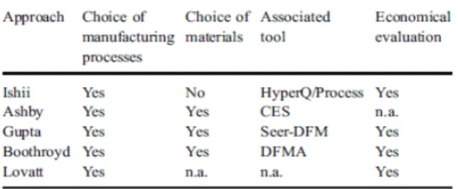
Currently, there are several approaches as well as dedicated softwares for selecting manufacturing processes in order to meet the product’s technical and geometrical characteristics which have been proposed by scientific co mmun ity as shown in Table 1.
Table1: Comparison of the approaches “manufacturing processes selection” [TS1].
However, these approaches and applications only take into account specifications for fin ishing the product. In other words, they just support for selection of manufacturing process corresponding to each features’ specifications belonging to a product, as well as mechanical products being fabricated by a manufacturing process. On the other hand, in practice, process planning with the sequence of manufacturing processes is necessary to carry out for yielding complex parts. In particular, co mplicated parts, for instance, the forward steering part of the Shell Eco-marathon (MASH) vehicle presented in Figure 2 o wning basic shapes such as disk and tube are considered in this approach.
The main objective of our wo rk is to propose an approach of to the development of CAPP systems in wh ich conceptual process plans are generated relied on conditions of elimination of inco mpatible manufacturing processes with the product design.
Figure 2: Various proposed design for forward steering part with combination of disk and tube shape [LC1].
Figure 3: Basic shapes built up the forward steering part
2- Methodology and tool used 2.1 – Methodology
At first fro m the product’s requirements and functional constraints, product’s functional models are obtained. Secondly selection of manufacturing processes being compatible with the part’s characteristics and requirements is get by using dedicated softwares which formalize manufacturing knowledge .
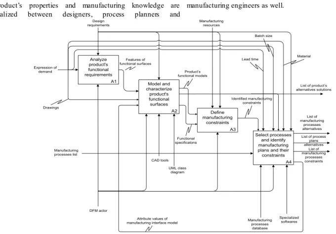
The major activities of the integrated design process expressed as above are rendered with the IDEF-0 diagram in the Figure 4 [FS1]. Where, the main activities are decomposed four activities (A1-A 4).
- A1: Analy ze product’s functional requirements. DFM actor must take into consideration the product’s demands and identify functional surfaces satisfying product’s design requirements.
- A2: Model and characterize product’s functional surfaces. Modeling functional surfaces under the form of usage skin and usage skeleton is realized by CAD tools. Features’ attributes are represented by UML classes. Product’s alternatives solutions are created as the output of this activity.
- A3: Define manufacturing constraints. This activity proposes manufacturing constraints such as tolerance interval (IT), surface roughness (Ra) being oriented according to fabrication method. As a result, these manufacturing constraints will be as the constraints to select manufacturing process.
- A4: Select processes and identify manufacturing plans and their constraints. This activity figures out selected manufacturing processes based on the identified constraints. Corresponding to each constraint, processes which are not eligib le are eliminated by applying specialized software. As a consequence, a list of fabrication processes is proposed as well as attribute values of manufacturing interface model are integrated to product design. Obviously, the integrated design is no longer sequential method; instead of that it is iterative method as synthesis loop. In other words, the information exchanges in relation to the
product’s properties and manufacturing knowledge are realized between designers, process planners and
manufacturing engineers as well.
Figure 4: Main activities of a product’s DFM
With the recommended fabrication processes, conceptual process planning is used in order to propose the alternatives of the part process plans. Subsequently, the proposed process plans are deducted from the production demands including lead-time, batch-size, economic criteria and so forth.
As a result, the potential process plans after deduction are simu lated by using the CATIA and DELMIA software so as to identify manufacturing time as well as foresee problems being able to occur in manufacturing process. Fro m the simu lated results, manufacturing cost estimation is considered applied the ABC (Activity Based Costing) and CE (Cost Entity) methods. Finally, in o rder to support for decision making of the potential process plans in selection of the most suitable plan for fabricating the part, the AHP (Analytic Hierarchy Process) method is used.
2.1 – Tool used
In order to carry out the proposed methodology, several tools are essential to use as follows:
- Modeling languages are used including IDEF0 functional modeling for modeling the product design activities and UML language for modeling the product’s features in which its attributes are presented. Flowchart diagram provided by MS Visio is also used to create conceptual process plans. CES EduPack 2010 and Custompartnet.com software are used for selecting manufacturing processes [AM1]. - Fin ite Element Method (FEM) is served for
analyzing the behavior of the part.
- Online integrated cutting data module of Sandvik firm is used in choosing cutting conditions corresponding types of cutting tools.
- CATIA and DELMIA softwares are applied for modeling the product’s models as well as simu lating manufacturing process. The DPM module of DELMIA is used for defining digital processes and manufacturing resources.
- The ABC (Activity Based Costing) and Cost Entity methods are applied for manufacturing cost estimation [PD1]. Calculations are executed by MS Excel.
- Analytic Hierarchy Process (AHP) method is used for making a decision of multiple criteria.
3- Case study
The case study is a forward steering part, one of the components of the forward direction system of the Shell Eco-marathon (MASH) vehicle as presented in Figure 5. The part must satisfy constraints related to two cylindrical surfaces for wearing the bearings, three holes for fixing the part on the insert and four holes for fixing the stops on the pivot de direction.
It is necessary to take into consideration the weight constraint of the part. Indeed, the principal challenge wh ich needs to be satisfied is that the vehicle travels the furthest on the least amount of energy. A1 Analyze product's functional requirements Design requirements Expression of demand DFM actor A2 Model and characterize product's functional surfaces Features of functional surfaces CAD tools UML class diagram A3 Define manufacturing constraints Product’s functional models List of product’s alternatives solutions A4 Select processes and identify manufacturing plans and their constraints Manufacturing processes list Manufacturing resources Specialized softwares Identified manufacturing constraints Functional specificatons List of manufacturing processes alternatives List of process plans alternatives List of manufacturing processes constraints Manufacturing processes database Attribute values of
manufacturing interface model
Material Lead time
Batch size
Integrated Design based on Simulation
Figure 5: Forward steering part [LC1]. 3.1 – Analysis and part modelling
A featured-based model is applied in this case study for process planning where operations of various types are directly assigned to specific features without considering their interaction. Starting fro m the part’s functional requirements, each design feature is assigned a potential manufacturing process. The specifications of the part are built on the basis of constraints, resources and manufacturing process capabilities.
Figure 6: The forward steering part’s design models
Based on the part’s functional and technical requirements, as well as its constraints with the other components in the system, modeling the part from initial entities relied on its functions to solid models is carried out under CATIA V5 software. More specifically, the functional model on Figure 6.a is generated under the inital entities in which surfaces are modeled fro m functional analysis including the surfaces for mounting bearings and hole surfaces for fitting bolts. From this functional model, several manufacturing processes are selected preliminarily envisaged for fabricating the part. In order to describe the topological entities , solids are added to show clearly the part’s geometrical shapes as shown on Figure 6.b. These components are solely restricted the functional constraints, but they are not mounted together. The part’s completely geometric model created by connecting the functional solids is rendered as on Figure 6.c. This model
expresses fully functional requirements of the part and serves as a starting point for process planning.
3.2 – Process selection
As mentioned in previous section, process selection is realized as soon as the part’s functional surfaces are built under the initial entities. In order to support for preliminary selection of manufacturing processes, CES EduPack 2010 software and Custompartnet.com website are applied in wh ich manufacturing knowledge is formalized. Exp loitation of the two informatics applications is employed based upon the part’s specifications in which specific values of tolerance, roughness, shape and type of material are entered as the input parameters. As a result, a couple of manufacturing processes are reco mmended as processes for fin ishing the part’s functional surfaces satisfying the technical requirements. In particular, the specifications of the functional surfaces are used as the input parameters for selecting manufacturing processes via dedicated software. For CES EduPack 2010 software, tolerance range fitting, roughness and part shape are directly entered as input data to get recommended processes. The input data and results are as shown respectively in Table 2.
Function parameters Input Output parameters Surfaces for mounting bearings Shape: Circular prismatic Tolerance: 0.013 mm Roughness: 3.2
Electric Discharge Wire Cutting Planning/Shaping/Slotti ng Surfaces for mounting bolts Shape: Circular prismatic Tolerance: 0.058 mm Roughness: 6.3 Drilling Milling Planning/Shaping/Slotti ng
Pressing and Sintering Turning/Boring/Parting Table 2: The input data and results from dedicated software
It can be seen that , few eligib le manufacturing processes are proposed for manufacture each functional surfaces of the part. Consequently, a couple of part designs are generated. Particularly, one of the detailed designs is recommended with the input parameters for process planning being shown in Table 3.
The part’s information
Shape group Disk shape with unilateral element - No.213 (ASM Handbook Classification)
Material Alloy Steel: 4140 (AISI/SAE) Roughness Ra 3.2, Ra 6.3
Tolerance IT10, IT6 (ISO) Max wall
thickness 7 mm
Batch-size 20,000 parts per year Table 3: The information of the part 3.3 – Process planning
Generation of process plan is mainly based upon expert system as well as process planner’s knowledge and experience. In practice, it also depends on resource of a
workshop where is intended to manufacture the part. Thereby, conceptual process planning would be done with DELMIA; as a result, virtual manufacturing process would be simulated with the purposes of defining manufacturing time and foreseeing unpredictably issues being able to arise during manufacturing process.
In order to facilitate for generating conceptual process plans, it is necessary to give types of conditions in which manufacturing processes are incompatible with the product’s technical and production requirements. Four types of the conditions have been defined as follo ws [TS1]:
- Conditions of elimination relative to the limits of the manufacturing processes,
- Conditions of elimination linked to the uselessness of the manufacturing processes,
- Conditions of elimination according to the knowledge of an expert,
- Conditions of reco mmandation.
As can be seen from the output’s software in manufacturing process selection, the part’s functional surfaces are finished by machin ing processes in which turning and drilling processes are compatible with the part’s specifications. Fro m the product’s demands, the authors proposed three potential process plans which are eligible to manufacture the part. Furthermore, these process plans are successful candidates after applying the conditions to eliminate incompatib le process plans as well as relying on the expert knowledge. They are visualized on the DELMIA’s PPR (Product-Process-Resource) screen.
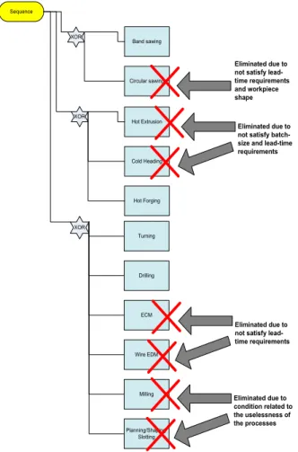
Subsequently, machining simulation is operated with resources existing in the DELMIA’s library such as machines and tools in which cutting conditions are reco mmended fro m the online integrated cutting data module of Sandvik firm. The process plan 2 (Figure 7) is built fro m band sawing and forging processes for workpiece preparation, and drilling and turning for finishing the part. Where, circu lar sawing is eliminated due to not satisfying lead-time and workp iece requirements. Moreover, both hot extrusion and cold heading processes are eliminated because of conditions of elimination of lead-time and batch-size. Again, both ECM and wire EDM processes are eliminated due to lead-time requirement. Milling, planning, shaping and slotting are removed due to the condition related to the uselessness of the processes.
Similarly, surface fin ishing in the process plan 4 is machined with turning and drilling processes. However, the part is separated into two components accounting for cylindrical component and disk component in this case.
Subsequently, the two components are welded together to complete the part. Likewise, conditions of elimination are applied for the process plan 4 shown on the Figure 8.
Figure 7: Generating conceptual process plan 2
Figure 8: Generating conceptual process plan 4 Sequence Hot Extrusion XOR Cold Heading Turning Drilling XOR ECM Wire EDM Milling Planning/Shaping/ Slotting Hot Forging Eliminated due to not satisfy batch-size and lead-time requirements
Eliminated due to not satisfy lead-time requirements Eliminated due to condition related to the uselessness of the processes Band sawing XOR Circular sawing Eliminated due to not satisfy lead-time requirements and workpiece shape
Integrated Design based on Simulation
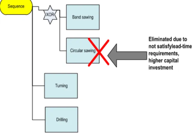
For process plan 5 (Figure 9), band sawing is applied for cutting the workpiece fro m stock. Circular sawing is eliminated because of not satisfying lead-time and higher capital investment requirements. Afterwards, the part would be finished by mach ining process in once fixture.
Figure 9: Generating conceptual process plan 5
Conceptual process plan 5 is created with PPR tree under DELMIA served for simulation of virtual manufacturing process.
After simu lating manufacturing process according to the three process plans for the forward steering part, manufacturing time is synthesized fro m the GANTT diagram with the result as shown Table 4.
3.4 – Manufacturing cost estimation
Manufacturing cost is estimated by using ABC method [MD1]. Where, each manufacturing process plan comprises several processes considered as activities. Thereby, the total manufacturing cost of a process plan is calculated in the following formu la equation:
N i i activity ma
C
C
1 (1)In addition to that, each activity is estimated based on the cost entity approach was proposed by H’Mida [HM1].
Particularly, each cost entity is calculated in the following formula [[HM1]: Cost CE = D x ∑( Rx IRr) (2) Where,
D: Un ique driver chosen for the Cost Entity
R: Resource R consumption coefficient
IRr: Resource R imputation rate
As consequences of the calculations of each process plan, the total manufacturing and operations costs are synthesized as in Table 5.
Table 4: Synthesis of manufacturing process plans
Table 5: Estimated manufacturing cost
4- Process plan selection
In order to make a decision regarding the selection of the most suitable process plan, AHP (Analytic Hierarchy Process) method is used with the goal, criteria and alternatives shown in Figure 10 as below.
Figure 10: The AHP decision hierarchy for the decision
To support for decision makers, the judgment matrices consisting of weights in respect to manufacturing cost and manufacturing time between process plans as well as priorities of them are given in Table 6.
Table 6: Judgement matrices with respect to the criteria
Sequence
XOR Band sawing
Circular sawing Turning Drilling Eliminated due to not satisfylead-time requirements, higher capital investment
Note that pairwise comparisons are assigned the weights relied on the calculated results from the estimation of manufacturing time and manufacturing cost corresponding to the proposed process plans.
It is crucial for decision makers to evaluate the criteria with respect to their impo rtance in reaching the goal through the matrix of co mparison in Table 7 as below.
Table 7: Evaluation of the criteria in reaching the goal
After evaluation and analysis of the priorities between the alternatives, the criteria and the goal, the final score of process alternative groups deduces the synthesized results in Table 8 as follows.
Table 8: The final score of alternatives
Based on the analyzed choice of decision criteria, it can be seen from Figure 11 that the process plan 4 is the most suitable process plan for fabricating the Pivot de Direction with the priority of 0.46, is higher than the others.
Figure 11: The best choice for manufacturing the part
5- Conclusion
The works of this paper carried out are to tackle the issue in terms of the integration of the product detailed design and the conceptual process plan in the early design stage by using numerical modeling and simu lation. As a result, the most feasible process plan is extracted for the case study of the forward steering part. The advantages which get fro m this approach consisting of that we can foresee the problems arising in manufacturing early and correct the design as soon as possible. Consequently, lead-time as well as the product’s cost is decreased significantly. Furthermo re, this approach contributes to collaborative design in which product design and its manufacturing process information supporting for integrated design tools such as CAD/CAM and CAPP.
Nevertheless, a couple of issues are necessary to be taken into account in the future works. In the framework of th is project, the QFD (Quality Function Deploy ment) technique has not used to assess the process quality as well as FMEA analysis has not carried out to assess failure modes and estimate failure cost [HS1]. Due to the fact that the defect rate is considered as zero percent and the project has only considered the manufacturing time and cost of the conceptual process plans. Moreover, it will be interesting to simu late several assembly processes by taking into account of the thermo- mechanical behavior which introduces geometrical constraints for designing the part.
6- References
[AM1 ] M.F. Ashby, F. Michael Materials selection in mechanical design, Butterworth-Heinemann publishers, Oxford ISBN: 9780750643573 (0750643579), 2004
[BD1] G. Boothroyd, P. Dewhurst, W. Knight, “Product Design for Manufacture and Assembly”, Marcel Dekker, ISBN 0-8247-9176-2, 1994
[FS1] S., C. Feng, E. Y. Song, “A Manufacturing Process Information Model for Design and Process Planning Integration”, Journal of Manufacturing Systems, Vol. 22/No. 1, 2003
[HS1] A. Hassan, A. Siadat, J.-Y. Dantan, P. Martin, “Conceptual process planning – an improvement approach using QFD, FMEA, and ABC methods”, Robotics and Computer-Integrated Manufacturing, N°26: 392-401, 2010
[HM1 ] F. H’mida, P. Martin, F. Vernadat, “Cost estimation in mechanical production: The Cost Entity approach applied to integrated product engineering”, International Journal Production Economics 103: 17-35, 2006
[LC1] L. Langlois; J.B. Croué,; A. Delamezière,; P. Martin; S. Zimmer. Reconception de produit en intégrant les contraintes et les potentialités d'un procédé innovant : le FSW , 13e colloque national AIP PRIMECA, 28-30 March, Le Mont-Dore, France,2012
[MD1] P. Martin, J.-Y. Dantan, A. Siadat, Cost estimation and Conceptual Process Planning, Digital Enterprise Technology, Springer Information Systems, ISBN 978-0-387-49863-8, , 243-250, 2007
[S1] Sohlenius G. Concurrent Engineering .Annals of the CIRP 1992; 41:645-655.
[SR1] A. Skander, L. Roucoules, J.-S. Klein Meyer, Design and Manufacturing interface modeling for manufacturing process selection and knowledge synthesis in design, International Journal Advanced Manufacturing Technology 37:443-454, Springer-Verlag,2008
[TS1] A. Thibault, A. Siadat, M. Sadeghi, R.Bigot, P. Martin,”Knowledge formalization for product-process integration applied to forging domain”. International Journal Advanced Manufacturing Technology, 44:1116-1132, Springer Verlag, 2009
![Figure 5: Forward steering part [LC1].](https://thumb-eu.123doks.com/thumbv2/123doknet/7367577.214404/5.893.123.374.100.356/figure-forward-steering-part-lc.webp)