3D PRINTING OF MULTIFUNCTIONAL CHITOSAN-BASED HYDROGELS AND NANOCOMPOSITES
QINGHUA WU
DÉPARTEMENT DE GÉNIE CHIMIQUE ÉCOLE POLYTECHNIQUE DE MONTRÉAL
THÈSE PRÉSENTÉE EN VUE DE L’OBTENTION DU DIPLÔME DE PHILOSOPHIAE DOCTOR
(GÉNIE CHIMIQUE) JUIN 2018
ÉCOLE POLYTECHNIQUE DE MONTRÉAL
Cette thèse intitulée :
3D PRINTING OF MULTIFUNCTIONAL CHITOSAN-BASED HYDROGELS AND NANOCOMPOSITES
présentée par : WU Qinghua
en vue de l’obtention du diplôme de : Philosophiae Doctor a été dûment acceptée par le jury d’examen constitué de :
M. LABERGE LEBEL Louis, Ph. D., président
Mme HEUZEY Marie-Claude, Ph. D., membre et directrice de recherche M.THERRIAULT Daniel, Ph. D., membre et codirecteur de recherche M. ABDELLAH Ajji, Ph. D., membre
DEDICATION
ACKNOWLEDGEMENTS
I have experienced a wonderful time during my Ph.D study in Montreal. I appreciate my supervisors Prof. Marie-Claude Heuzey and Prof. Daniel Therriault for accepting me as their student and giving me an opportunity to do an interesting project. I am very grateful for many things I learnt from them: research attitude, presentation, technical and writing skills. I am grateful to them for their continuous motivation. I am very thankful to them for their scientific supports when I met a problem. I am very lucky to be their student.
I would like to express many thanks to my colleagues and my friends. I have a great time to work with Dr. Marion Maire and Shibo Zou. I have learned a lot of life and research experience from Dr. Kambiz Chizari, Dr. Rouhollah Farahani and Ilyass Tabiai. I would like to thank my colleagues and friends Sampada Bodkhe, Yahya Abderaffai, Changsheng Wang, Shiming Zhang, Rui Tao, Bing Wan, Chao Xu, Hongqiu Wei, Xaver Cauchy, Rajesh Ponnada and Maxime Arguinfor giving me encouragements and advices. I would like to thank my colleagues Mounia Arkoun, Nury Ardila and Renaud Passieuxfor giving me a lot of help when I came to Canada.
I would like to thank the technical assistance from Isabelle Nowlan, Benedict Besner and Meca support team in Polytechnique. I would like to thank Prof. Sophie Lerouge and Prof. Frederick Gosselin for giving me a lot of suggestions and help on my project. I am grateful to the Laboratory of Endovascular Biomaterials in École de Technologie Supérieure. I am thankful to the laboratory of structures and composite materials at McGill university for allowing me to do DMA tests. I would like to thank the Centre for Microscopy and Cell Imaging funded by Concordia University for their help with confocal laser microscopy. I thank the Centre for Characterization and Microscopy of Materials in Polytechnique Montreal. I am very thankful to my financial support from China Scholarship Council (CSC).
Finally, I am very thankful to my parents and my sister. Their unconditional love has made me today.
Sincerely, Qinghua
RÉSUMÉ
La capacité de produire des micro- ou nanostructures complexes dans des matériaux mous est importante pour diverses applications telles que l'ingénierie tissulaire, les capteurs, l'administration de médicaments et les dispositifs médicaux. Dans les tissus vivants, les micro-environnements peuvent affecter l'alignement et l'organisation des cellules, conduisant à la complexité structurelle et fonctionnelle des tissus natifs. Les hydrogels d'origine naturelle sont une classe de matières molles qui sont exceptionnellement attrayantes pour les applications biomédicales, car ils simulent l'environnement aqueux des matrices extracellulaires. Cependant, des structures d’hydrogel d’origine naturelle contrôlées avec précision sont difficiles à obtenir par la plupart des méthodes de fabrication classiques, et même avec la fabrication additive. Malgré les progrès récents dans le domaine de la fabrication additive, des défis importants persistent pour fabriquer des hydrogels avec des structures ordonnées et des propriétés mécaniques et biologiques adéquates pour imiter les tissus natifs.
En outre, les déchets électroniques et la pollution environnementale constituent un problème sérieux en raison de la demande constante d'appareils électroniques plus récents et plus puissants. De nombreux polymères et composants toxiques non biodégradables sont présents dans l'électronique traditionnelle (tels que les condensateurs et les circuits intégrés), et des solvants toxiques (tels que l'isopropanol, l'acétone et le trichloréthylène) sont parfois utilisés dans leur fabrication. Avec l'importance croissante du développement durable, il est de la plus haute priorité pour les entreprises de l'industrie électronique de développer et de fabriquer une électronique respectueuse de l'environnement. Les nano-composites à base de polymères naturels sont d'excellents candidats pour développer la nouvelle génération d'électronique responsable grâce à leur légèreté, durabilité et leur bas coûts. Ainsi, dans ce travail, nous développons un procédé d'impression 3D pour fabriquer des microstructures complexes de polymère naturel, le chitosane, (CS) et de ses nanocomposites.
Ce travail propose des encres à base de CS qui peuvent être fabriquées par impression 3D à température ambiante. La configuration de l'impression 3D est composée d'une étape de translation contrôlée par ordinateur et d'une plate-forme de positionnement à trois axes. L'encre est chargée dans une seringue, qui peut être extrudée à travers une microbuse. Les filaments d'encre sont
déposés sur la plaque pour former une structure couche par couche, où elle subit la solidification du filament par évaporation du solvant aqueux.
Nous démontrons une caractérisation complète des propriétés des encres CS pour l'impression 3D à température ambiante. Les propriétés rhéologiques des encres CS sont analysées par rhéométrie rotationnelle à taux de cisaillement faible et modéré et la viscosité apparente et le comportement en écoulement sont caractérisés par une analyse en rhéométrie capillaire, afin de concevoir une encre aux propriétés rhéofluidifiante pour une impression 3D réussie. Des tests d'évaporation de solvant de différentes compositions d'encre sont menés en observant la réduction de poids des filaments CS extrudés au cours du temps. Puisque différentes structures fabriquées par impression 3D nécessitent des paramètres de traitement particuliers, une cartographie de procédé est créée en prenant en compte des paramètres tels que le diamètre de la microbuse et la concentration d'encre, pour la fabrication réussie de structures CS unidimensionnelles (1D), bidimensionnelles (2D) et tridimensionnelles (3D). Les résultats de la diffraction aux rayons X (XRD) et des propriétés en traction des filaments CS sont également étudiés, montrant différentes propriétés du matériau obtenues après différentes étapes de traitement.
Les échafaudages imprimés en 3D montrent des formes de pores contrôlables (tels que des pores en forme de gradient, carrés et en forme de losange) et une haute résolution de 30 µm. Des échafaudages d'hydrogel microstructurés à surface ridée sont obtenus par une étape de gélification par neutralisation dans l'hydroxyde de sodium. Les échafaudages imprimés et neutralisés montrent des comportements très flexibles et extensibles. La déformation à la rupture des filaments d'hydrogel CS atteint jusqu'à ~ 400% et la résistance maximale est de ~ 7.5 MPa. Les hydrogels microstructurés peuvent guider la croissance des cellules fibroblastiques et induire l'alignement des cellules.
De plus, des nanocomposites constitués de CS en tant que matrice polymère, de nanotubes de carbone à parois multiples (CNT) en tant que nano-renfort et d'un mélange de solvants sont préparés en utilisant un procédé de mélange par broyeur à billes. Les encres nanocomposites CS/CNT sont développées pour présenter une auto-réparation à température ambiante. Les propriétés curatives peuvent être traitées par l'exposition à la vapeur d'eau et le nanocomposite peut restaurer la conductivité électrique et les propriétés mécaniques. L'auto-réparation est rapide, se produisant en quelques secondes après l'endommagement du nanocomposite. L'impression 3D
nous permet de fabriquer des nanocomposites CS/CNT très conducteurs (~ 1450 S/m). L'impression 3D assistée par instabilité est aussi développée pour fabriquer des fibres CS/CNT microstructurées hautement acdaptables, en raison de l'instabilité de l'enroulement de la corde liquide. Des fibres CS/CNT microstructurées présentant des liaisons sacrificielles et une longueur cachée permettent aux nanocomposites d'être très extensibles (déformation à la rupture de ~ 180%). L'extensibilité et la conductivité électrique élevées des fibres CS/CNT permettent de concevoir des capteurs portables. Les capteurs de contrainte personnalisés sont fabriqués par impression 3D assistée par instabilité et ont démontré leur capacité à détecter les mouvements du coude humain. Le nanocomposite CS/CNT peut également être utilisé pour détecter l'humidité due au gonflement du polymère sous une humidité différente de l'environnement.
La nouvelle méthode d'impression 3D d'hydrogels CS et de nanocomposites CS/CNT présentée ici ouvre de nouvelles portes pour concevoir et produire des structures tissulaires 3D à compatibilité topographique, biologique et mécanique ainsi que pour des applications de capteurs de déformations ou d’humidité.
ABSTRACT
The ability to produce complex micro- or nano-structures in soft materials is significant for various applications such as tissue engineering, sensors, drug delivery and medical devices. In tissues or organs, surrounding micro-environments can affect cell alignment and organization that lead to the biological and functional complexity of native tissues. Naturally derived hydrogels are an important class of soft materials, which are exceptionally attractive for biomedical applications since they simulate the aqueous environment of extracellular matrices. However, precisely controlled architectures of naturally derived hydrogels are difficult to obtain through most conventional fabrication methods, and even with three-dimensional (3D) printing. Despite recent progress in the field of additive manufacturing, significant challenges persist to fabricate hydrogels with ordered structures and adequate mechanical and biological properties for mimicking native tissues.
Besides, electronic waste and environmental pollution is a serious issue due to constant demand for newer and more powerful electronics. Many non-biodegradable polymers and toxic components are found in traditional electronics (such as capacitors and integrated circuits), and toxic solvents (such as isopropanol, acetone and trichloroethylene) are on occasion used in their fabrication. With the growing importance of sustainable development, it is of the upmost priority for companies in the electronic industry to develop and fabricate eco-friendly electronics. Natural polymer-based nanocomposites are excellent candidates for developing the next-generation of bio-sustainable electronics due to their lightweight, low-cost, and bio-sustainable properties. Thus, in this work, we develop a 3D printing process to fabricate 3D microstructures of a natural polymer -namely chitosan (CS) - and its nanocomposites.
This work proposes CS-based inks that can be fabricated by 3D printing at room temperature. The setup of 3D printing is composed of a computer-controlled translation stage and a three-axis positioning platform. The ink is loaded into a syringe, which can be extruded through a micronozzle. The ink filaments are deposited on the plate to form a structure in a layer-by-layer manner, where it undergoes filament solidification through solvent evaporation.
We demonstrate a comprehensive characterization of the properties of CS inks for 3D printing at room temperature. The rheological properties of CS inks are analyzed by rotational rheometry at low to moderate shear rate and the process-related viscosity and flow behavior are characterized
by capillary flow analysis, in order to formulate inks with shear thinning behavior for successful 3D printing. Solvent evaporation tests of different ink compositions are investigated by observing the weight reduction of extruded CS filaments with time. Since different structures fabricated by 3D printing require different processing parameters, a processing map is generated by considering parameters such as micronozzle diameter and ink concentration for the successful fabrication of one-dimensional (1D), two-dimensional (2D) and 3D CS structures. The results of X-ray diffraction (XRD) and tensile properties of CS filaments are also investigated, showing different material properties obtained after different processing steps.
The 3D-printed scaffolds show controllable pore shapes (such as gradient, square- and diamond-shaped pores) and a high resolution of 30 µm. Microstructured hydrogel scaffolds with wrinkled surface are obtained through a gelation step of neutralization in sodium hydroxide. The as-printed and neutralized scaffolds show highly flexible and stretchable behaviors. The strain at break of CS hydrogel filaments reaches up to ~ 400% and maximum strength is ~ 7.5 MPa. The microstructured hydrogels can guide fibroblast cell growth and induce cell alignment.
Further, CS-based nanocomposites made of CS as a polymer matrix, multi-walled carbon nanotube (CNT) as a nanofiller and a solvent mixture are prepared using a ball mill mixing method. The CS/CNT nanocomposite inks are developed to exhibit self-healing at room temperature. The healing properties can be processed via exposure to water vapor and the nanocomposite can restore electrical conductivity and mechanical properties. The self-healing is rapid, occurring within seconds after the damage of the nanocomposite. 3D printing enables us to fabricate highly conductive (~ 1450 S/m) CS/CNT nanocomposites. Instability-assisted 3D printing is developed to fabricate high tunable microstructured CS/CNT fibers, due to the liquid rope coiling instability. Microstructured CS/CNT fibers featuring sacrificial bonds and hidden length allow the nanocomposites with high stretchability (strain at break of ~ 180%). The high stretchability and conductivity of CS/CNT fibers enable the nanocomposite to be designed as wearable sensors. The customized strain sensors are fabricated by instability-assisted 3D printing and demonstrate their ability to detect human elbow motions. The CS/CNT nanocomposite can be also used to sense the humidity owing to polymer swelling under different environment humidity.
The novel 3D printing method of tailoring CS hydrogels and CS/CNT nanocomposites demonstrated here opens new doors to design and produce 3D tissue constructs with topographical,
biological, and mechanical compatibility as well as wearable sensor exhibiting strain and humidity sensing ability.
TABLE OF CONTENTS
DEDICATION ... III ACKNOWLEDGEMENTS ...IV RÉSUMÉ... V ABSTRACT ... VIII TABLE OF CONTENTS ...XI LIST OF TABLES ... XIV LIST OF FIGURES... XV LIST OF SYMBOLS AND ABBREVIATIONS... XX
CHAPTER 1 INTRODUCTION... 1
CHAPTER 2 LITERATURE REVIEW... 3
2.1 Chitosan...3
2.1.1 Chitosan hydrogels ...4
2.1.2 Physical chitosan networks ...4
2.1.3 Chemically cross-linked chitosan hydrogels...5
2.2 Electrically conductive nanocomposites ...5
2.2.1 Fundamentals of electrically conductive nanocomposites ...5
2.2.1 Effect of polymers ...7
2.2.2 Effect of processing methods ...8
2.2.3 Properties of CNT ...9
2.3 Self-healing materials...10
2.4 Fabrication techniques used for 3D chitosan structures...13
2.6 3D printing of natural polymers ...18
2.6.1 Inkjet printing ...20
2.6.2 Robotic dispensing ...21
2.7 3D printing of nanocomposites ...23
2.8 Applications of natural polymers and their nanocomposites ...25
2.8.1 Tissue engineering...25
2.9 Summary of literature review...29
CHAPTER 3 RESEARCH OBJECTIVES AND COHERENCE OF ARTICLES... 31
3.1 Research objectives ...31
3.1.1 Specific objectives of the research ...31
3.1.2 Presentation of articles and coherence with research objectives...31
CHAPTER 4 ARTICLE 1: PROCESSING AND PROPERTIES OF CHITOSAN INKS FOR 3D PRINTING OF HYDROGEL MICROSTRUCTURES... 33
4.1 Abstract ...33
4.2 Introduction ...34
4.3 Materials and methods ...36
4.4 Results and discussion...38
4.5 Conclusion...53
4.6 Acknowledgements ...54
4.7 Supporting information ...54
CHAPTER 5 ARTICLE 2: 3D PRINTING OF MICROSTRUCTURED AND STRETCHABLE CHITOSAN HYDROGEL FOR GUIDED CELL GROWTH... 60
5.1 Abstract ...60
5.2 Main text ...61
5.4 Acknowledgements ...70
5.5 Supporting information ...70
CHAPTER 6 ARTICLE 3: 3D PRINTING OF SELF-HEALING AND STRETCHABLE NANOCOMPOSITES SENSORS... 76 6.1 Abstract ...76 6.2 Main text ...77 6.3 Experimental section ...87 6.4 Acknowledgements ...90 6.5 Supporting information ...90
CHAPTER 7 GENERAL DISCUSSION... 96
7.1 3D printing of chitosan...96
7.2 3D printing of chitosan-based conductive nanocomposites ...97
CHAPTER 8 CONCLUSION AND RECOMMENDATIONS... 99
8.1 Conclusion...99
8.2 Recommendations ...100
LIST OF TABLES
Table 2.1: Electrically conductive nanocomposites prepared by different processing methods ...6
Table 2.2: Physical properties of different carbon materials [74]...10
Table 2.3: Various examples of self-healing materials ...12
Table 2.4: Summary of natural polymers fabricated by 3D printing ...19
Table 2.5: Examples of wearable sensors based on nanocomposites ...28
LIST OF FIGURES
Figure 2.1: Structures of CS and chitin. a) CS, b) chitin [36]. ...3 Figure 2.2: Structures of SWCNT (a-d) and MWCNT (e-f). (a) Schematic of an individual helical SWCNT. (b) TEM image showing the cross-section of a bundle of SWCNTs. (c) TEM image of a 1.5 nm diameter SWCNT. (d) A top view of a bundle of SWCNTs. (e) Schematic of an individual MWCNT, showing layers of the tube. (f) TEM image showing the distance between each layer of the tube (0.34 nm) [71]...9 Figure 2.3: Demonstration of self-healing methods including (a) capsule-based, (b) vascular-based and (c) intrinsic-based approaches. (d) performance maps of different self-healing materials on the healing of different volumes and healing rate [78]. ...11 Figure 2.4: Typical CS constructs fabricated using various scaffolding techniques (a) scanning electron microscope (SEM) image of CS scaffold by solvent-casting. (b) SEM image of CS scaffold produced by gas forming [86]. (c) SEM image of CS scaffold by freeze drying [9]. (d) CS scaffold fabricated by freeze drying [87]. (e) electrospun CS nanofibrous membrane [10]. (f) core-shell structured PEO-CS nanofibers by coaxial electrospinning [88]. ...14 Figure 2.5: 3D printing methods classified into light- and ink-based printing methods. (a) Light-based printing: SLA of liquid resin. (b) Light-Light-based printing: selective laser sintering of polymeric or metallic powders. (c) Light-and ink-based inkjet printing. (d) Ink-based fused deposition modelling. (d) Robot dispensing using viscoelastic inks [97]. ...17 Figure 2.6: CS scaffolds fabricated by 3D printing. (a) CS micropattern generated by inkjet printing [104]. (b) CS scaffold fabricated by robotic dispensing [27]. (c) CS scaffold by robotic dispensing [28]. (d) CS scaffold fabricated by cryogenic 3D plotting system [102]. ...21 Figure 2.7: Schematic illustration of solvent-cast 3D printing with a thermoplastic solution. (a) Deposition of the polymer solution through a nozzle. (b) Rapid solvent evaporation post extrusion. (c) Example of a 3D square spiral produced by solvent-cast 3D printing [25]...23 Figure 2.8: 3D nanocomposite macro- and micro-structures fabricated using different 3D printing methods [20]...24 Figure 2.9: Applications of self-healing materials for different wearable devices [17]. ...27
Figure 4.1: Volumetric flow rate as a function of applied pressure for (a) various chitosan inks (6, 8 and 10 wt %) deposited using a 200 µm nozzle, and (b) a 8 wt % chitosan ink extruded using different micronozzle diameters (100, 200 and 330 µm). All inks were prepared using an acidic mixture (40 vol% acetic acid, 20 vol% lactic acid, and 3 wt % citric acid)...39 Figure 4.2: Viscosity with respect to shear rate for different chitosan inks prepared using the acidic mixture: 40 vol% acetic acid, 20 vol% lactic acid, and 3 wt % citric acid (open symbols: data obtained using a cone and plate flow geometry in steady shear; solid symbols: data obtained by extruding chitosan filaments and capillary flow analysis). The dashed curves are fits from the Carreau-Yasuda model where the parameters used are listed in Table 4.1...40 Figure 4.3: Average velocity of ink flow as a function of applied pressure for (a) chitosan solutions (6, 8 and 10 wt %) and (b) a 8 wt % chitosan solution extruded through different micronozzles (diameters: 100, 200, and 330 µm). All the inks were prepared using acidic mixture (40 vol% acetic acid, 20 vol% lactic acid, and 3 wt % citric acid). ...42 Figure 4.4: Solvent content as a function of time for 8 wt % chitosan solutions dissolved in two different solutions (i.e., acetic acid solution: 40 vol% acetic acid; acidic mixture: 40 vol% acetic acid, 20 vol% lactic acid, and 3 wt % citric acid). ...44 Figure 4.5: Process map illustrating the ranges of chitosan contents and nozzle diameters compatible for the fabrication of various types of microstructures. I: zone for 1D filament, II: zone for 2D filament array or 3D structure, III: zone where chitosan solutions lose shape fidelity, IV: zone where chitosan solutions are too dilute for the process, V: zone where chitosan solutions are too viscous to be printed. The letters a-d represent the fabrication parameters of different structures shown in Figure 4.6. Solvent used is the acidic mixture...45 Figure 4.6: (a) close-up SEM image of a chitosan filament, (b) fluorescent microscopy image of a 2D chitosan network, (c) SEM image of a 3D chitosan scaffold with square pore size with top and side views, (d) fluorescent microscopy image of a 3D printed starfish, (e) fluorescent microscopy image of a 3D printed leaf. Inset images in b, c, d and e show CAD models of the 2D network, scaffold, starfish and leaf structures. ...47 Figure 4.7: (a) and (f) CAD models of a shaped-like spider structure. (b-e) Fluorescent microscopy images of “spiders” fabricated using a 10 wt % ink with an acetic acid solution and (g-j) a 10 wt % ink with the acidic mixture after printing 0, 1, 4, and 28 h. (k) CAD model of the scaffold. (l) An
as-printed 30-layer chitosan scaffold fabricated using a 10 wt % ink with the acetic acid solution using 200 µm nozzle and (m) a scaffold fabricated using a 10 wt % ink with the acidic mixture under the same fabrication conditions. (n) The width and thickness reductions of the scaffolds fabricated using chitosan inks (10 wt %) with the acetic acid solution and acidic mixture in Figures l and m over a period of 28 h. ...49 Figure 4.8: (a) SEM images of a 3D printed chitosan scaffold 12 h after printing, and a close-up view of the surface of the filament in the red frame area. (b) SEM images of a neutralized scaffold in the dry state, and a close-up view of the filament featuring longitudinal wrinkles in the red frame area. (c) Confocal images of a neutralized scaffold in the wet state, and fluorescent confocal image of the filament texture in the red frame area. ...50 Figure 4.9: X-ray diffraction patterns. Comparison of chitosan powder, dried chitosan filaments printed using the acidic mixture (40 vol% acetic acid, 20 vol% lactic acid, and 3 wt % citric acid), and dried chitosan filaments prepared using the same acidic mixture after neutralization...51 Figure 4.10: (a) Typical stress-strain curves for chitosan filaments after different processing steps (3P: as-printed chitosan, 3P-D: printed chitosan 72 h after drying, N-W: neutralized chitosan in the wet state, N-D: neutralized chitosan in the dry state). (b) Tensile strength at break, (c) strain at break, and (d) Young’s modulus of chitosan filaments, compared with the chitosan fabricated by other methods including solvent-cast chitosan in wet state (Sc-W) and in dry state (Sc-D), electrospun chitosan in dry state (Es-D), and cryogenically 3D plotted chitosan (Cp-D). A 8 wt % chitosan ink prepared using the acidic mixture was used to fabricate the chitosan filaments. ...53 Figure 5.1: a) Schematic representation of 3D printing of a chitosan ink prepared using an acidic mixture and partially hardened via solvent evaporation. b, i) Optical image of the printing of a 30-layer 3D chitosan scaffold through a 100 µm micronozzle, and ii) optical image of a 10-30-layer chitosan scaffold fabricated with a 100 µm micronozzle and folded using a tweezer. c) Schematic illustration of the neutralization step for yielding physical gelation with hydrophobic interaction and hydrogen bonds to form a chitosan hydrogel scaffold. ...63 Figure 5.2: (a-f) Optical and SEM images of chitosan dried scaffolds with various architectures fabricated through a 100 µm micronozzle: (a-c) Square pattern (Ps = 220 μm × 220 μm, D = 70 μm, L = 30) and (d-f) diamond pattern (S = 300 μm, D = 70 μm, αmin = 45°, L = 30) with top, inclined, and side views. g) 3D reconstruction of a neutralized scaffold (Ps = 200 μm × 200 μm, D
= 100 μm, L = 10) in water imaged using laser scanning confocal microscopy. h) Surface rendering of the hydrated filament in a neutralized scaffold, showing a wrinkled surface using confocal fluorescence imaging after staining with Rhodamine B. i) Surface rendering of the hydrated chitosan film after neutralization (t = 1 mm, L = 10), presenting a smooth surface using confocal imaging...65 Figure 5.3: a) Typical stress-strain curve for as-printed chitosan (surface area = 0.15 mm2) and neutralized chitosan filaments (surface area = 0.22 mm2) in wet state. b) An as-printed chitosan scaffold (Ps = 220 μm × 220 μm, D = 90 μm, L = 10) and a neutralized chitosan scaffold (Ps = 200 μm × 200 μm, D = 130 μm, L = 10) are uniaxially stretched to almost two times its initial width and experiences full recovery after stretching to return to its original shape. ...66 Figure 5.4: a) Fluorescence images of L929 fibroblasts plated on neutralized chitosan scaffolds (Ps = 200 μm × 200 μm, D = 100 μm, L = 10) after 7 days. b) SEM image of L929 fibroblasts adhered on neutralized chitosan scaffolds after 7 days. c) Cell viability on surface of scaffolds and films (t = 1 mm, L = 10) by Alamar Blue assay at 1, 3 and 7 days. d) and e) SEM images of L929 fibroblasts plated on chitosan scaffolds under a higher magnification view of figure b) in the red frame areas. f) Schematic diagram illustrating the procedure used to characterize the alignment angle θ between the orientation of fibroblasts and the main direction of filaments in scaffolds or horizontal line in films. g and h) Fluorescence and SEM images of L929 fibroblasts plated on chitosan films after 7 days. i) Quantification of the orientation of fibroblasts on hydrated chitosan scaffolds and films.
...68 Figure 6.1: (a) CS/CNT ink preparation: CS polymer dilute solution (solvent: acetic acid, citric acid and lactic acid) and CNT were mixed via a ball mixing method. (b) Electrical conductivity of CS/CNT nanocomposites with different CNT contents. The zone at the left of the vertical dashed line represents 3D printable CS/CNT inks with CNT content lower than 30 wt %. (c) A 20-layer scaffold, spider and starfish shaped structures fabricated by the 3D printing method, which undergo solvent evaporation to solidify the structures. (d) Schematic of instability-assisted 3D printing (IA3DP): a CS/CNT fiber with fiber diameter D and contour length L was fabricated with a depositing height H, robot speed Vp and material speed Vt. Photographs of different patterned CS/CNT fibers fabricated from IA3DP under the same condition of H/D = 10, from right to left: straight, meandering, alternating, coiling and overlapping patterns. ...80
Figure 6.2: (a) Optical microscopy images of a CS/CNT fiber at original, damaged and healed states to turn on or off a LED light bulb, and images at a higher magnification showing the damaged and healed regions on the fiber. (b) Schematic illustration of the healing process of a CS/CNT fiber exposed to water vapor: water vapor increases the swelling of the CS polymer and thus favors the chain movement and electrostatic interactions between CA- and CS+. (c) Repeated healing and recovery of electrical properties for five cuts on the fiber. ...81 Figure 6.3: (a) Representative tensile curves of straight and coiling pattern fibers with photographs on the top to show sacrificial bond breakage and hidden length extension of bond α. (b) SEM images of a coiling pattern CS/CNT fiber (30 wt % CNT) with three bonds. (c) Top: high magnification of an original sacrificial bond in c, middle: sacrificial bond in broken and healed (bottom) states. (d) Typical tensile curves of a coiling pattern fiber for original loading with breaking of first bond and healing of the bond. (e) Typical tensile curves of a coiling pattern fiber for original loading with breaking of second bond and healing of the bond. (f) Typical tensile curves of a coiling pattern fiber with breaking and healing of all three bonds. ...83 Figure 6.4: (a) Relationship between RH and electrical resistance for a CS/CNT fiber (10 wt % CNT) as a humidity sensor. (b) Current change for a strain sensor attached to the outside of an elbow to monitor the bending motion of an arm with fully stretched arm (relaxed state) and fully bended arm (bended state). (c) Schematic showing the strain sensor attached on an elbow under relaxed and bended states, and the shape change of the coiling fiber on a CS film under the force of bending the arm. The black curves show the different electronic pathways between original fiber and the fiber under tension. (d) A spider-web-like sensor formed by a coiling pattern CS/CNT fiber (30 wt % CNT) in spiral thread that was deposited on a CS network (dyed in pink) with straight fibers in radical thread. The CS fibers divided the CS/CNT fiber into pieces. This sensor was attached to a transparent PDMS film. (e) Current signals of the whole CS/CNT fiber web in response to breaking four bonds. The inset images show top views of an initial loop and the loop after breaking its sacrificial bond and the black curve shows their different electronic pathways. (f) Current signals of the fiber where one sacrificial bond was broken. ...86
LIST OF SYMBOLS AND ABBREVIATIONS
3D three-dimensional
CS chitosan
TE tissue engineering CNTs carbon nanotubes
DDA degree of N-deacetylation PVA poly(vinly alcohol) HPN hybrid polymer networks IPN interpenetrating networks MWCNT multi-walled carbon nanotubes SWCNT single-walled carbon nanotubes PLA polylactic acid
CA classifications HM healing mechanism HC healing conditions CD conductivity
RM recovery of mechanical property RE recovery of electrical property CO2 carbon dioxide
PCL polycaprolactone 2D two-dimensional
SEM scanning electron microscope PEO poly(ethylene oxide)
SLS selective laser sintering FDM fused deposition modelling M polymer matrix NF nanofillers PM processing methods F flexibility SB stretchability SF self-healing
CHAPTER 1
INTRODUCTION
Background and problematic
The shortage of transplantable organs has become a national crisis and has the disadvantages of high costs, risks of infections from donor pathogens, and graft rejection by the immune system [1, 2]. To overcome these issues, tissue engineering (TE) is emerging as a revolutionary strategy which seeks to restore degenerated or damaged tissues. A particularly appealing strategy in TE is to combine the host’s own cells with polymer based scaffolds [3]. Tissue-engineered scaffolds should be biodegradable, biocompatible, and have temporary mechanical support as well as customized structure [10], to mimic a certain degree of the complexity of native tissues or organs [4]. Natural polymers such as chitosan (CS) are attractive materials to engineer scaffolds, owing to their high cell compatibility [5]. However, CS normally presents weak mechanical properties, especially for its hydrated conditions [5, 6]. Porous CS scaffolds have been fabricated by techniques such as freeze drying and electrospinning, typically based on a random distribution of cells, matrix, and bioactive molecules [7-10]. Controllable cell-organization in scaffold is fascinating for TE to mimic the hierarchical structure of real tissues and organs such as muscles and bones [11-13]. Furthermore, natural polymers are also excellent candidates for developing next-generation of sustainable electronics owing to their lightweight, low-cost, non-toxic, biodegradability and renewable properties [14, 15]. Conductive fillers such as carbon nanotubes (CNTs) can be loaded into natural polymers to form conductive nanocomposites. Self-healing is also a desirable feature for designing electronic materials with the ability to heal damages and extend their lifetime. Self-healing nanocomposites could be used for a wide range of applications such as wearable devices [16, 17], biosensors, electronics [18] and soft robotics [19]. Nanocomposites used in wearable sensors such as strain sensors are mainly used as a thin film [20]. Nanocomposite sensors in a form of film are however not capable of demonstrating very high sensitivity [21].
3D printing, consisting of a computer-controlled translation stage, might address these issues. Recent advances in 3D printing have been developed to fabricate various materials such as ceramics [22], polylactic acid (PLA) fugitive inks [23], concentrated silk fibroin [24], colloidal
suspensions, thermoplastic polymers [25] and hydrogels [26]. Natural polymers composed of polysaccharides and proteins are still challenging for 3D printing, since they may deform or
collapse during the printing process. Prior strategies used in situ gelling or low temperature to solidify the ink filament during the printing process [27-29]. However, they always involve a complicated fabrication process (using a bath or reservoir) and some crosslinkers used during fabrication may be cytotoxic. Several conductive nanocomposite inks have been developed so far [30-33]. However, these inks usually contain toxic organic solvents (e.g., dichloromethane) and/or toxic components. Thus, novel ink design and processing technologies with the dominance of simplicity and “green” processes should be developed for fabricating natural polymers such as CS and based nanocomposites for TE and electronic applications.
Organization of the thesis
This thesis is based on three articles submitted to scientific journals and consists of the following sections:
Chapter 2 provides a literature review on chitosan, its physiochemical properties and applications, on electrically conductive nanocomposites, various fabrication techniques used for CS, 3D printing methods used for natural polymers and nanocomposites and the applications of natural polymers and nanocomposites including TE and wearable devices. Chapter 3 states the research objectives and the coherence between the objectives and articles. The core results of this thesis, in the form of three peer reviewed scientific articles, are presented in the following three chapters. Chapter 4 includes a comprehensive study on the effect of fabrication parameters (applied pressure, robot velocity and nozzle diameter) and CS-related parameters (ink composition, solvent evaporation rate and rheological properties) on the printability and CS filament properties. Chapter 5 focuses on the development of CS inks used to fabricate CS scaffold by 3D printing. Microstructrured CS hydrogels are obtained and can guide cell growth and cell alignment. Chapter 6 shows the development of CS/CNT nanocomposites and investigates their electrical conductivy, along with self-healing and mechanical properties. The nanocomposite inks were used to fabricate microstructured fibers by instability-assisted 3D printing. Microstructured fibers were further developed as humidity and strain sensors. In Chapter 7, a general discussion of the entire thesis is presented. Finally Chapter 8 summarizes the conclusions and the recommendations for future work.
CHAPTER 2
LITERATURE REVIEW
2.1 Chitosan
Chitosan, a natural polymer, can be obtained from crustacean shells (chitin) and fungi [34]. As shown in Figure 2.1(a), it is semi-crystalline polysaccharide and composed of β(1→4) linked D-glucosamine residues with (1→4)-2-acetamido-2-deoxy-β-D-glucan (N-acetyl D-D-glucosamine) and (1→4) -2-amino-2-deoxy-β-D-glucan (D-glucosamine) units [35]. CS is more generally derived from chitin, which is the second most abundant natural amino polysaccharide, through N-deacetylation [14]. Chitin consists of β-(1→4)-N-acetyl-D-glucosamine units (Figure 2.1(b)). The degree of N-deacetylation (DDA) gives the number of amino groups on the skeleton of the CS chain, and the DDA should reach at least 60% for CS [36]. The physical characteristics of CS rely on some main factors: i.e. DDA, molecular weight (average and distribution), the purity, sequence of the acetamido and amino groups and so forth [37].
Figure 2.1: Structures of CS and chitin. a) CS, b) chitin [36].
Much of the potential of CS as a natural compound derives from its physiochemical characteristics. Firstly, the solubility of CS in aqueous solutions is poor due to its stable and crystalline structure, while it is soluble in acidic aqueous solutions below a pH of ~6 (pKa) as the free amino groups of CS can be protonated [38]. The pH-dependent solubility of CS allows the manufacturing process to fabricate products such as fibers and scaffolds [39].
Secondly, CS is the only positively-charged natural polymer with high charge density because of protonation, allowing it to form insoluble ionic complexes with a wide variety of water-soluble natural or synthetic anionic materials [40]. CS can combine with negatively charged drugs for drug delivery [41]. Additionally, the amino groups of CS can make it covalently cross-linked with other
materials [36], and functional groups on CS can be chemically or enzymatically modified to change its physical properties.
Finally, CS exhibits a wide variety of intrinsic properties. Briefly, CS is biodegradable: it can be degraded into non-toxic compounds and be metabolized by enzymes in human body like lysozyme [42], which makes it highly suitable to be implanted or injected in the body. CS is biocompatible providing affinity with cells and biomolecules. CS is also mucoadhesive and acts as an antibacterial agent [43], which makes it possible to use in wound healing [44]. All the interesting intrinsic properties mentioned above allow CS to be an outstanding candidate for biomedical applications.
2.1.1 Chitosan hydrogels
Hydrogels are three-dimensional hydrophilic polymeric networks swollen in water or biological fluids and contain chemical or physical cross-links [45]. Hydrogels can be formed from synthetic and natural polymers including hydrophilic homopolymers and copolymers [46]. CS, as a natural polymer, can form biological hydrogels with high water content that are bendable and soft, and they are capable of reducing the damage to the surrounding living organs or tissues for implantation [5].
2.1.2 Physical chitosan networks
Physically associated CS hydrogels present reversible gelation based on electrostatic interactions, hydrophobic interactions or hydrogen bonding instead of covalent interactions [6]. Protonated CS as a polycation can form physical networks with anionic components by ionic interactions and the formation can be affected by DDA, charge density, concentration and the size of negatively charged molecules [47]. Water-soluble non-ionic polymers are also capable of blending with CS to form hydrogels such as poly(vinly alcohol) (PVA) [48]. CS is capable of being gelled by itself without using any additives by neutralizing the amino groups [49]. Physical gelation of CS solutions was performed and explained by hydrophobic interactions and reduced solubility by adding β -glycerophosphate while heating at neutral pH [50]. CS can also be gelled by dissolving in certain types of acid solutions such as sulfuric acid, oxalic acid and phosphoric acid [51]. Physical CS hydrogels are more compatible without using toxic additives, but the mechanical properties are quite limited and it is difficult to precisely control the hydrogel pore sizes, dissolution and chemical functionalization [5].
2.1.3 Chemically cross-linked chitosan hydrogels
Chemically cross-linked CS networks can be classified into three categories: CS cross-linked alone, hybrid polymer networks (HPN) as well as full- or semi-interpenetrating networks (IPN) [42]. CS can be cross-linked by itself with cross-linkers, such as glutaraldehyde and genipin. The gelation reaction of chemical CS hydrogels is mainly dominated by cross-linkers [52]. Materials involved in HPN are mostly biomaterials that need to be biodegradable, biocompatible and bioadhesive. Semi-IPN contains a non-reacting polymer before cross-linking and is entrapped in CS networks, while full-IPN hydrogels are formed by a sequential strategy including the formation of semi-IPN [53]. Irreversible chemical hydrogels are more stable than physical hydrogels. However, toxic agents or catalyst involved may result in contamination.
2.2 Electrically conductive nanocomposites
2.2.1 Fundamentals of electrically conductive nanocomposites
Nanocomposites (at least one dimension in nanoscale from 1 to 100 nm) featuring electrical conductivity are attractive materials for wide applications such as energy storage [54], sensors and biomedical applications [55]. Electrically conductive nanofillers such as single-walled carbon nanotube (SWCNT), multi-walled carbon nanotube (MWCNT), graphene, metallic nanorods, have been used to fabricate nanocomposites with large surface area, electrical conductivity and nanostructures. As described by percolation theory [56], the nanofiller loading plays a significant role in the conductivity of nanocomposites. The conductivity of nanocomposites is very low (close to the insulative state) at a low nanofiller loading, since the distance of nanofillers in the nanocomposite is larger than the size of nanofillers [57]. A “percolation” pathway is formed by connected nanofillers to suddenly increase the conductivity by several orders of magnitude, when the nanofiller concentration reaches to a critical concentration (called percolation threshold). Table 2.1 shows a collection of conductive nanocomposites prepared by different processing methods. The properties of nanocomposites can be affected by polymer matrix (M), the type of nanofillers (NF) and the processing methods (PM).
Table 2.1: Electrically conductive nanocomposites prepared by different processing methods
MA NF Solvent PM CD
(S/m)@C (wt %)
Structures Applications Ref.
SI AgNP DCM Planetary centrifugal mixing 0.01@68 Hybrid scaffold Tactile sensors [58] EP MWCNT No solvent centrifugal vacuum mixing [email protected] Sponge EMI shielding [59] EP GNP Acetone CO2-assisted mixing 10-5@12 - - [60] PLA MWCNT DCM Mechanical mixing and sonication 23@5 Freeform 3D helix Liquid sensor [31]
PLA MWCNT DCM Ball mill mixing
3800@40 3D scaffold Liquid sensor [32]
PN AgNW Hydrogen chloride Solution mixing 1.03 × 10⁶ Film - [61] CE rGO Methanol, acid hydrolysis Solution mixing [email protected] , [email protected] Membrane - [62] EC GR Cyclohexano ne/terpineol Solution mixing sonication 25600@50 Film Flexible electronics [63]
AF rGO water Mechanical stirring
[email protected] Film Enzyme sensing
[64]
GEL rGO Deionized water Solution mixing 3.78@10 - - [65] CS MWCNT Acetic acid, glycerol, ionic liquid Solution mixing sonication 239@40, 3425@80, Membrane Actuator [66]
CS SWCNT Acetic acid Solution mixing
500@40 Membrane Actuator [67]
CS rGO Acetic acid Ultrasonicati on 6.7 Lamellar structure - [68] Our work MWCNT Acetic acid, lactic acid, citric acid Ball mill mixing 1450@40 Microstruct ured fiber, scaffold Sensors
A: SI: silicone,EP: epoxy,PLA: polylactic acid, PN: polyaniline, CE: cellulose, EC: ethyl cellulose,
GEL: gelatin, AF: amyloid fibril, GEL: gelatin, CS: chitosan, AgNP: silver nanoparticle, MWCNT: multi-wall carbon nanotube, AgNW: silver nanowire, GNP: graphene nanoplatelet, rGO: reduced graphene oxide, GR: graphene, SWCNT: single-wall carbon nanotube, DCM: dichloromethane
2.2.1 Effect of polymers
The type of polymers plays an important role on the electrical properties of nanocomposites. Some polymers show intrinsic conductivity such as polyaniline (PN) [61]. Therefore, nanocomposites prepared by conducting polymer can achieve excellent conductivity. As shown in Table 2-1, maximum conductivity of 1.03 × 10⁶S/m has been demonstrated in PN/AgNW nanocomposite film (thickness of ~ 2.5 μm for the AgNW layer and thickness of ~ 10 μm for the PN layer) at a AgNW areal density of 0.84 mg/cm2. The PN/AgNW nanocomposite was prepared by solution mixing [61]. The polymer may also affect the percolation threshold, since polymer physical properties such as polarity, surface tension and crystallinity have an obvious effect on the
percolation threshold. For example, Nassira et al. demonstrated gelatin/graphene nanocomposite that present an ultralow percolation threshold 3.3 × 10⁻²vol%[65], due to polymer properties and the processing method.
2.2.2 Effect of processing methods
The processing methods have an important effect on the dispersion, orientation, distribution and aspect ratio of nanofillers. Well-dispersed nanofillers in a polymer matrix is important for achieving excellent mechanical properties [63]. Optimized processing method is also necessary for obtaining low percolation threshold [65]. However, for the electrical conductivity, high concentrations of nanofiller play a significant role in obtaining high conductivity [69]. As shown in Table 2.1, solution mixing is the most popular method to prepare nanocomposites based on natural polymers.
Solution mixing allows preparing nanocomposites in three steps: dispersing nanofillers in a solvent, mixing the polymer and casting the nanocomposite as a film. This method always need sonication
[67], ultrasonication [68]or mechanical stirring [64]to mix the solution. The selection of solvent is important to obtain well-dispersed nanocomposites. Lu et al. reported that well-dispersed CS/MWCNT nanocomposite was achieved by adding ionic liquid [66]. Toxic solvents such as methanol [62], cyclohexanone and terpineol [63] may be involved in the formation of nanocomposites, which is not compatible for industries since large amount of solvent needs to be evaporated during the process. Also, this processing method usually results in the structures of nanocomposites including a thin film or a fiber that is limited for potential applications. This method is great to mix polymer and nanofillers at low concentration, but it is not very suitable for processing the solution with high content of nanofillers.
Ball mill mixing is a class of grinding method, which use ceramic balls to mix the materials. The high shear stress generated between the rigid balls helps to disperse the nanofiller in the polymer matrix. It has been developed to produce nanocomposite with high content of nanofillers. For example, Chizari et al. reported PLA/MWCNT nanocomposites with high contents of MWCNTs (up to 40 wt %) formed by ball mill mixing for the application of liquid sensor [32].
2.2.3 Properties of CNT
Carbon nanotubes (CNTs), discovered by Sumio Iijima in 1991, are promising materials due to their superior electrical and mechanical properties [70]. They can be classified into two types: single-walled nanotube (SWCNT) that is made of a single graphite sheet enfolded into a tube (Figure 2.2 a-d); Multi-walled nanotube (MWCNT) that consists of concentrically arranged nanotubes (Figure 2.2 e-f) [71].
Figure 2.2: Structures of SWCNT (a-d) and MWCNT (e-f). (a) Schematic of an individual helical SWCNT. (b) TEM image showing the cross-section of a bundle of SWCNTs. (c) TEM image of
a 1.5 nm diameter SWCNT. (d) A top view of a bundle of SWCNTs. (e) Schematic of an individual MWCNT, showing layers of the tube. (f) TEM image showing the distance between
each layer of the tube (0.34 nm) [71].
CNTs have chemical bonding of sp2 carbon-carbon bonds that provide CNTs with exceptional mechanical properties (i.e., tensile strength of 55-150 GPa [72], Young’s modulus of 1.7-3.6 TPa [73]). Table 2.2 shows the physical properties of several carbon materials. CNT (density of 0.8-1.8 g/cm3) are lighter than other carbon materials such as graphite (density of 1.9-2.3 g/cm3). CNTs also possess remarkable thermal and electrical properties as compared with other carbon materials, as shown in Table 2.2. These properties allow CNTs a wide range of applications such as electronics, sensors, energy storage and aerospace applications.
Table 2.2: Physical properties of different carbon materials [74]
Property Graphite Diamond Fullerene SWCNT MWCNT
Specific gravity (g/cm3) 1.9–2.3 3.5 1.7 0.8 1.8 Electrical conductivity (S/cm) 4000p, 3.3c 10−2–10−15 10−5 102–106 103–105 Electron mobility (cm2/ (V s)) 2.0 ×10⁴ 1800 0.5–6 ∼105 104–105 Thermal conductivity (W/(m K)) 298p, 2.2c 900–2320 0.4 6000 2000 Coefficient of thermal expansion (K−1) −1 ×10⁻⁶p 2.9 ×10⁻⁵c (1∼3)×10−6 6.2 ×10⁻⁵ Negligible Negligible
Thermal stability in air (°C)
450–650 <600 ∼600 >600 >600
p: in-plane; c: c-axis.
2.3 Self-healing materials
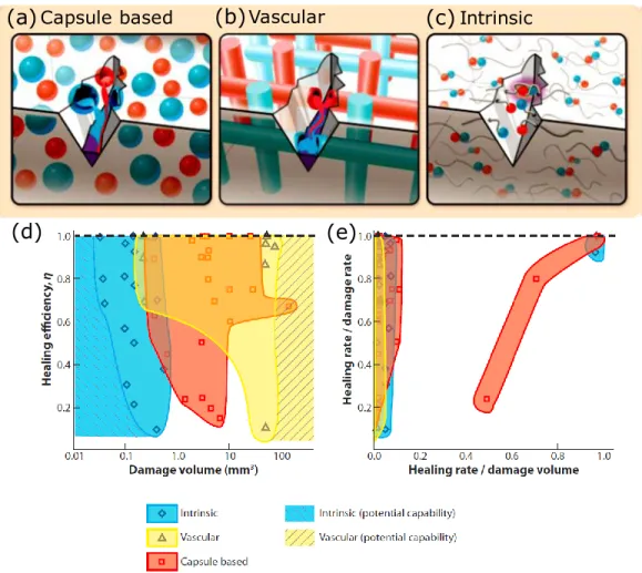
Self-healing materials have attracted great attention due to their ability to heal damage for prolonging the lifetime of materials. The materials involve autonomic or nonautonomic healing, relying on whether an external stimulation (e.g., temperature[75]or light [76, 77]) is needed or not. There are three main methods to produce self-healing materials: capsule-, vascular- and intrinsic-based strategies [78]. The first two methods rely on the release of monomers and a catalyst that are loaded into microcapsules (Figure 2.3(a)) or stored inside vessels (Figure 2.3(b)) to heal the matrix damage. White group in 2001 firstly reported a self-healing system that can spontaneously heal a crack in the material by releasing the microcapsulated healing monomer to polymerize the material [79]. They allow self-healing of large material volume (Figure 2.3(d)). However, these two methods have disadvantages of complicated fabrication processes and a depletion of the local healing agent. Figure 2.3(c) shows intrinsic-based self-healing methods that depend on the molecular interactions in the polymer such as host-guest interactions, hydrogen bonds, electrostatic
interactions and metal-ligand coordination. For example, Miyamae et al. reported a supramolecular hydrogel that can be healed via host–guest interactions under wet conditions [80]. Intrinsic self-healing polymers with relatively fast self-self-healing processes (Figure 2.3(e)) could be achieved by designing the polymer compositions. However, it may be unable to obtain large-volume self-healing (Figure 2.3(d)).
Figure 2.3: Demonstration of self-healing methods including (a) capsule-based, (b) vascular-based and (c) intrinsic-vascular-based approaches. (d) performance maps of different self-healing
materials on the healing of different volumes and healing rate [78].
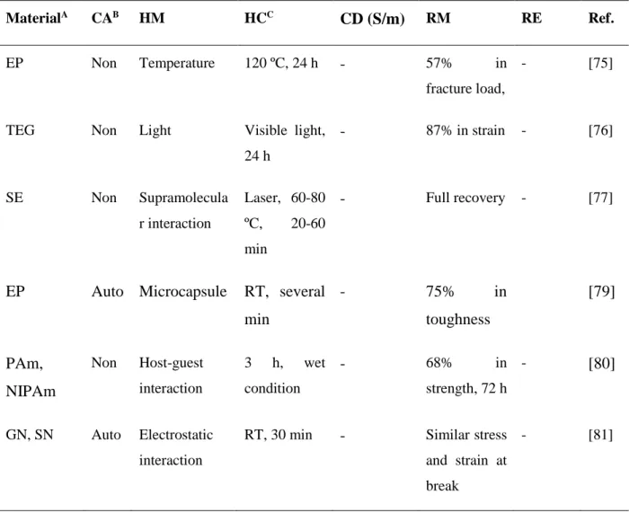
Table 2.3 shows a list of studies on self-healing materials with different classification (CA), healing mechanism (HM), healing condition (HC), conductivity (CD) and recovery of mechanical (RM) and electrical (RE) properties. Intensive research has currently been taken into self-healing materials that are capable of recovering mechanical properties. For example, Diba et al. demonstrated self-healing composite colloidal gels by carefully controlling the assembly of gelatin
(a)Capsule based (b)Vascular (c)Intrinsic
and silica nanoparticles [81]. Zhao et al. demonstrated CS-based hydrogels that can spontaneously heal the damage within 6 h at 25 °C [82]. Despite their great self-healing designs, a lack of electrical conductivity limits their electronic applications. Odom et al. also provided an example of using solvent-filled microcapsules from a conductive silver ink to heal damage, allowing excellent restoration of conductivity [83]. Cao et al. investigated a polar polymer network combined with a ionic salt to obtain a ionic conductor with autonomous self-healing capability by harnessing ion-dipole interactions [84], but a low conductivity of 0.01 S/m was presented. A rGO-based nanocomposite (conductivity of 90 S/m) was developed with autonomic self-healing to restore mechanical and electrical properties. However, the fabrication method (freeze-casting) is difficult to fabricate precisely controlled 3D structures.
Table 2.3: Various examples of self-healing materials
MaterialA CAB HM HCC
CD (S/m) RM RE Ref.
EP Non Temperature 120 ºC, 24 h - 57% in fracture load,
- [75]
TEG Non Light Visible light, 24 h - 87% in strain - [76] SE Non Supramolecula r interaction Laser, 60-80 ºC, 20-60 min - Full recovery - [77]
EP Auto Microcapsule RT, several min - 75% in toughness [79] PAm, NIPAm Non Host-guest interaction 3 h, wet condition - 68% in strength, 72 h - [80] GN, SN Auto Electrostatic interaction
RT, 30 min - Similar stress and strain at break
CEC, OSA Auto Imine bond, acylhydrazone bond 25 ºC, 12 h 90% in strain at break, 12 h - [82]
AgP, PUE Auto Microcapsule RT, 10 min Resistance of 0.95 Ω 80% in voltage [83] PVDF-co-HFP Auto Ion–dipole interaction 5 min 0.01 100% - [84]
PBS/rGO Auto Dynamic dative bond
Several min 90 Complete,
24 h
90% in CD
[85]
Our work Non Electrostatic interaction Water vapor, 5-60 s 1450 90% in toughness 95% in CD
A: EP: epoxy, TEG: tetra(ethylene glycol), SE: supramolecular elastomers,AgP: silver particle, PUE: polyurethane elastomer, PAm: poly(acrylamide), NIPAm: poly(N-isopropylacrylamide), GN:
gelatin nanoparticle, SN: silica nanoparticle, CEC: N-carboxyethyl CS (CEC), OSA: oxidized sodium alginate, PVDF-co-HFP: poly(vinylidene fluoride-co-hexafluoropropylene, PBS: polyborosiloxane, rGO: reduced graphene oxide, B: Auto: autonomic, Non: nonautonomic; C: RT: room temperature.
2.4 Fabrication techniques used for 3D chitosan structures
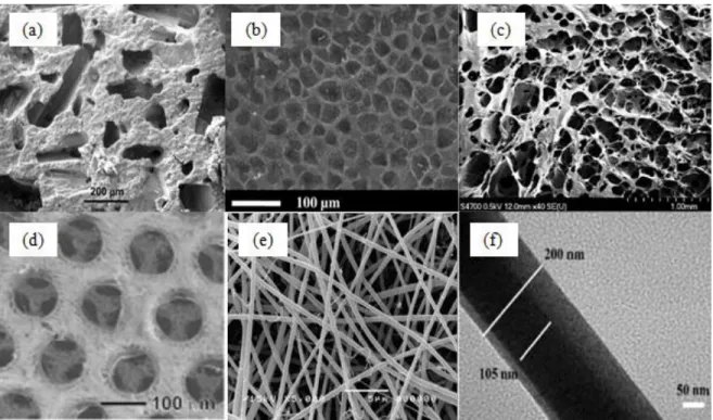
Conventional fabrication techniques, including solvent casting, phase separation, freeze drying, and electrospinning, have been extensively used to produce 3D CS scaffolds.
Figure 2.4: Typical CS constructs fabricated using various scaffolding techniques (a) scanning electron microscope (SEM) image of CS scaffold by solvent-casting. (b) SEM image of CS scaffold produced by gas forming [86]. (c) SEM image of CS scaffold by freeze drying [9]. (d) CS scaffold fabricated by freeze drying [87]. (e) electrospun CS nanofibrous membrane [10]. (f)
core-shell structured PEO-CS nanofibers by coaxial electrospinning [88].
Solvent casting
Solvent casting technique offers an easy and inexpensive way to fabricate scaffolds. Specifically, the polymer/salt composite is cast into a mold and water-soluble porogens, e.g. wax, salts or sugars, are used to create pores or channels [7, 89]. Sponge-like scaffolds are obtained by evaporating the solvent and removing the porogen [7, 8]. Figure 2.4(a) shows the CS-calcium phosphate scaffolds prepared by solvent casting with different macroporosity (i.e., 17.6 %-65.5 %) and pore size of 165 µm to 271µm. The scaffolds strength range from 0.3 to 8 MPa as the macroporosity is decreased [90]. The limitations of CS scaffolds fabricated by this approach are that they may retain some of the toxicity from the solvent and it is difficult to obtain high porosity of scaffolds.
Gas foaming
Gas foaming has the advantages of requiring neither toxic solvents nor high temperature [89]. Compression-molded polymer disks are exposed to carbon dioxide (CO2) gas under high pressure to generate highly porous scaffolds. The solubility of carbon dioxide in the polymer declines as pressure is released, as phase separation occurs between the polymer and carbon dioxide gas, which allows the formation of a porous structure [2]. Figure 2.4(b) shows the CS scaffolds fabricated by using dense gas CO2 and cross-linkers. Highly porous, wet, and rigid structures were obtained and the average pore diameter of the scaffolds was around 40 µm [86]. The CS scaffolds produced by this technique however lead to low pore interconnectivity, especially on the surface of the structure.
Freeze drying
After dissolving in a solvent (acetic acid, water, or benzene), the polymer solution is poured into a mold, frozen and freeze-dried to acquire highly porous scaffolds under high vacuum [8, 89]. Cross-linked CS scaffolds (Figure 2.4(c)) produced for skin regeneration had pore size of roughly 150 µm and porosities from 79% to 85% [9]. The scaffolds achieved maximum tensile strength of 81 kPa; much lower than the ultimate tensile strength (7.7 MPa) of human skin [91]. Despite the advantages of the low temperature maintaining the original properties of scaffolds and not necessarily using toxic solvents, freeze drying has the limitation of obtaining scaffolds with small and inhomogeneous pore size [89]. Choi et al. developed CS scaffolds (Figure 2.4(d)) by using polycaprolactone (PCL) microspheres with freeze drying before removing the PCL with DCM to form uniform pore structures. The final CS scaffolds were formed without using cross-linkers based on pH dependence of CS solubility [87]. However, the process is still time-consuming and complicated.
Electrospinning
procedure involves creating a high intensity electric field between a nozzle and a collector with electric opposite charges [92, 93]. The polymer solution in the nozzle overcomes the liquid surface tension and then is ejected to form fibers which are deposited in the collector [92]. Figure 2.4(e) illustrates two-dimensional (2D) nanofibrous CS membranes produced by electrospinning combined with solvent-cast, with fiber diameters of 126 ± 20 nm and membrane thickness of 72 ± 5µm [10]. CS was mixed with poly(ethylene oxide) for achieving electrospinability in electrospinning [94]. Core-shell constructed CS nanofibers (Figure 2.4(f)) have been fabricated by coaxial electrospinning [88]. The CS scaffolds produced by electrospinning exhibit properties of high porosity, a wide range of pore distribution, and high surface area. However, it is difficult to obtain 3D structures and the obtained 3D scaffolds have the drawbacks of inhomogeneous pore distribution, tortuous pores, and small pore size [95, 96].
2.5 3D printing
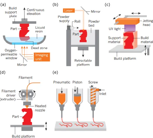
3D printing consists of a computer-controlled translation stage, allowing the fabrication of materials via transforming the digital design into 3D objects. Unlike traditional manufacturing techniques that need molds or lithographic masks to fabricate 3D structures, 3D printing can fabricate complex 3D structures via rapid prototyping. 3D printing has numerous advantages such as low-cost, reliability, mass customization and design flexibility. It can be divided into light-based printing such as stereolithography (SLA), and ink-based printing such as robotic dispensing, as shown in Figure 2.5 [97].
Figure 2.5: 3D printing methods classified into light- and ink-based printing methods. (a) Light-based printing: SLA of liquid resin. (b) Light-Light-based printing: selective laser sintering of polymeric or metallic powders. (c) Light-and ink-based inkjet printing. (d) Ink-based fused
deposition modelling. (d) Robot dispensing using viscoelastic inks [97].
Light-based 3D printing methods use light sources such as laser and photon to form structures, such as SLA and selective laser sintering (SLS). In the fabrication process of SLA, a liquid resin is continuously photopolymerized by a laser, and the structure is built by the solidification of a new layer resin via the photopolymerization (Figure 2.5(a)). SLA requires the inks with low to moderate viscosity. In SLS, the polymeric powders such as ceramic are locally fused by a laser to form 3D structures in a powder bed (Figure 2.5(b)). Other light-based methods such as two-photo polymerization (2PP), digital projection lithography (DLP) are also used to fabricate various structures.
(a) (b) (c)
Ink-based 3D printing methods can pattern materials by using 3D-printable inks through either droplet- or filament-based 3D printing. Droplet-based printing methods such as inkjet printing, hot-melt printing use low-viscosity soft materials to fabricate structures. Inkjet printing can incorporate light-based printing. For example, some inkjet printers involve an ultraviolet (UV) light source that can photopolymerize a liquid resin during the printing process (Figure 2.5(c)). Filament-based 3D printing employs an applied pressure, mechanical force or heating to extrude materials as a continuous filament. For example, fused deposition modelling (FDM) can fabricate thermoplastic polymers into different structures in a layer-by-layer manner. A heating extrusion head is used to melt the thermoplastic filaments and the filaments solidify as they cool in air (Figure 2.5(d)). An alternative technique to FDM is robotic dispensing (Figure 2.5(e)). For this method, a 3D-printable ink is loaded into a syringe and extruded either by pneumatic, piston- or screw-driven force on a platform. It offers a wide range of ink designs such as fugitive inks [23], collagen [29], poly(dimethyl siloxane) (PDMS) [98], nanocomposites [99, 100], and polylactic acid (PLA) [25]. Solidification of these materials to yield desired structures is either through concentrated inks, supported bath or reservoir, tailoring desired rheological properties (e.g., shear thinning behavior, viscoelastic properties), or solvent evaporation. In some cases, additional processing steps are also performed to solidify the ink during the fabrication process, such as UV-assisted polymerization used to form self-supporting and freeform structures [101] and low-temperature (−20 °C) applied to solidify the ink filament on a cryogenic plate [102].
2.6 3D printing of natural polymers
Biomaterials commonly used for 3D printing are ceramics, metals (e.g., using SLS based on polymeric or metallic powders) and synthetic polymers such as PLA (e.g., using FDM based on thermoplastic polymers) and photosensitive polymers (e.g., SLA based on photopolymerizable resins), and metals. However, these 3D printing have limitations to fabricate very soft materials
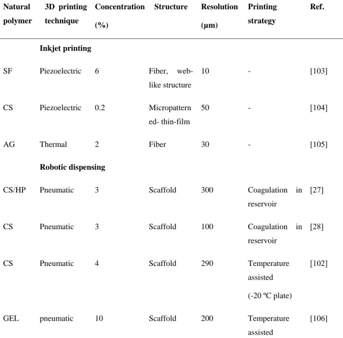
such as naturally derived hydrogels. Natural polymers including polysaccharides and proteins still remains challenging to 3D print, since they are too soft to support themselves and thus may collapse or deform during the printing process [29]. Current approaches for 3D printing of natural polymers have obtained significant advances. Table 2.4 shows a collection of natural polymers that can be fabricated by 3D printing. Inkjet printing and robotic dispensing are normally used to generate various structures using natural polymers.
Table 2.4: Summary of natural polymers fabricated by 3D printing Natural polymer 3D printing technique Concentration (%) Structure Resolution (µm) Printing strategy Ref. Inkjet printing
SF Piezoelectric 6 Fiber, web-like structure 10 - [103] CS Piezoelectric 0.2 Micropattern ed- thin-film 50 - [104] AG Thermal 2 Fiber 30 - [105] Robotic dispensing
CS/HP Pneumatic 3 Scaffold 300 Coagulation in reservoir
[27]
CS Pneumatic 3 Scaffold 100 Coagulation in reservoir
[28]
CS Pneumatic 4 Scaffold 290 Temperature assisted
(-20 ºC plate)
[102]
GEL pneumatic 10 Scaffold 200 Temperature assisted
(10 ºC plate)
GEL Pneumatic 5 Scaffold 350 Adding
crosslinker to tailor ink rheology
[107]
CNC Pneumatic 20 Scaffold 410 Concentrated ink
[108]
SF Pneumatic 28–30 Scaffold 5 Concentrated ink [24] SF - 10-16 Hierarchical scaffold > 500 Adding sacrificial organic microparticles [109] SF Piston 10 Complex structures 200 Thermoreversibl e support bath [29]
HA Piston 5-20 wt Scaffold 100 UV assisted [110]
AG, CAI Piston 4, 10, 8.94-9.64 Complex biological structures 200 Thermoreversibl e support bath [29] Our work Pneumatic 8 Scaffold, complex structures 30 Directly printing in air [111]
SF: silk fibroin, AG: alginate, HP: hydroxyapatite, CNC: cellulose nanocrystals, Ad–HA and CD– HA: HA modified with either adamantane (Ad) or β-cyclodextrin (β-CD), HA: hyaluronic acid, CAI: collagentype I
2.6.1 Inkjet printing
be divided into thermal and piezoelectric inkjet printing [112]. Thin structures of silk fibroin (SF), chitosan (CS) and alginate (AG) were produced by inkjet printing (Table 2.4). For example, CS micro-pattern (Figure 2.6(a)) was generated on glass by inkjet printing to enhance cell mobility, spreading, and phagocytosis [104]. However, the process always used an ink with low viscosity [113] and was difficult to obtain a 3D structure with high aspect ratio (i.e., vertical direction).
Figure 2.6: CS scaffolds fabricated by 3D printing. (a) CS micropattern generated by inkjet printing [104]. (b) CS scaffold fabricated by robotic dispensing [27]. (c) CS scaffold by robotic
dispensing [28]. (d) CS scaffold fabricated by cryogenic 3D plotting system [102].
2.6.2 Robotic dispensing
Rather than single droplet, robotic dispensing can continuously extrude fibers and offers more direct control of the flow of the ink [114]. The fabrication process of natural polymers usually involved in situ gelling during the printing process to support the structure by using a bath or reservoir (Table 2.4) [27-29]. Out of this strategy, temperature- or UV-assisted step was applied to solidify the structures during the printing process [102, 106, 110]. Also, concentrated inks were
normally used to avoid the shape deformation due to drying-induced shrinkage [24, 108]. There are
a few cases of 3D printing CS, either using a reservoir to conjugate the ink or using a temperature-assisted step during the printing process. Figure 2.6(b) shows 3D CS scaffolds fabricated by a CS solution (3% w/v) deposited into a bath with a mixture of NaOH-ethanol solution [27]. The scaffold had a fully interconnected channel structure with a maximum of 21 layers and the surface of scaffolds was rough. Macrospore diameters were observed from 400 to 1000 µm [27]. Figure 2.6(c) illustrates CS scaffolds produced by dispensing CS and NaOH at the same time. Four-layered scaffolds with pore diameters of 200-500 µm were produced by using nozzles with diameters of 100 and 200 μm. Both of the methods use the pH dependence of CS solubility. Lee et al. fabricated CS scaffolds by robotic deposition with a cryogenic refrigeration system. CS solution was solidified to form a structure on a temperature controlled plate (-20 ℃) and the final porous scaffolds were generated by post-treatment of freeze-drying and cross-linking [102]. Figure 2.6(d) shows a CS scaffold exhibiting homogeneous pore size and high interconnectivity as well as rough surface. The filament diameters of CS scaffolds ranged from 290 to 310 μm and the pore sizes was around 400 μm. The CS scaffolds with dimensions of 10 ×18 ×1.8 mm3 had a maximum tensile strength of 0.16 MPa and maximum Young’s modulus of 1.2 MPa [102].
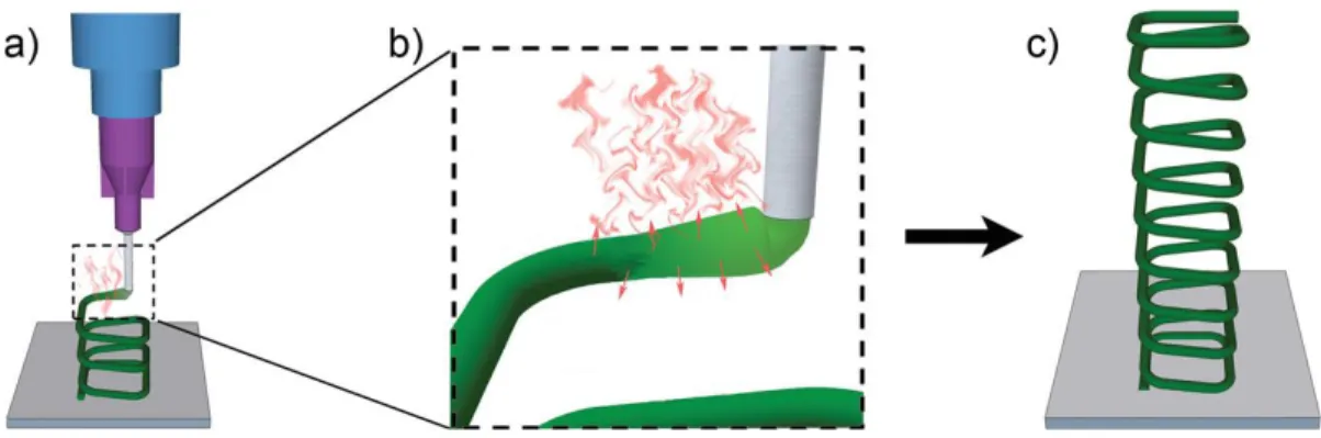
2.6.2.1 Solvent-cast 3D printing
Solvent-cast 3D printing is typically based on a robotic dispensing system. Solvent-cast 3D printing can produce 3D structures at room temperature including a syringe inserted the ink and the ink is extruded on a plate to create filament, combined with rapid solvent evaporation (Figure 2.7) [25].
![Figure 2.1: Structures of CS and chitin. a) CS, b) chitin [36].](https://thumb-eu.123doks.com/thumbv2/123doknet/2352014.36491/24.918.153.805.576.730/figure-structures-cs-chitin-cs-b-chitin.webp)
![Table 2.2: Physical properties of different carbon materials [74]](https://thumb-eu.123doks.com/thumbv2/123doknet/2352014.36491/31.918.112.800.148.612/table-physical-properties-different-carbon-materials.webp)
![Figure 2.6: CS scaffolds fabricated by 3D printing. (a) CS micropattern generated by inkjet printing [104]](https://thumb-eu.123doks.com/thumbv2/123doknet/2352014.36491/42.918.225.692.310.685/figure-scaffolds-fabricated-printing-micropattern-generated-inkjet-printing.webp)
![Figure 2.8: 3D nanocomposite macro- and micro-structures fabricated using different 3D printing methods [20].](https://thumb-eu.123doks.com/thumbv2/123doknet/2352014.36491/45.918.156.763.100.612/figure-nanocomposite-macro-structures-fabricated-different-printing-methods.webp)