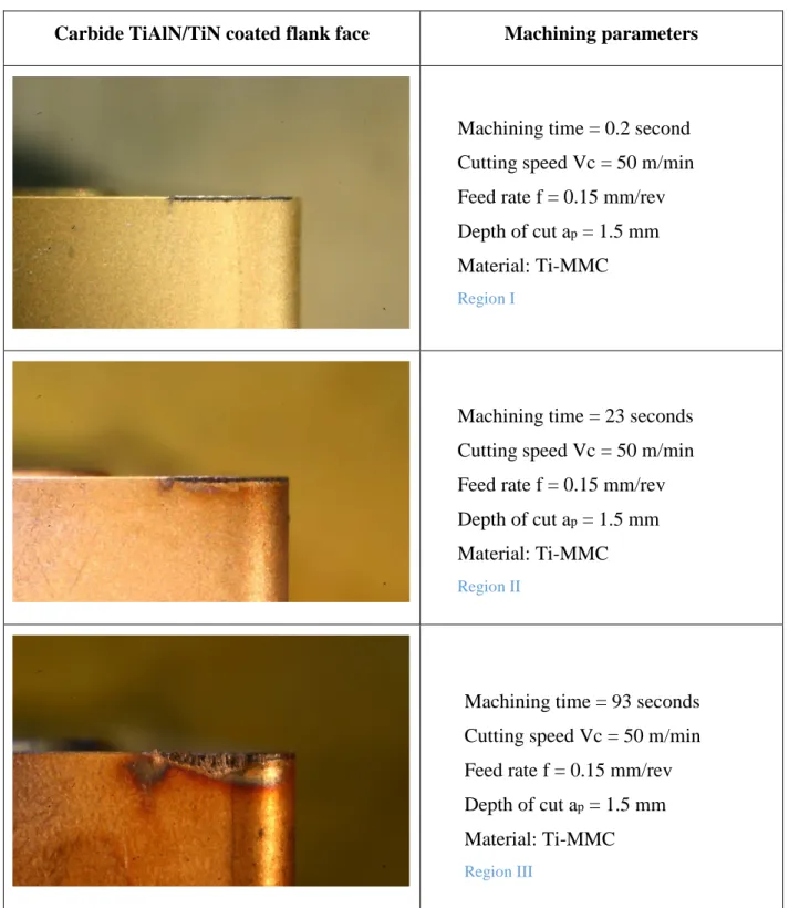
Initial Tool Wear Mechanisms in Turning of Titanium Metal Matrix Composites
Texte intégral
Figure
Documents relatifs
ARTICLE 4: ESTIMATING THE REMAINING USEFUL TOOL LIFE OF WORN Chapter 5 TOOLS UNDER DIFFERENT CUTTING CONDITIONS: A SURVIVAL LIFE ANALYSIS DURING TURNING OF TITANIUM
The fractal dimension, other fractal parameters based on regularization analysis of the total cutting force signal during titanium machining were calculated to
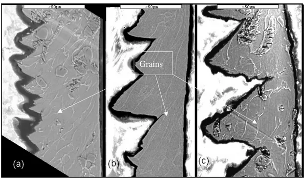
Through SEM observations and chemical analysis of the tested inserts, it is shown that the dominant wear mechanisms are adhesion and diffusion due to chemical affinity
(2008) analysed the influence of tool geometry (tool cutting edge preparation), cutting speed, uncut chip thickness and tool wear on residual stress distribution in the
This study highlights the impact of high-pressure water jet assistance on tool life for the machining of the Ti17 titanium alloy, for both finishing and roughing conditions.. It is
Yessine AYED, Guénaël GERMAIN, Amine AMMAR, Benoit FURET - Tool wear analysis and improvement of cutting conditions using the high-pressure water-jet assistance when machining the
This study highlights the impact of high-pressure water jet assistance on tool life for the machining of the Ti17 titanium alloy, for both finishing and roughing conditions. It is
Tool wear analysis and improvement of cutting conditions using the high-pressure water-jet assistance when machining the Ti17 titanium alloy... For this purpose, the influence of
