Open Archive TOULOUSE Archive Ouverte (OATAO)
OATAO is an open access repository that collects the work of Toulouse researchers and
makes it freely available over the web where possible.
This is an author-deposited version published in :
http://oatao.univ-toulouse.fr/
Eprints ID : 16721
To link to this article : DOI : 10.1016/j.actamat.2016.03.054
URL :
http://dx.doi.org/10.1016/j.actamat.2016.03.054
To cite this version : Amin-Ahmadi, Behnam and Connétable,
Damien and Fivel, Marc and Tanguy, Döme and Delmelle, Renaud
and Turner, Stuart and Malet, Loic and Godet, Stephane and
Pardoen, Thomas and Proost, Joris and Schryvers, Dominique and
Idrissi, Hosni Dislocation/hydrogen interaction mechanisms in
hydrided nanocrystalline palladium films. (2016) Acta Materialia,
vol. 111. pp. 253-261. ISSN 1359-6454
Any correspondence concerning this service should be sent to the repository
administrator:
[email protected]
Dislocation/hydrogen interaction mechanisms in hydrided
nanocrystalline palladium films
Behnam Amin-Ahmadi
a, Damien Conn!etable
b, Marc Fivel
c, D€ome Tanguy
d,
Renaud Delmelle
e, Stuart Turner
a, Loic Malet
f, Stephane Godet
f, Thomas Pardoen
e,
Joris Proost
e, Dominique Schryvers
a, Hosni Idrissi
a,e,*aElectron Microscopy for Materials Science (EMAT), Department of Physics, University of Antwerp, Groenenborgerlaan 171, B-2020 Antwerp, Belgium bCIRIMAT, CNRS-INP-UPS UMR 5085, Ecole Nationale d’Ing!enieurs en Arts Chimiques et Technologiques (ENSIACET) 4, all!ee Emile Monso, BP 44362,
F-31030 Toulouse Cedex 4, France
cSIMaP-GPM2, Universit!e Grenoble Alpes-CNRS, F-38000 Grenoble, France d
Institut Lumi#ere Mati#ere, UMR5306 Universit!e Lyon 1-CNRS, Universit!e de Lyon 69622 Villeurbanne Cedex, France
eInstitute of Mechanics, Materials and Civil Engineering, Universit!e catholique de Louvain, Place Sainte Barbe 2, B-1348 Louvain-la-Neuve, Belgium fUniversit!e Libre de Bruxelles, Matters and Materials Department, 50 Av. FD Roosevelt CP194/03, 1050 Brussels, Belgium
Keywords: Palladium Dislocation Hydrogen Ab-initio calculations Thin films
a b s t r a c t
The nanoscale plasticity mechanisms activated during hydriding cycles in sputtered nanocrystalline Pd films have been investigated ex-situ using advanced transmission electron microscopy techniques. The internal stress developing within the films during hydriding has been monitored in-situ. Results showed that in Pd films hydrided tob-phase, local plasticity was mainly controlled by dislocation activity in spite of the small grain size. Changes of the grain size distribution and the crystallographic texture have not been observed. In contrast, significant microstructural changes were not observed in Pd films hydrided to a-phase. Moreover, the effect of hydrogen loading on the nature and density of dislocations has been investigated using aberration-corrected TEM. Surprisingly, a high density of shear type stacking faults has been observed after dehydriding, indicating a significant effect of hydrogen on the nucleation energy barriers of Shockley partial dislocations. Ab-initio calculations of the effect of hydrogen on the intrinsic stable and unstable stacking fault energies of palladium confirm the experimental observations.
1. Introduction
Owing to its fast and reversible hydriding kinetics, palladium (Pd) is an ideal model system to study hydrogen purification and sensing applications. This is essential for hydrogen energy tech-nology, one of the cleanest alternative to fossil fuels[1,2]. Pd has a high sensitivity and selectivity with respect to hydrogen and can release hydrogen at room temperature[2].
Recently, nanocrystalline (nc) Pd thin films have been widely used in hydrogen applications because of large surface and sub-surface site densities and of the presence of a high fraction of grain boundaries (GBs) which can facilitate the hydriding process[2,3].
These layers must be thin enough to ensure high hydrogen permeability while remaining mechanically stable [4]. The crys-talline structure of Pd is a face centered cubic (fcc) lattice, also referred to as the
a
-phase, in which interstitial hydrogen atoms occupy part of the octahedral sites. During hydriding, as long as the H/Pd ratio stays belowa
SSmaxz 0.02 (atomic ratio) at room tem-perature, the fcca
-Pd lattice parameter can expand from 3.889 Å to 3.895 Å. When H/Pd ratio reaches 0.02 a so-calledb
-phase appears with a lattice constant near 4.025 Å, and again an fcc structure. The two phases coexist up to a ratio H/Pdb
SSminz 0.58 at which thea
-phase entirely disappears. The initial volume of the Pd structure expands by about 10% when the H/Pd ratio reaches about 0.5. This dilatation can generate extremely large overall compressive stresses if the deformation is impeded by a mechanical constraint imposed to the material, such as in the case of a film lying on a thick substrate. If the material is unconstrained, it can still undergo large local stress variation if the transformation does not take place homogenously. The large local or overall stress can induce severe local or global plastic deformation, respectively[2e8]. It was first*Corresponding author Electron Microscopy for Materials Science (EMAT), Department of Physics, University of Antwerp, Groenenborgerlaan 171, B-2020 Antwerp, Belgium; Institute of Mechanics, Materials and Civil Engineering, Uni-versit!e catholique de Louvain, Place Sainte Barbe 2, B-1348 Louvain-la-Neuve, Belgium.
E-mail address:[email protected](H. Idrissi).
shown by Wise et al.[9]that coarse-grained Pd after being sub-jected to a hydriding/dehydriding cycle contains a large dislocation density which is comparable with the dislocation density of a heavy cold-worked Pd[9,10]. Flanagan et al.[11]also reported that plastic deformation occurs both during hydriding and dehydriding in Pd which leads to an increase of the dislocation density. It has also been shown by transmission electron microscopy (TEM) results that after cold-working Pd, dislocations are arranged in cell walls with only a few dislocations within the cells, but when dislocations are created by a hydriding/dehydriding cycle, they are distributed more uniformly and it is difficult to discern a cell structure[9,12].
Robertson et al. also intensively investigated the mechanisms of hydrogen-dislocation interactions using environmental TEM for stainless steel[13], Ti[14,15]and pure Al[16]. They reported that hydrogen decreases the stacking fault energy in 310s stainless steel (SFE) and enhances the dislocation mobility (the movement of dislocations occurred at a lower applied stress). They interpreted these results by a shielding of the elastic interactions between defects (dislocationedislocation and dislocation-pinning points). They have also investigated the separation distance between dis-locations in a pileup during H absorption/desorption in pure Al. The results showed the reversible movement of dislocations in a pileup after an absorption/desorption cycle, coherent with elastic shield-ing in the absence of solute pinnshield-ing effects in high purity Al. Several other experimental studies have been dedicated to the study of the effect of hydrogen on the microstructure and mechanical proper-ties of bulk coarse-grained Pd such as the evolution of dislocation density and hardness after hydriding[17e21]. The nanoindentation
experiments on coarse-grained Pd showed that local hardness is increased by 50% after hydriding the Pd to
b
-phase[19]. However, in depth experimental investigations on the elementary plasticity mechanisms activated in nc Pd films under hydrogen loading are still missing in the literature. Because of the complexity of the microstructure of nc metals, the microstructural changes associated to the effect of hydrogen loading may strongly differ from coarse-grained metals. Indeed, in nc metals, depending on the grain size and the local stress, the nucleation of leading partial dislocations from GBs and twinning can be favored over the formation of full lattice dislocations even in high SFE metals[22]. Furthermore, GB processes such as grain growth and grain rotation can be activated due to the increase of the local or overall stress during hydriding[23]. Another unexplored aspect concerns the experimental investigation of the nanoscale mechanisms controlling the dislo-cation/hydrogen interactions in Pd. Only a few investigations based on numerical simulations have recently tackled these questions but on other metallic materials such as nickel (Ni), aluminum (Al) and
a
-iron (Fe)[24e26]. Lu et al.[27]performed ab-initio calculationsand found that both unstable and stable SFE in Al decrease by 50% when hydrogen atoms occupy the octahedral sites of fcc Al. Simi-larly, Taketomi et al.[28]showed through molecular statics simu-lations that the stable SFE decreases with increasing hydrogen concentration in
a
-Fe. Wen et al.[29]also investigated the effect of hydrogen on the dissociation of screw dislocations in Ni using the embedded-atom method, and showed that the stacking fault width of screw dislocations increases with increasing hydrogen concen-tration. Tang et al.[25]reported that the increase of the hydrogen concentration in Ni decreases the stable SFE due to the resulting negative binding energy of hydrogen to the SF, while the unstable SFE increases with increasing hydrogen concentration.However, direct experimental evidences on the effect of hydrogen on the nucleation energy barriers of partial dislocations in fcc metals are still absent in the literature.
Finally, there is no doubt that the accumulation of irreversible microstructural changes during hydriding cycles on nc Pd films can alter the mechanical properties of these films (i.e., ductility,
hardening, creep, etc). Defects generated in hydrided nc Pd used in sensing applications can also have other effects such as shortening of a sensing cell's lifetime, interruption of the electrical circuitry and lowering of the device's sensing sensitivity and proficiency [30]. Therefore, it is of primary importance to uncover the elementary plasticity mechanisms activated during hydriding of nc Pd thin films. In the present study, we have performed detailed TEM charac-terizations on nc Pd thin films prepared using sputter deposition and hydrided at low and high pressures for
a
-phase andb
-phase transformation, respectively. The internal stress developing within the films during hydriding has been monitored in-situ using an original experimental setup based on the measurement of the curvature of the Pd films during hydriding[2,31]. Statistical ana-lyses of the grain size/morphology as well as the crystallographic texture have been performed using automated crystal orientation mapping in TEM (ACOM-TEM) while aberration corrected high resolution TEM (HRTEM) has been used to unravel the nature and the near-core properties of the defects generated during hydriding. The results revealed strong interaction of hydrogen with extended defects as well as a clear effect of hydrogen on the nucleation en-ergy barriers of Shockley partial dislocations of Pd which was confirmed using ab-initio calculations. The results also provide insightful information for the validation of atomistic simulations on the interaction of hydrogen with extended defects and for better understanding of the effect of hydriding on the macroscopic me-chanical properties of nc metallic thin films.2. Materials and methods
In the present study, 150 nm thick Pd films were sputter-deposited at room temperature with a deposition rate of 0.3 nm s!1under an argon (Ar) plasma pressure of 1.07 Pa. Hydriding cycles were performed after pumping down a vacuum chamber to base pressures better than 10!6mbar, followed by the introduction of ultra-pure Ar/H2gas mixtures to instantaneously impose a desired partial pressure. The hydriding cycles were performed at partial pressure of pH2¼ 2.26 mbar for
a
-phase and 97.5 mbar forb
-phaseformation. The gas mixture was then pumped out of the chamber, resulting in a gradual decrease of the internal stress within the films due to reversible dehydriding at room temperature. A high-resolution curvature measurement setup is mounted onto the hydriding chamber and continuously detects the positions of mul-tiple laser beams reflecting off a cantilevered sample, hence moni-toring the sample curvature in real time[31]. The change in internal stress in the Pd layer, which is the result of the restricted in-plane expansion during PdeH interaction in the film-on-substrate geom-etry, can be derived from the measured changes in curvature[2,32]. After dehydriding, the system returns to ambient conditions, i.e. room temperature and atmospheric pressure. The hydrogen is released from the film and cross-sectional and plan-view TEM thin foils were prepared using Focused Ion Beam (FIB) thinning with the “lift-out” procedure. Conventional and HRTEM characterizations of the Pd films before and after hydriding were carried out using a FEI Tecnai G2 (FEG, 200 kV). A FEI Titan 80e30000cubed” microscope with aberration correctors for imaging and probe was used to reveal the near-core properties of defects induced by the hydriding. Spatially resolved electron energy loss spectroscopy (EELS) tech-nique was also used to detect the residual hydrogen on the core of dislocations after hydriding.
The dislocation density was measured by counting extra half planes in HRTEM images. For better visualization of the extra half planes, a mask was applied on each g-vector and the corresponding Inverse Fast Fourier Transform (IFFT) was generated showing one family of planes. This procedure was used for all main spots present in the FFT pattern. Thus, the dislocation density was calculated
based on the number of extra half planes presented in all IFFT images. Special precaution was taken to exclude regions exhibiting the so-called “reversal of contrast” due to changes of thickness/ defocus. A series of HRTEM images from a given region were thus obtained at different defocus in order to reveal the presence of contrast reversal. Also, special attention was paid to avoid the misidentification of Moir!e-effect-induced lattice image shifting as dislocations. In order to allow easy visualization of single disloca-tions, local g-maps were also obtained using Geometric Phase Analysis (GPA) which is an image processing technique sensitive to small displacements of the lattice fringes in HRTEM images[33]. A mask is applied in the FFT of the HRTEM image and centered on the periodicity (g-vector) of interest.
Twin boundary (TB) density was also measured using bright field (BF) and dark field (DF) micrographs. Around 60 grains for each film were included in the analysis. In order to ensure no twins were missed the sample was tilted up to ±30$along two perpen-dicular directions. Subsequently, BF images were taken after each 1$tilting.
The grain size distribution as well as the crystallographic texture of the Pd films were investigated by the ACOM-TEM technique using a Philips CM20 equipped with a LaB6gun at 200 kV. This technique which uses small probe diffraction spot patterns in TEM is an effective method for mapping phase and crystal orientation and an alternative to Orientation Imaging Microscopy using Elec-tron Backscattered Diffraction for scanning elecElec-tron microscopes based on Kikuchi lines. A selected area is scanned with a small probe and the electron diffraction spot patterns are collected using an external Charge-Coupled Device camera. Off-line, every diffraction pattern is compared to the pre-calculated templates of selected phases and the best match is selected. In order to eliminate the ambiguity that can exist for highly symmetric orientations, a build in clean-up procedure in the OIM TSL®
software from EDAX Inc. has been used. Owing to this clean-up procedure a single orientation for each ambiguous situation can be selected.
First-principles calculations were also performed using VASP (Vienna ab initio simulation package)[34]to measure the gener-alized planar fault energies (GPFEs) of PdeH system. To describe the electroneion interactions, the projector augmented-wave (PAW) method [35] was used. The wave functions on a plane wave basis with a maximum kinetic energy of 400 eV was also expanded. The exchange-correlation functional within the generalized gradient approximation (GGA) is based on the parametrization provided by Perdew, Wang and Ernzerhof (PBE)
[36]. The magnetic moment was not taken into account in this work, as Pd-fcc and hydride PdH (NaCl-type structure) are not magnetic. To study bulk properties, 3 % 3 % 3 supercells were used. To compute the generalized SFEs, a supercell approach with a free surface along the [111] direction was employed. The slab is composed of 12 atomic layers along the z axis ([111] direction) and 1 or 4 atoms per layer, according to the hydrogen content. The slip was done between the sixth and the seventh layer. The surfaces are separated by a vacuum large enough, equivalent to eight inter-atomic layers, to reduce interactions between dangling bounds of the surfaces. 20 % 20 % 1 Monkhorst-Pack mesh grids[37]were then used to sample the Brillouin zone. These criteria were necessary to reach accurate values (For further details, see
supplementary materials). 3. Experimental results
3.1. TEM characterizations of as-deposited nc Pd films
The ACOM-TEM technique was performed on as-deposited nc Pd film in order to measure the grain size distribution and the
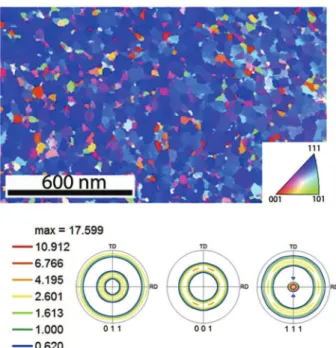
crystallographic texture. Fig. 1 shows the ACOM-TEM results including orientation map and crystallographic texture analysis along <100>, <110> and <111> directions which were performed on plan-view FIB sample of as-deposited Pd film. It is worth noting that the presence of more than one grain across the thickness of the TEM thin foils can affect the automated indexation of the diffraction patterns leading to severe uncertainties on the ACOM-TEM results. In the present work, the plan-view foils have been thinned using FIB to ensure that only one grain is confined through the thickness. Furthermore, in order to avoid ambiguities for the analysis of the grain size distribution, P3 TBs have been excluded in the ACOM-TEM measurements. The results of Fig. 1show that the average lateral grain size in as-deposited Pd film is 61 ± 20 nm. Moreover, the analysis of the crystallographic texture in the as-deposited films reveals a sharp {111} fiber texture normal to the film surface (Fig. 1) which corresponds to the minimum surface energy of fcc metallic films.
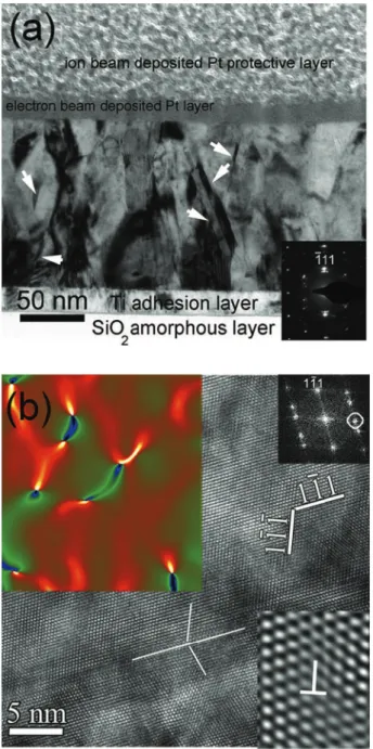
Fig. 2(a) exhibits a BF-TEM micrograph obtained on cross-sectional FIB thin foils in as-deposited nc Pd film. The ring shaped selected area diffraction pattern (SADP) shown as inset inFig. 2(a) reveals the expected fcc Pd crystalline structure. In this figure, a columnar morphological texture with an average elongated aspect ratio (height/lateral dimension ratio) of 3 can be observed. More-over, growth nanotwins are observed within the grains. Some of these twins are indicated by white arrows in the BF micrograph of
Fig. 2(a).Fig. 2(b) shows a HRTEM image of a growth P3{111} coherent TB (CTB). The local g-map shown in the upper left inset (same region in original image) reveals a few lattice dislocations in the matrix. The lower right IFFT inset in the same figure reveals one full lattice dislocation. Dissocitaed dislocations with SFs within the nanograins have not been observed, which is the expected conse-quence of the high SFE of Pd. Indeed, it has been reported in the literature that the SFE of Pd is ranging between 130 and 180 mJ/m2
[38]. The presence of the few full lattice dislocations in the as-deposited films can be explained by the internal stress building up during the deposition of the films[39,40].
Fig. 1. Orientation mapping and corresponding crystallographic texture along <100>, <110> and <111> directions on plan-view as deposited Pd film.
3.2. Internal stress evolution during hydriding of nc Pd films
In the present work, the internal stress has been monitored in-situ during hydriding based on the measurement of the curvature of the Pd films/Si substrate bilayer (see experimental section for more details).Fig. 3shows the evolution of the internal stress as a function of time during a complete hydriding cycle of Pd films at
pH2 ¼ 2.28 and 97.5 mbar which correspond to
a
- andb
-phasetransformations, respectively. The internal tensile stress in the as-deposited Pd films is ~450 MPa. After inserting a gas mixture of Ar/(H21%), the internal stress increases rapidly in the compressive direction, and gradually reaches a constant value of 120 MPa tensile stress for the
a
-phase transformation (curve 1 in Fig. 3) and920 MPa compressive stress for the
b
-phase transformation (curve 2 inFig. 3). This leads to an absolute change of stress of 330 MPa and 1370 MPa, for Pd films hydrided toa
- andb
-phase, respectively. The gas mixture was then pumped out of the chamber after 225s and 380s for Pd films hydrided toa
- andb
-phase, respectively, resulting in a gradual decrease of the internal stress due to reversible dehydriding at room temperature. The role of the increase of the internal stress hydriding on the microstructural changes of the Pd films will be discussed in the following sections. Finally, TEM specimens are prepared ex-situ using FIB.3.3. Effect of hydriding on grain size and crystallographic texture
The ACOM-TEM technique was also performed on Pd film after
Fig. 2. As-deposited Pd film: (a) BF micrograph of cross-sectional FIB specimen. Growth twins are indicated by white arrows. Corresponding SADP is shown in bottom-right inset. (b) HRTEM micrograph of cross-sectional specimen showing P3{111} CTB. The local g-map shown in the upper left inset was obtained from the region covered by the map. The map was obtained using g ¼ 111 indicated by a white circle on the FFT in the upper right inset of (b).
Fig. 3. Evolution of the internal stress in nc Pd thin films as a function of time during hydriding cycles recorded at pH2 ¼ 2.28 and 97.5 mbar to inducea- andb-phase
transformation, respectively.
Fig. 4. Orientation mapping and crystallographic texture along <100>, <110> and <111> directions on plan-view FIB samples prepared on Pd film after hydriding tob -phase.
hydriding in order to investigate the effect of hydrogen loading on the grain size distribution and the crystallographic texture.Fig. 4
shows the ACOM-TEM results including orientation map and crystallographic texture analysis along <100>, <110> and <111> directions which were performed on plan-view Pd films after hydriding to
b
-phase. The results show that the average lateral grain size in Pd film after hydriding tob
-phase slightly increases to 72 ± 20 nm in comparison with the as-deposited sample (61 ± 20 nm, seeFig. 1). However, because such increase falls within the uncertainties of the measurements, the activation of grain growth under hydrogen loading cannot be confirmed. On the other hand, the investigation of the mean grain size after hydriding toa
-phase did not show significant changes (i.e., 60 ± 5 nm).The analysis of the crystallographic texture after hydriding to
b
-phase shows a sharp {111} fiber texture normal to the film surface (Fig. 4) very similar to the as-deposited Pd film. Moreover, the texture intensities along <100>, <110> and <111> directions remain remarkably constant after hydriding tob
-phase. As ex-pected, similar results were obtained in Pd films hydrided toa
-phase.3.4. HRTEM investigation of the nc Pd films after hydriding
Fig. 5(a) shows a <110> HRTEM image in a Pd film after hydriding to
a
-phase. In the upper right inset of this figure, the IFFT of g ¼ 002 taken from the region indicated by dashed lines shows one full lattice dislocation. Note that local dissociation of the dislocation core cannot be resolved similarly to dislocations observed in the as-deposited films (Fig. 2(b)). Intrinsic or extrinsic SFs have not been observed in Pd films after hydriding toa
-phase. The local g-map shown in the bottom left inset (taken from the whole image ofFig. 5(a)) reveals a few lattice dislocations in the matrix similar to the as-deposited sample. The comparison of TB density of as-deposited (9300 ± 600m
m!3) and after hydriding toa
-phase (9460 ± 600m
m!3) shows that twinning mechanism was not activated in Pd films after hydriding toa
-phase.Fig. 5(b) shows a HRTEM image of a growth P3{111} CTB in Pd film after hydriding toa
-phase. The corresponding FFT shows a typical twin relation-ship for CTBs in the fcc structure. It can be seen inFig. 5(b) that, except for a few atomic steps due to the presence of a/6 <112> twinning dislocations (TDs), the TB is almost coherent and atomi-cally sharp. This indicates that growth TBs did not undergo signif-icant interactions with lattice dislocations which can induce strong distortions at the TBs (i.e, loss of the coherency of the TBs)[7,41].These results can be explained by the low amount of hydrogen incorporated in the Pd films during hydriding to
a
-phase leading to very limited hydrogen/defect interactions as well as the small variation of the internal stress during hydriding toa
-phase (curve 1 inFig. 3).Fig. 6(a) shows a HRTEM image obtained along the <110> zone axis in a Pd film after hydriding to
b
-phase. In this figure, it can be seen that the dislocation density has significantly increased after hydriding compared to the as-deposited films (Fig. 2). Indeed, strong local variations of contrast due to the presence of a high density of dislocations are observed in these samples. This is confirmed in the local g-map of the left inset inFig. 6(a). Further-more, in contrast with CTBs observed in the as-deposited films (Fig. 2), the P3{111} CTBs inFig. 6(a) have lost their coherency after hydriding tob
-phase. This loss of coherency is due to the interac-tion of a high density of lattice dislocainterac-tions with P3{111} CTBs inducing different types of structural irregularities such as residual sessile dislocations at the CTBs or lattice dislocations tangling in front of these boundaries[41,42].Dislocation densities have also been quantified in HRTEM im-ages obtained in as-deposited Pd as well as films hydrided to
a
- andb
-phase as shown in Fig. 6(b). The error bars on the individual measurements were obtained by enlarging or shrinking the selected region in a single HRTEM image as long as the number of dislocations does not change, while those on the averages are standard error bars. Note that the scatter of dislocation density is caused by the local nature of individual nc grains of HRTEM images, presented as individual measures (open circles). The measured average lattice dislocation density in as-sputtered Pd film equals 6.0 ± 0.6 % 1016/m2. A slight increase to 6.7 ± 0.9 % 1016/m2has been observed in Pd film hydrided toa
-phase (Fig. 6(b)). However, the measured lattice dislocation density in Pd film hydrided tob
-phase reached 1.25 ± 0.2 % 1017/m2which is almost 2 times higher than the initial density in as-deposited films in agreement with the clear loss of coherency of P3{111} CTBs shown inFig. 6(a). Recently, using X-Ray diffraction and Hydrogen diffusivities, Deutges et al. have reported dislocation densities ranging from 2 % 1014m!2to 14 % 1014 m!2 in coarse-grained bulk Pd samples subjected to hydrogen loading followed by cold-rolling[43]. The difference be-tween these values and those reported in the present work can arise from the difference of the initial microstructure of the Pd samples originating from different processing methods.Fig. 7reveals the effects of hydriding into the
b
-phase regime on the local structure of lattice dislocations within the nanograins.Fig. 5. (a) <110> HRTEM micrograph of a nanograin in Pd film after hydriding toa-phase showing a full lattice dislocation. The IFFT of g ¼ 002 from the region indicated by dashed lines is presented in the upper right inset showing the compact core of the dislocation. The local g-map (g ¼ 002) ofFig. 5(a) is also presented in the lower left inset showing the dislocations as hot spots. (b) <110> HRTEM micrograph of P3{111} CTB in the Pd film hydrated toa-phase showing the existence of a few steps along the TB.
Fig. 7(a) shows a P3{112} Incoherent TB (ITB) connected to a P3 {111} CTB. In this figure, several SFs are indicated by white arrow-heads. The enlarged and IFFT filtered HRTEM image shown in the bottom left inset ofFig. 7(a) shows the shift of the position of the {111} planes due to the presence of one SF. The enlarged IFFTs of the HRTEM images of Figs. 7(b) and 6(c) show details on two SFs located in the grain interior.Fig. 7(b) exhibits an intrinsic SF orig-inating from the dissociation of a full lattice dislocation. Indeed, the Burgers circuits drawn around the partials in the same figure show 30$ and 90$Shockley partial dislocations (SPDs) of type b ¼ a/6 [112] and b ¼ a/6 ½211', respectively. These partials originate from the dissociation of a 60$mixed dislocation following the reaction: 1/2[101]/1/6[112]þ1/6[21 1]. The SF ofFig. 7(c) was identified as a shear type Shockley partial faulted loop formed during hydriding within the
b
-phase domain. Indeed, both the IFFT of the (1 11) planes and the local g-map inFig. 7(c) show two partial dislocations (labeled “d1” and “d2” inFig. 7(c)) with opposite extra-half planes bounding the SF. In the same figure, the Burgers circuits drawn around these partials confirm that the two partials are opposite 90$SPDs with b1¼ a/6 [112] and b2¼ a/6 [112]. The measured width of the Shockley partial faulted loops in different grains of Pd hydrided to
b
-phase varies between 2.9 nm and 5.8 nm. It is worth mentioning that a dislocation labeled “d3” inFig. 7(c) is forming a dipole with dislocation “d2”. Dislocation “d3” has been identified as a 60$full dislocation lying in the glide plane immediately adjacent to the plane of the SF loop. Similar defect configurations (intrinsic SF loop þ dipole) have been observed in many different grains. Their origin will be discussed in the next section. It is also worth noting that the twin density after hydriding within theb
-phase was equal to 9600 ± 600m
m!3, very close to the value measured in the as-deposited films (9300 ± 600m
m!3).3.5. Ab-initio calculations of the stacking fault energies
The observation of dissociated lattice dislocations and intrinsic faulted loops after hydriding in the
b
-phase domain provides direct experimental evidence that the presence of hydrogen changes the nucleation energy barriers of dislocations in Pd. This effect should be discussed in the content of the generalized stacking fault (GSF) energy theory. Indeed, both simulation and experimental works in the literature have confirmed that the GSF curve must be taken into consideration to describe the observed dislocation activity in nc materials[44]. Specifically, after a leading partial generates a SF, the nucleation and gliding barrier for the trailing partial is a function of the ratio of the unstable SFE (g
usf) and intrinsic SFE (g
isf). If this ratio is close to unity, full dislocations are favoured. Conversely, if this ratio is high, extended partial dislocations and SFs are expected within the nc grains. In the literature, the calculated GSF energy curve in Pd shows thatg
usf=g
isf is close to 1.5[44], meaning thatonly full dislocations are expected instead of SFs, in agreement with the observation of full lattice dislocations in HRTEM images ob-tained in both as-deposited (Fig. 2(b)) and deformed nc Pd films in the literature [39,41,45]. In the present work, we quantitatively investigated, the impact in Pd of an increasing hydrogen concen-tration within the glide plane on the unstable SFE (
g
usf) and the stable SFE (g
isf) using ab-initio calculations (see Supplemental Materialfor more details). The values ofg
usfandg
isfare extracted from the GSF energy which is the energy per surface area when two blocs are rigidly shifted one on top of the other. A section of the GSF along a <112> direction (glide plane {111}) is shown atFig. 8(a). Calculations with (resp. without) relaxation lead tog
usf¼ 205 mJ/ m2 (resp. 236 mJ/m2) andg
isf ¼ 136 mJ/m2 (resp. 139 mJ/m2) without hydrogen. Initially, the rigid shear (
d
) is zero and hydrogen is introduced at an octahedral position (H-o). Atd
¼ 1/6<112>, this site is geometrically transformed into a tetrahedral site (H-t0) and one of the tetrahedral sites (H-t) transforms into a new octahedral site (H-o0). The GSF is first calculated at 25 at.%H in the glide plane (Fig. 8(a)). Hydrogen remains stable throughout the shearing pro-cess andg
usfandg
isfincrease up to 216 and 185 mJ/m2, respectively. When the hydrogen is moved from H-t0to H-o0,g
isfdrops down to 110 mJ/m2, significantly lower than in pure Pd (136 mJ/m2). Note that the maximum on the GSF has almost disappeared. This ten-dency is confirmed at 100 at.%H where no maximum is predicted (H-t0curve onFig. 8(b)). Atd
¼ 1/6<112>,g
isf¼ 260 mJ/m2when H is in H-t’ position and is drastically reduced in H-o’ (g
isf¼ 38 mJ/ m2). The GSF is also calculated when hydrogen occupies H-t (filled pentagons) sites. The curve is almost flat and drops beyondd
¼ 1/ 12<112>. The energyg
usf is somewhere in between 140 and 260 mJ/m2, depending on the onset of diffusion from H-t0to H-o0. We have not calculated the hydrogen diffusion barrier as a function ofd
in Pd, but, in Al, it goes down significantly[46]. In this case, we expectg
usfto be similar to the pure Pd case.Fig. 6. (a) HRTEM image showing the loss of coherency ofP3{111} CTB after hydriding tob-phase. The corresponding FFT is displayed in the lower right inset showing the twin relation. The local g-map from the region covered under the map is shown in the upper left inset using g ¼ 111 indicated by a white circle on the FFT. (b) Average dislocation density (filled squares) measured before and after hydriding toa- andb -phase. Numbers beside unfilled circles indicate the corresponding grain size (nm).
4. Discussion
The ab-initio results demonstrate that
g
usfcan increase in the presence of hydrogen, leading to a higher energy barrier for the formation of the trailing partial loops. This agrees with the obser-vation of a high density of leading partial loops without the trailing partial loops after hydriding into theb
-phase domain (Fig. 7(c)). This behaviour is further enhanced through the calculated decrease ofg
isf. This decrease can be actually confirmed based on the observation of narrowly dissociated lattice dislocations after hydriding into theb
-phase domain (Fig. 7(b)). It is important to note here that the effect of hydriding ong
isfandg
usfshould be coupled to the internal stress building up during hydriding in order to explain the formation of SFs.The presence of nanoscale Shockley partial faulted loops not reported in the literature in coarse-grained or nanocrystalline Pd is also an intriguing point, which requires extra discussion. Indeed, experimental observations of perfect or Shockley partial faulted loops have been rarely reported in nc materials because of the absence of Frank-Read sources within small grains [47]. In the present work, the origin of such behavior can be attributed to the
b
nanohydrides that act as favorite sites for the nucleation of partial dislocation loops. The loops can thus play a role of debris, which can be used for a statistical analysis of the distribution of
b
nanohydride formation in the nc grains. The stability of the SF loops after releasing the hydrogen also raises questions regarding dislocation/hydrogen interactions. Indeed, when the hydrogen is released at the end of the hydriding cycle, the intrinsic SFE should evolve to-wards its initial value leading to the reversible contraction of the SFs. Such phenomena should occur via the backward motion of the dislocation “d1” (Fig. 7(c)) due to the attractive stress applied by the SF (typically
t
SF¼g
isf/b ¼ !495 MPa). Dislocation “d2” remains immobile because of the dipole “d2/d3” which cannot annihilate due to the presence of the SF.A detailed investigation of the internal stress fields has been conducted, as provided inFig. 7(d) and (d0) based on details of the dislocations configuration observed inFig. 7(c). The internal stress field induced by the dislocations (Fig. 7(d)) has been computed within the framework of linear isotropic elasticity[47]. Such cal-culations confirm that high attractive forces exist between the dislocation “d2” and “d3” forming the dipole. On the other hand, although the Peach Koehler force on the dislocation “d1” tends to extend the SF, the force magnitude is much smaller than the force induced by the fault on the partial segments: which is equal to
t
disl ¼ 110 MPa. In this case, an extra shear stress of þ385 MPa acting on the glide plane of the dislocation “d1” is required in order to counter balance the attractive force of the SF which thus explains the stability of this dislocation in the TEM thin foil after dehy-driding. Moreover, in order to elucidate the role of the free surfaces on the dislocations in the TEM thin foil, image forces have been computed as well (Fig. 7(d0)) using a Finite Element method[48] and a thin foil thickness of 10 nm (as measured by electronFig. 7. After hydriding tob-phase: (a) [110] HRTEM image of a Pd nano-grain with the corresponding FFT pattern revealing growth twins. Several SFs are indicated in the same figure by arrowheads. b) Enlarged IFFT showing a dissociated 60$dislocation with intrinsic SF. Burgers circuits are drawn around the partials and the SF. c) Enlarged IFFT showing a SF loop
with opposite 90$SPDs. IFFT of (111) plane and corresponding local g-map are shown in the upper right and lower left insets, respectively. d) Shear component of dislocations stress
energy loss spectroscopy (EELS)). However, it can be clearly seen in
Fig. 7(d0) that for such a thickness, the image force has a negligible effect on the dislocation “d1” (
t
im¼ !40 MPa), seeSupplementalMaterialsfor more details.
In the literature, it is now argued that a phase transformation forming nanohydrides takes place in the tensile strain field of dis-locations which results in an increase of the local hydrogen con-centration by several orders of magnitude. This concon-centration enhancement is experimentally observed suggesting the formation of hydride phases in the tensile strain field of dislocations in Pd
[49,50]. Using numerical calculations, Kirchheim[51]reported that a hydride phase grows to a diameter of about 2.5 nm at concen-trations of some thousand at.ppm hydrogen. Furthermore, the formation of cylindrical nanohydrides along the dislocation line during hydriding of Pd for bulk hydrogen concentrations of 1700 ppm was confirmed using small angle neutron scattering[52]. In the present work, the stability of SFs can be attributed to the presence of residual hydrogen atoms trapped at the core of partial dislocations after dehydriding. It can be assumed that such re-sidual hydrogen can be fully removed from the Pd thin foils during TEM characterizations due to the very low pressures inside the TEM as well as the electron beam irradiation. However, such behaviour should be experimentally checked since it depends on the interaction strength between the Hydrogen atoms and the strain field of dislocations. Furthermore, TEM experimental in-vestigations of the presence of Hydrogen on the core of disloca-tions remains absent in the literature. In the present study, the presence of residual Hydrogen at the SPDs core after dehydriding has been excluded based on spatially resolved EELS measure-ments (seesupplementary materials). Therefore, the stability of glissile intrinsic SF loops in nc Pd films after dehydriding can thus be attributed to the presence of large internal stress heterogene-ities typical of nc materials[53]or the presence of neighboring defects.
5. Conclusions
The nanoscale plasticity mechanisms activated during hydriding in sputtered nc Pd films with growth TBs and subjected to hydriding cycles to induce both
a
- andb
-phase transformations have been investigated ex-situ before and after hydriding cycles using conventional and advanced TEM techniques. The results can be summarized as follows:) In Pd films hydrided to
b
-phase, local plasticity was mainly controlled by dislocation activity in spite of the small grain size. In contrast, significant microstructural changes were not observed in Pd films hydrided toa
-phase.) Intrinsic SFs have been observed after hydriding to
b
-phase indicating that the energy barrier for the nucleation of the trailing partials has been increased in the presence of hydrogen.ab-initio calculations confirmed such feature.
) Shear type faulted loops rarely reported in nc materials have probably been nucleated from
b
nanohydride within the Pd grains after hydriding tob
-phase. These loops could possibly be used for HRTEM statistical analysis on the distribution of the nanohydrides within the nanograins.) The observed stability of SFs in the FIB thin foils after dehy-driding is attributed to the presence of stress heterogeneities in the small grains, typical of nc materials or the pinning of the partials bounding these defects by lattice dislocations. The presence of thermodynamically stable nanohydrides at the de-fects core has been excluded based on spatially resolved EELS measurements.
These results predict an important contribution of SFs and deformation twinning on the mechanical behavior of nc Pd films hydrided to
b
-phase when subjected to an external applied stress. Changes of intergranular plasticity mechanisms cannot be excluded because of local changes of the structure of GBs during hydrogen loading similarly to the changes of growth TBs observed experi-mentally in the present study. However, different scenarios for the mechanical response can be envisaged depending on the nature, the competition or the synergy of the activated mechanisms. In-situ TEM nanomechanical testing experiments on as-deposited and hydrided Pd films are on-going in order to elucidate the impact of the hydrogen induced defects on the atomistic deformation and cracking mechanisms as well as the mechanical properties of Pd films.Acknowledgments
This work was carried out in the framework of the IAP program of the Belgian State Federal Office for Scientific, Technical and Cultural Affairs, under Contract No. P7/21. The support of the FWO research project G012012N “Understanding nanocrystalline me-chanical behaviour from structural investigations” for B. Amin-Ahmadi is also gratefully acknowledged. This work was granted access to the HPC resources of CALMIP (CICT Toulouse, France) under the allocations 2014-p0912 and 2014-p0749.
Appendix A. Supplementary data
Supplementary data related to this article can be found athttp:// dx.doi.org/10.1016/j.actamat.2016.03.054.
References
[1] K.L. Salcedo, C.A. Rodríguez, F.A. Perez, H. Riascos, Morphological study of palladium thin Films deposited by sputtering, J. Phys. 247 (2011) 012120. Fig. 8. (a) GSF in pure Pd with and without relaxations (open and filled triangles) and
with relaxations and 25 at.%H in the glide plane. The arrow represents the energy drop when H moves from a tetrahedral position (H-t') in the glide plane to an octahedral position (H-o'). (b) Same as (a) but with 100 at.%H in the glide plane.
[2] R. Delmelle, G. Bamba, J. Proost, In-situ monitoring of hydride formation in Pd thin film systems, Int. J. Hydrog. Energ. 35 (2010) 9888.
[3] E. Salomons, R. Feenstra, D. de Groot, R. Griessen, Pressure-composition iso-therms of thin PdHcfilms, J. Less-Common Met. 130 (1987) 415.
[4] H. Kou, J. Lu, Y. Li, High-strength and high-ductility nanostructured and amorphous metallic materials, Adv. Mater. 26 (2014) 5518.
[5] H. Gleiter, Nanostructured materials, Adv. Mater. 4 (1992) 474.
[6] M.V. Goltsova, G.I. Zhirov, Changes in the grain and fine structures of palla-dium as a result of hydrogen phase naklep, Met. Sci. Heat. Treat. 4 (2007) 141. [7] B. Amin-Ahmadi, H. Idrissi, R. Delmelle, T. Pardoen, J. Proost, D. Schryvers, High resolution transmission electron microscopy characterization of fcc/ 9R transformation in nanocrystalline palladium films due to hydriding, Appl. Phys. Lett. 102 (2013) 071911.
[8] T.B. Flanagan, W.A. Oates, The Palladium-Hydrogen system, Annu. Rev. Mater. Sci. 21 (1991) 269.
[9] M. Wise, J. Farr, I. Harris, J. Hirst, Hydrogen in Metals, vol. 1, Pergamon Press, Oxford, 1977, p. 1.
[10] T. Kuji, T. Flanagan, Y. Sakamoto, M. Hasaki, Hydrogen chemical potentials and dislocation structures following quenching of palladium-hydrogen alloys into the two-phase envelope, Scr. Met. 19 (1985) 1369.
[11] T.B. Flanagan, B. Bowerman, G. Biehl, Hysteresis in metal/hydrogen systems, 1980, Scr. Metall. 14 (1980) 443.
[12] B. Heuser, J. King, SANS measurements of deuterium-dislocation trapping in deformed single crystal Pd, J. Alloys Compd. 261 (1997) 225.
[13] I.M. Robertson, The effect of hydrogen on dislocation dynamics, Eng. Fract. Mech. 68 (2001) 671.
[14] D.F. Teter, I.M. Robertson, H.K. Birnbaum, The effects of hydrogen on the deformation and fracture ofb-titanium, Acta Mater. 49 (2001) 4313. [15] D.S. Shih, I.M. Robertson, H.K. Birnbaum, Hydrogen embrittlement ofa
tita-nium: In situ tem studies, Acta Metall. 36 (1988) 111.
[16] P.J. Ferreira, I.M. Robertson, H.K. Birnbaum, Hydrogen effects on the interac-tion between dislocainterac-tions, Acta Mater. 46 (1998) 1749.
[17] V. B!erub!e, G. Radtke, M. Dresselhaus, G. Chen, Size effects on the hydrogen storage properties of nanostructured metal hydrides: a review, Int. J. Energ. Res. 31 (2007) 637.
[18] M.V. Goltsova, Y.A. Artemenko, V.I. Zaitsev, Size effects on the hydrogen storage properties of nanostructured metal hydrides: a review, J. Alloys Compd. 293 (1999) 379.
[19] J.M. Wheeler, T.W. Clyne, Nanoindentation of palladiumehydrogen, Int. J. Hydrogen Energy 37 (2012) 14315.
[20] E. Dillon, G. Jimenez, A. Davie, J. Bulak, S. Nesbit, A. Craft, Factors influencing the tensile strength, hardness, and ductility of hydrogen-cycled palladium, Mater. Sci. Eng. A 524 (2009) 89.
[21] G. Jimenez, E. Dillon, R. Miller, F. Massicotte, S. Nesbit, A. Craft, The role of exposure temperature on the mechanical properties of hydrogen-cycled palladium, Scr. Mater. 59 (2008) 870.
[22] Y.T. Zhu, X.Z. Liao, X.L. Wu, Deformation twinning in nanocrystalline mate-rials, Prog. Mater. Sci. 57 (2012) 1.
[23] L. Wang, J. Teng, P. Liu, A. Hirata, E. Ma, Z. Zhang, M. Chen, X. Han, Grain rotation mediated by grain boundary dislocations in nanocrystalline platinum, Nat. Comm. 5 (2014) 4402.
[24] F. Apostol, Y. Mishin, Hydrogen effect on shearing and cleavage of Al: A first-principles study, Phys. Rev. B 84 (2011) 104103.
[25] Y. Tang, J.A. El-Awady, Atomistic simulations of the interactions of hydrogen with dislocations in fcc metals, Phys. Rev. B 86 (2012) 174102.
[26] J. Von Pezold, L. Lymperakis, J. Neugebeauer, Hydrogen-enhanced local plas-ticity at dilute bulk H concentrations: The role of HeH interactions and the formation of local hydrides, Acta Mater. 59 (2011) 2969.
[27] G. Lu, D. Orlikowski, I. Park, O. Politano, E. Kaxiras, Energetics of hydrogen impurities in aluminum and their effect on mechanical properties, Phys. Rev. B 65 (2002) 064102.
[28] S. Taketomi, R. Matsumoto, N. Miyazaki, Atomistic study of the effect of hydrogen on dislocation emission from a mode II crack tip in alpha iron, Int. J. Mech. Sci. 52 (2010) 334.
[29] M. Wen, S. Fukuyama, K. Yokogawa, Atomistic simulations of hydrogen effect on dissociation of screw dislocations in nickel, Scr. Mater. 52 (2005) 959. [30] J. Carpena-Nunez, D. Yang, J.W. Kim, C. Park, L.F. Fonsec, Mechanical
characterization of pristine and hydrogen-exposed palladium nanowires by in situ TEM, Nanotechnol. 24 (2013) 035701.
[31] R. Delmelle, B. Amin-Ahmadi, M. Sinnaeve, H. Idrissi, T. Pardoen, D. Schryvers, J. Proost, Effect of structural defects on the hydriding kinetics of nano-crystalline Pd thin films, Int. J. Hydrog. Energ. 40 (2015) 7335.
[32] R. Delmelle, J. Proost, An in situ study of the hydriding kinetics of Pd thin films, Phys. Chem. Chem. Phys. 13 (2011) 11412.
[33] M.J. Hytch, J.L. Putaux, J.M. Penisson, Measurement of the displacement field of dislocations to 0.03 Å by electron microscopy, Nature 423 (2003) 270. [34] G. Kresse, J. Hafner, Ab initio molecular dynamics for liquid metals, Phys. Rev.
B 47 (1993) 558.
[35] G. Kresse, D. Joubert, From ultra soft pseudo potentials to the projector augmented-wave method, Phys. Rev. B 59 (1999) 1758.
[36] J. Perdew, K. Burke, M. Ernzerhof, Generalized gradient approximation made simple, Phys. Rev. Lett. 77 (1996) 3865.
[37] H. Monkhorst, J. Pack, Special points for Brillouin-zone integrations, Phys. Rev. B 13 (1976) 5188.
[38] I.L. Dillamore, S.M. Smallman, The stacking-fault energy of F.C.C. metals, Philos. Mag. 12 (1965) 191.
[39] H. Idrissi, B. Amin-Ahmadi, B. Wang, D. Schryvers, Review on TEM analysis of growth twins in nanocrystalline palladium thin films: toward better under-standing of twin-related mechanisms in high stacking fault energy metals, Phys. Status Solid. B 251 (2014) 1111.
[40] B. Amin-Ahmadi, H. Idrissi, M. Galceran, M.S. Colla, J.P. Raskin, T. Pardoen, S. Godet, D. Schryvers, Effect of deposition rate on the microstructure of electron beam evaporated nanocrystalline palladium thin films, Thin Solid Films 539 (2013) 145.
[41] B. Wang, H. Idrissi, M. Galceran, M.S. Colla, S. Turner, S. Hui, J.P. Raskin, T. Pardoen, S. Godet, D. Schryvers, Advanced TEM investigation of the plas-ticity mechanisms in nanocrystalline freestanding palladium films with nanoscale twins, Int. J. Plast. 37 (2012) 140.
[42] H. Idrissi, B. Wang, M.S. Colla, J.P. Raskin, D. Schryvers, T. Pardoen, Ultrahigh strain hardening in thin palladium films with nanoscale twins, Adv. Mater. 23 (2011) 2119.
[43] M. Deutges, H.P. Barth, Y. Chen, C. Borchers, R. Kirchheim, Hydrogen diffu-sivities as a measure of relative dislocation densities in palladium and in-crease of the density by plastic deformation in the presence of dissolved hydrogen, Acta Mater. 82 (2015) 266.
[44] Z.H. Jin, S.T. Dunham, H. Gleiter, H. Hahnb, P. Gumbsch, A universal scaling of planar fault energy barriers in face-centered cubic metals, Scr. Mater. 64 (2011) 605.
[45] M.S. Colla, B. Amin-Ahmadi, H. Idrissi, L. Malet, S. Godet, J.P. Raskin, D. Schryvers, T. Pardoen, Dislocation-mediated relaxation in nanograined columnar palladium films revealed by on-chip time-resolved HRTEM testing, Nat. Comm. 6 (2015) 1.
[46] Y. Wang, Ab-initio Study of Hydrogen-defects Interactions in Fcc Metals: Case of Vacancies and Dislocations at Crack Tip, PhD dissertation, INP Toulouse, France, 2014.
[47] M.Y. Gutkin, I.A. Ovidko, Homogeneous nucleation of dislocation loops in nanocrystalline metals and ceramics, Acta Mater. 56 (2008) 1642.
[48] M.C. Fivel, T.J. Gosling, G.R. Canova, Implementing image stresses in a 3D dislocation simulation, Modell. Simul. Mater. Sci. Eng. 4 (1996) 581. [49] R. Kirchheim, Interaction of hydrogen with dislocations in palladiumdI.
Ac-tivity and diffusivity and their phenomenological interpretation, Acta Metall. 29 (1981) 835.
[50] J.A. Rodrigues, R. Kirchheim, More evidence for the formation of a dense cottrell cloud of hydrogen (hydride) at dislocations in niobium and palladium, Scr. Metall. 17 (1983) 159.
[51] R. Kirchheim, Interaction of hydrogen with dislocations in palladiumdII. Interpretation of activity results by a fermi-dirac distribution, Acta Metall. 29 (1981) 845.
[52] M. Maxelon, A. Pundt, W. Pyckhout-Hintzen, J. Barker, R. Kirchheim, Inter-action of hydrogen and deuterium with dislocations in palladium as observed by small angle neutron scattering, Acta Mater. 49 (2001) 2625.
[53] J.D. Giallonardo, U. Erb, G. Palumbo, G.A. Botton, C. Andrei, Internal stresses in nanocrystalline nickel and nickel-iron alloys, Mater. Sci. Forum 706e709 (2011) 1607.