This reproduction is the best copy available.
AXIAL AND FLEXURAL BEHAVIOUR OF REINFORCED
CONCRETE-FILLED FRP TUBES: EXPERIMENTAL AND
THEORETICAL STUDIES
By
Hamdy Mahmoud Hamdy Mohamed
A Dissertation
Submitted in Partial Fulfilment of the Requirement for the Degree
Doctor of Philosophy
Specialty: Civil Engineering Faculty of Engineering University of Sherbrooke
Jury members:
Radhouane Masmoudi Advisor Sami Rizkalla Examiner Richard Gagne Examiner Mourad Karray President Yixin Shao
Jean Proulx
Examiner Reporter
Published Heritage Branch Direction du Patrimoine de l'6dition 395 Wellington Street Ottawa ON K1A 0N4 Canada 395, rue Wellington Ottawa ON K1A 0N4 Canada
Your file Votre reference ISBN: 9 7 8 - 0 - 4 9 4 - 6 2 8 1 5 - 7 Our file Notre reference ISBN: 9 7 8 - 0 - 4 9 4 - 6 2 8 1 5 - 7
NOTICE: AVIS:
The author has granted a
non-exclusive license allowing Library and Archives Canada to reproduce, publish, archive, preserve, conserve, communicate to the public by
telecommunication or on the Internet, loan, distribute and sell theses
worldwide, for commercial or non-commercial purposes, in microform, paper, electronic and/or any other formats.
L'auteur a accorde une licence non exclusive permettant a la Bibliotheque et Archives Canada de reproduire, publier, archiver, sauvegarder, conserver, transmettre au public par telecommunication ou par I'lnternet, preter, distribuer et vendre des thdses partout dans le monde, a des fins commerciales ou autres, sur support microforme, papier, electronique et/ou autres formats.
The author retains copyright ownership and moral rights in this thesis. Neither the thesis nor substantial extracts from it may be printed or otherwise reproduced without the author's permission.
L'auteur conserve la propriete du droit d'auteur et des droits moraux qui protege cette these. Ni la these ni des extraits substantiels de celle-ci ne doivent etre imprimes ou autrement
reproduits sans son autorisation.
In compliance with the Canadian Privacy Act some supporting forms may have been removed from this thesis.
While these forms may be included in the document page count, their removal does not represent any loss of content from the thesis.
Conformement a la loi canadienne sur la protection de la vie privee, quelques formulaires secondaires ont ete enleves de cette these.
Bien que ces formulaires aient inclus dans la pagination, il n'y aura aucun contenu manquant.
I + I
This dissertation consists of the following seven articles that have been submitted for publication as follows: The first paper is presented in Chapter 2 and it has been published in the American Concrete Institute (ACI) - Special Publication SP-257-6, pp. 91-109. The second paper is presented in Chapter 3 and it has been accepted for publication in Journal of
Composite for Construction-American Society of Civil Engineers (ASCE). The third paper
is presented in Chapter 4 and it has been accepted for publication in the American Concrete Institute (ACI) - ACI structural Journal (MS ID S-2009-225.R2). The fourth and fifth papers present most of contents of chapter 5 and they have been submitted for publication February 2010 in Journal of Composite for Construction -American Society of Civil Engineers (ASCE) and Journal of Engineering Structures-ElseviQx (accepted). Chapter 6 presents the content of the sixth paper that has been published in MESC-5, the fifth Middle East Symposium on structural composites for infrastructure applications, Innovations & Applications, Egypt, 2008. Finally, the seventh paper is included in Chapter 7 that it has been published in American Society for Composites and Canadian Association for Composite Structures and Materials, University of Delaware, Delaware, USA, 2009.
ABSTRACT
Corrosion of steel reinforcement causes continual degradation to the worldwide infrastructures and it has prompted the need for challenges to those involved with reinforced concrete structures. Recently, the use of fibre-reinforced polymers (FRP) tubes as structurally integrated stay-in-place forms for concrete members, such as beams, columns, bridge piers, piles and fender piles has emerged as an innovative solution to the corrosion problem. In such integrated systems, the FRP tubes may act as a permanent form, often as a protective jacket for concrete, and especially as external reinforcement in the primary and secondary directions such as for confinement. Furthermore, the use of concrete-filled FRP tubes (CFFT) technique is predicated on performance attributes linked to their high strength-to-weight ratios, expand the service life of structures, enhance corrosion resistance, and potentially high durability.
This dissertation evaluates the axial and flexural performances of reinforced CFFT through experimental and analytical investigations. The details description and the findings of the investigations are presented through seven articles. To fulfill the objectives of this research, an experimental program has been designed including pure compression tests (33 specimens), axial-eccentric load tests (4 specimens) and pure flexure tests (10 specimens). Experimental investigations of the behaviour of CFFT have generally been carried out without using internal longitudinal reinforcement. The CFFT system of this study consists basically of filament-wound glass FRP tubes filled with concrete and reinforced internally with steel or FRP bars. Five types of new FRP tubes have been used with different thicknesses and two different diameters, 152 and 213 mm.
Pure compression tests have been conducted on 40 specimens with a total height ranging from 305 mm to 1520 mm. One of the main objectives of testing these specimens is to evaluate the design equations of the North American codes and design guidelines to predict the ultimate load capacities of reinforced and unreinforced short CFFT columns. In addition, the effect of three parameters and their interactions on the buckling behaviour were investigated for these specimens; namely, the FRP tube thickness, concrete compressive strength, and slenderness ratio. The effect of eccentric load on the behaviour of four CFFT
specimens of diameters 152mm and long 912mm, has been evaluated using four different eccentricity values (15, 30, 45 and 60 mm).
Based on the finding of experimental and theoretical investigation for the CFFT columns, a new confinement model is proposed for the confined concrete compressive strength of the CFFT cylinders. Also, the design equations are modified to accurately predict the ultimate and yield loads capacities of internally reinforced and unreinforced short CFFT columns. In addition, the theoretical analysis was utilized to correlate the slenderness ratio of the CFFT columns to various material characteristics and geometric properties of the FRP tubes and concrete. It was found that a slenderness ratio of 12 gave a safe value for the design purposes. However a more precise formula for the slenderness ratio was proposed to control the buckling mode of failure.
Pure flexural tests have been conducted on 10 RCFFT and RC beams of a total length 2000 mm with constant diameter 213 mm. The test variables were the type of internal reinforcements (steel or GFRP bars), the FRP tube thickness, concrete compressive strength and the type of transverse reinforcements (spiral steel or FRP tubes). The influence of the considered variables on the flexural behaviour of the tested RCFFT beams is presented. A simplified analytical method is developed to predict the yield and resisting moments corresponding to the failure modes of the tested RCFFT beams. The analysis was conducted according to the equations derived from linear elastic analysis. This analysis was found to be acceptable for predicting the ultimate and yield moments capacities of the FRP or steel-RCFFT beams. In addition, an analytical investigation to examine the validity of the available design provisions for predicting the load-deflection response of CFFT is conducted. The effective moments of inertia of the tested beams are analyzed using the different available code, manuals and design guidelines equations. The results of the analysis are compared with the experimental values. It has been found that the predicted tension stiffening for steel or FRP-RCFFT beams using the conventional equations (steel or FRP-RC member) is underestimated and hence the predicted deflections are overestimated. Based on the experimental data obtained in this study, new proposed equations and a modified expression for the effective moment of inertia of a simply supported CFFT beams reinforced with steel or GFRP bars are introduced.
During the course of the research work, the candidate has participated in the following related papers and reports that have been published:
Journal Papers
1. Masmoudi, R., Mohamed, H and Metiche. S, (2008) "Finite Element Modeling For Deflection and Bending Responses of GFRP Poles" Journal of Reinforced Plastics and Composites, Vol. 27, No. 6, pp. 639-658.
Refereed Conference Publications:
2. Mohamed, H., and Masmoudi, R. (2009) "Design Optimization of GFRP Pole Structures Using Finite Element Analysis" COMPOSITES & POLYCON 2009, American Composites Manufacturers Association, proceedings on CD-Rom, January
15-17, Tampa, FL, USA, lOp.
3. Mohamed, H., Abou Hashish, A., Moussa, A., Masmoudi, R., and Salama, A. (2008) "Punching Shear Behavior Of Prestressed Flat Slabs" CSCE 2008 Annual General Meeting, proceedings on CD-Rom, Quebec, QC, Canada, 10 to 13 Jun, lOp.
4. Mohamed, H., and Masmoudi, R. (2007) "Behavioral Characteristics for FRP Composites Pole Structures: Nonlinear Finite Element Analysis" CSCE 2007 Annual General Meeting,Yellowknife, Northwest Territories, Canada, June 6-9, lOp.
5. Masmoudi, R., and Mohamed, H. (2006) "Finite Element Modeling of FRP-Filament Winded Poles" Third International Conference on FRP Composites in Civil Engineering (CICE 2006), proceedings on CD-Rom, December 13-15, Miami, Florida, USA, 4p.
Technical Reports
6. Masmoudi, R., Patrick Girard, Mohamed, H., Metiche S., "Developpement des regies de calcul pour la conception de nouveaux poteaux de distribution en materiaux composites", Rapport technique no. 07-2, soumis a Hydro-Quebec Distribution, Departement de genie civil, Universite de Sherbrooke, 148p. 2007.
7. Mohamed, H., and Masmoudi, R. "Finite Element Analysis of FRP-PVHO Chamber" technical report, submitted to HEMATO MAX inc., 1838 pie-IX, Montreal, Qc, HIV 2C6, Departement de genie civil, Universite de Sherbrooke, 32p. 2007.
8. Mohamed, H., and Masmoudi, R. "Finite Element Analysis For 20 ft GFRP Poles Under Pressure Load" technical report, submitted to FRE Composites inc., 75 Wales Street, St-Andre-d'Argenteuil (Quebec) Canada J0V 1X0, Departement de genie civil, Universite de Sherbrooke, 30p. 2007.
Also the candidate has participated in the following publications during his doctorate study at the University of Sherbrooke:
Journal Papers
9. Mohamed, H., and Masmoudi, R. (2010) "Axial Load Capacity of Reinforced Concrete-Filled FRP Tubes Columns: Experimental versus Theoretical Predictions"
Journal of Composites for Construction, ASCE, Vol. 14, No. 2, pp. 1-13.
10. Mohamed, H., and Masmoudi, R. (2008) "Compressive Behaviour of Reinforced Concrete Filled FRP Tubes" ACI Special Publications (SP), SP-257-6, pp. 91-109.
11. Mohamed, H., Abdel Baky, H.M., and Masmoudi, R. Nonlinear Stability Analysis of
CFFT Columns: Experimental and Theoretical Investigations. Accepted for publication at ACI Structural Journal (S-2009-225 .R2).
12. Mohamed, H., and Masmoudi, R. "Deflection Prediction of Steel and FRP-Reinforced Concrete-Filled FRP Tubes Beams: Experimental and Theoretical Investigations."Journal of Composite for Construction, ASCE (submitted at February 2010)
13.Mohamed, H., and Masmoudi, R. Flexural strength and behaviour of Steel and FRP-Reinforced Concrete-Filled FRP Tubes Beams. Accepted for publication at Journal of
Engineering Structures-Elsevier (ENGSTRUCT-D-10-00180).
14. Mohamed, H., and Masmoudi, R. "Moment-Interaction Diagram of Concrete Filled FRP Tubes Columns: Experimental and Theoretical Investigation." Journal of
Engineering Structures, Elsevier, (to be submitted at April 2010). Refereed Conference Publications:
15.Mohamed, H., El Zefzafy, H., and Masmoudi, R. (2010) "Review of ACI 440.2R Design Method for Strength and Axial Load Capacity of Concrete Filled-FRP Tubes Columns" CSCE 2010 Annual General Meeting, proceedings on CD-Rom, Winnipeg, Manitoba, Canada, 9 to 12 Jun, lOp.
16.Mohamed, H., El Zefzafy, H., and Masmoudi, R. (2010) "Experimental Investigation on the Behaviour of Concrete-Filled FRP Tubes under Flexural Load" CSCE 2010 Annual General Meeting, Winnipeg, Manitoba, Canada, 9 to 12 Jun, lOp.
17.Mohamed, H., and Masmoudi, R. (2009) "Assessment of Confinement Models for Concrete Confined with FRP Tubes" American Society for Composites and Canadian Association for Composite Structures and Materials, proceedings on CD-Rom,
September 15 to 17, University of Delaware in Newark, Delaware, USA.
18. Mohamed, H„ and Masmoudi, R. (2009) "Behavior of FRP Tubes-Encased Concrete Columns under Concentric and Eccentric Loads" COMPOSITES & POLYCON 2009, American Composites Manufacturers Association, proceedings on CD-Rom, January
15-17, Tampa, FL, USA, 1 Op.
19. Mohamed, H., and Masmoudi, R. (2009) "Strength and Ductility of CFFT Beams Reinforced with Steel / GFRP Rebars" 9th International Symposium on Fiber
Reinforced Polymer Reinforcement for Concrete Structures, proceedings on CD-Rom, Sydney, Australia, Monday 13 - Wednesday 15 July, 4p.
20. Mohamed, H., and Masmoudi, R. (2009) "Experimental Versus Guidelines Prediction Values for Load Capacity of the Concrete Columns Confined by Fiber-Reinforced Polymer Tubes" 9th International Symposium on Fiber Reinforced Polymer Reinforcement for Concrete Structures, proceedings on CD-Rom, Sydney, Australia, Monday 13 -Wednesday 15 July, 4p.
21.Mohmed, H., and Masmoudi, R. (2008) "Experimental Study for the Slenderness Ratio of the Axially Loaded CFFT Columns" Fourth International Conference on FRP Composites in Civil Engineering (CICE2008), proceedings on CD-Rom, 22-24 July 2008, Zurich, Switzerland, 6p.
22. Mohamed, H., and Masmoudi, R. (2008) "Compressive Behaviour of Filament Winded GFRP Tube-Encased Concrete Columns" Fourth International Conference on FRP Composites in Civil Engineering (CICE2008), proceedings on CD-Rom, 22-24 July 2008, Zurich, Switzerland, 6p.
23.Mohamed, H., and Masmoudi, R. (2008) "Characteristic Behaviors of GFRP Tube-Encased Concrete Columns" CSCE 2008 Annual General Meeting, proceedings on CD-Rom, Quebec, QC, Canada, 10 to 13 Jun, lOp.
24. Mohamed, H., and Masmoudi, R. (2008) "Behaviour Concrete Filled GFRP Tube Columns under Eccentric Loading" MESC-5, the fifth Middle East Symposium on structural composites for infrastructure applications 2008. Innovations & Applications, proceedings on CD-Rom, Hurghada, Egypt 23-25th May 2008, lOp.
25. Mohamed, H., El Zefzafy, H., and Masmoudi, R. (2008) "Effect of columns parameters on the slenderness ratio of the axially loaded CFFT columns" ACMBS-V, the Fifth International Conference on Advanced Composite Materials for Bridges and Structures, proceedings on CD-Rom, Winnipeg, Canada, lOp.
HONOURS AND AWARDS
The candidate has been received the following honours and awards during his doctorate study at the University of Sherbrooke:
1. La medaille du merite de.la Faculte de genie (Medaille Leonardo de Vinci), Universite de Sherbrooke, 2009.
2. Bourse du vice-doyen de la Faculte de genie, Universite de Sherbrooke, 2009.
3. Award for one of the top 5 papers, American Composites Manufacturers Association, in ACMA Jan 2009.
4. La bourse Ingenieurs-professeurs de la Faculte de genie, Universite de Sherbrooke,
2008.
5. Bourse institutionnelle, Universite de Sherbrooke, QC, 2007. 6. Bourse institutionnelle, Universite de Sherbrooke, QC, 2006.
RESUME
Comportements axial et en flexion de tubes en matlriaux composites
remplis de b£ton arm£ : des etudes experimentales et thloriques
Les infrastructures au monde entier ont connu des degradations majeures a cause de la corrosion des barres d'acier. Ce probleme represente un vrai defi pour ceux interess^s aux structures en beton arme. Recemment, 1'utilisation des tubes en polymeres renforces de fibres (PRF) en tant que d'elements structuraux en beton tels que les poutres, les colonnes, les piliers de ponts, les pieux et les pieux de defense, est devenu comme une solution innovatrice au probleme de la corrosion. Dans tels systemes integres, les tubes en PRF peuvent fonctionner comme une forme permanente, souvent comme une veste de protection pour le beton, et particulierement comme renforcement externe dans les directions principales et secondaires tel que le confinement. En outre, 1'utilisation de la technique des tubes en PRF remplis de beton (CFFT) est fondee sur les attributs de performances lies a leur rapport eleve de resistance au poids, elle augmente la durabilite des structures et leur duree de vie, et am£liore la resistance a la corrosion.
L'objectif de cette these est d'evaluer les performances axiales et en flexion des tubes CFFT a travers les etudes experimentales et analytiques. La description detaillee de ces etudes est presentee dans 7 articles publies. Pour realiser l'objectif de cette recherche, un programme experimental a ete elabore incluant les essais de compression (33 echantillons), les essais de charges axiales et excentriques (4 echantillons) et les essais de flexion pure (10 echantillons). Les etudes experimentales du comportement des tubes CFFT ont ete realisees sans 1'utilisation des armatures longitudinale internes. Dans cette etude, le systeme des tubes CFFT est essentiellement compost de tubes en PRF remplis du beton arme de barres d'acier
ou de PRF. Cinq nouveaux types de tubes en PRF ont ete utilises avec differentes epaisseurs et deux differents diam&tres (152 mm et 213 mm).
Les essais de compression pure ont ete effectues sur 33 echantillbns avec une hauteur totale variant de 305 a 1520 mm. L'une des objectifs principaux de ces essais de compression est d'evaluer les equations de conception des codes Nord-Americain et des guides de conception pour predire la capacite des charges ultimes des colonnes courtes en PRF remplies du beton qu'il soit arme ou non arme. D'autre part, l'effet des trois parametres (l'epaisseur des tubes en PRF, la resistance a la compression du beton et le taux d'elancement) et leurs interactions sur le comportement au flambement ont ete examines pour ces 33 echantillons. L'effet des charges excentriques sur le comportement des 4 echantillons de tubes CFFT de 152 mm de diametre et de 912 mm de longueur, a et6 evalu£ en utilisant 4 differentes valeurs d'excentricite (15,30, 45 et 60 mm).
Sur la base des resultats obtenus a partir de l'etude experimentale et theorique effectuees sur les colonnes CFFT, un nouveau module de confinement est proposS pour la resistance a la compression du beton confine de cylindres en PRF. Aussi, les equations de conception sont modifiees pour predire avec precision les capacites de charges ultimes et limites pour les colonnes courtes interieurement armees ou non armees. De plus, l'analyse theorique a et6 utilisee pour correler le taux d'elancement des colonnes CFFT aux diverses caracteristiques des matdriaux et proprietes g6ometriques des tubes en PRF et du beton. On a trouv^ qu'un taux d'elancement de 12 a donne une valeur securitaire pour la conception de ces colonnes. Cependant, une formule plus precise pour le taux d'elancement a et6 proposee pour controler le mode de rupture par flambement.
Les essais de flexion ont ete effectues sur un total de 10 echantillons constitues de tubes en PRF remplis du beton arme et des poutres en beton arme de 2000 mm de longueur et de 213 mm de diametre constant. Les variables d'essais etaient le type de renforcements internes (barres d'acier ou de PRF de verre), l'epaisseur des tubes en PRF, la resistance a la compression du beton, et les renforcements transversales (acier spiral ou tubes en PRF). L'influence de ces variables sur le comportement de flexion des poutres CFFT testees est presentee. Une methode d'analyse simplifiee est developpee pour predire les valeurs des moments resistants et des moments limites correspondantes au mode de rupture pour ces poutres testees. L'analyse est faite selon les equations deduites de l'analyse elastique lineaire.
Cette analyse est acceptable pour prddire les capacites des moments ultimes et limites des poutres CFFT renforcees en PRF ou en acier. D' autre part, une etude analytique est effectuee pour examiner la validite des dispositions de conception pour predire la reponse charge -deflection des CFFT. Les moments d'inertie efficace des poutres testees sont analyses en utilisant les differentes equations existantes des codes, manuels et guides de conception. Les resultats de cette analyse sont compares avec les valeurs experimentales obtenues. II a ete constate que la raideur en tension predite en utilisant les Equations conventionnelles pour les poutres CFFT renforcees en PRF ou en acier est sous-estime et par consequent les valeurs de deflection predites sont sur-estimees. Des nouvelles equations proposees et des expressions modifiees valid^es par les resultats experimentaux obtenus sont introduites pour 1'evaluation du moment d'inertie efficace des poutres CFFT renforcees avec des barres d'acier ou de PRF de verre.
Mots-cles: axial, flexion, tubes, materiaux composites, beton arme, experimentales et analytiques.
ACKNOWLEDGEMENTS
All Praise be to Allah Almighty and Peace be upon His Prophet Mohammed.
I would like to express my sincere and deepest gratitude to my supervisor, Prof. Radhouane Masmoudi, for his unwavering support and guidance throughout this research project. His patience, leadership, and never ending encouragement gave me the confidence to focus and proceed. I owe him an unbelievable amount of gratitude for his prominent role in helping me to achieve one of the greatest accomplishments in my life.
I would like to thank the structural laboratory technical staff in the Department of Civil Engineering at the Universite de Sherbrooke, in particular Mr. Nicolas Simard for his help in my experimental work. Special thanks to the manufacturer (FRE Composites, Saint-Andre d'Argenteuil, QC, Canada) for providing the FRP Tubes.
Also, we are thankful to The Natural Sciences and Engineering Research Council of Canada (NSERC) for supporting this research and to the Canadian Foundation for Innovation (CFI) for the infrastructure used to conduct testing, which without such infrastructure, this research work could not be possible.
Many thanks also go to all my colleagues and friends at the Universite de. Sherbrooke. Their friendliness streamlined and supported my studies and life style during the period of my doctoral studies.
I would like to express my deep appreciation and thanks to my brothers and sisters from the bottom of my heart for their support, endless love and encouragement. Special thanks are due my mother, for her prayers, encouragement and endless love. The spiritual support of all of them cannot be praised enough. Finally, I would like to mark my deep love and appreciation to my wife for her steadfast support throughout these years. She was always there to give me the push for this challenge. I cannot present this work without expressing my love to my son Mahmoud and my daughter Razan who enlightened my life with their smile; to them this thesis is dedicated.
To ttie memory of myfattier
To t/ie memory of myfrtentf$omaa Stiatian
To my mottier wtio tau^tit me faitti ancf Cove
To my fro ttiers and'my sisters
To my wife; my son ancf my daugtiter
Table of Contents
ABSTRACT iii
RESUME viii
ACKNOWLEDGEMENTS xi
Table of Contents .' . xiii
List of Tables ; xx
List of Figures xxi
Chapter 1 Introduction , 1
1.1 Introduction 1 1.2 Objectives and Originality 6
1.3 Methodology 8 1.4 Organization of the Dissertation 10
Chapter 2 Compressive Behavior of Reinforced Concrete Filled
FRPTubes 13
2.1 Synopsis 13
2.2 Introduction 14 2.3 Research Significance 15 2.4 Experimental Program 16 2.4.1 Materials 16 2.4.1.1 FRP tubes... 162.4.1.2 Concrete mixtures 19 2.4.2 Test specimens and parameters 19
2.4.3 Instrumentation and test setup 22 2.5 Experimental Results and Discussion 24
2.5.1 Behavior of CFFT cylinders 25 2.5.1.1 Failure mode , 25
2.5.1.2 Axial stress_strain relationship . 26
2.5.1.3 Compressive strength: 27 2.5.1.4 Dilation properties 27 2.5.2 Behavior of CFFT Columns 28
2.5.2.1 Failure modes 28 2.5.2.2 Axial stress-strain relationship : 30
2.5.2.3 Compressive strength 32 2.5.2.4 Axial displacement 33
1.5.1.5 Lateral displacement : 34 2.5.2.6 Confinement effect on the load-strain relationship of steel
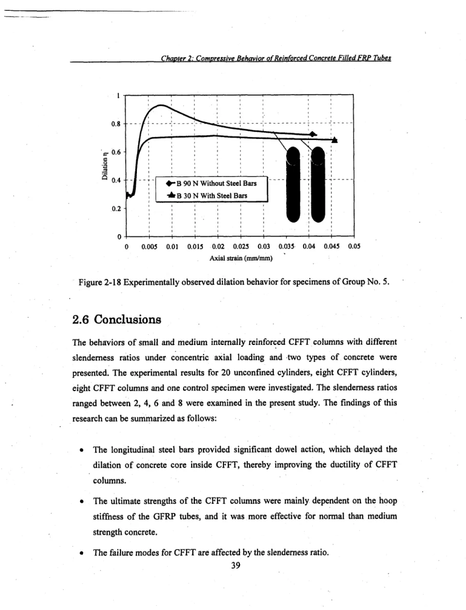
reinforcement 36 ^ 2.7 Dilation properties , 37
2.6 Conclusions 39
Chapter 3 Axial Load Capacity of Concrete-Filled FRP Tubes
Columns: Experimental versus Theoretical Predictions 41
3.1 Abstract 41
3.2 Introduction.. ...42 3.3 Objectives 43 3.4 Experimental Program 44
3.4.2 Specimen preparation.! 46 3.4.3 Instrumentation and test setup 47
3.5 Experimental Results 48 /
3.5.1 Stress-axial and hoop strains behavior 48
3.5.2 Failure modes 50 3.6 Theoretical Predictions of the Axial Load Carrying Capacity 55
3.6.1 Review of codes and design guidelines 55 3.6.2 ACI 440.2R-08 guide for the design and construction of externally bonded
FRP systems 56 3.6.3 Canadian Standard Association CAN/CSA-S6-06-Canadian Highway
Bridge Design Code 57 3.6.4 Canadian Standard Association CAN/CSA-S806-02-Building Code 58
3.6.5 Theoretical versus experimental confined concrete compressive strength 5 8
3.6.6 Proposed confinement model for CFFT 60 3.6.7 Predicted versus experimental values of the axial load carrying capacity 63
3.6.8 Modified equations for the axial load resistance of the CFFT columns 68
3.7 Conclusions ; 73
Chapter 4 Nonlinear Stability Analysis of Concrete Filled FRP-Tubes
Columns: Experimental and Theoretical Investigation 75
4.1 Abstract 75
4.2 Introduction and Background 76 4.3 Research Significance 77 4.4 Experimental Program 78
4.4.1 Materials .. 78
4.4.2 Test specimens 79 4.4.3 Instrumentations and test set-up 81
4.5 Test Results and Discussion . . 83
4.5.1 Failure modes 83 4.5.2 Ultimate load carrying capacity and slenderness ratio effect 84
4.5.3 Load-deformation characteristics of CFFT columns 88 4.5.4 Effect of concrete compressive strength and FRP tube thickness 93
4.6 Theoretical Investigation 95
4.6.1 Buckling loads 96 4.6.2 CFFT columns strength curve 99
4.6.3 Design example 101 4.7 Conclusions.,... . 103
Chapter 5 Flexural Behaviour of Reinforced CFFT Beams 104
5.1 Abstract .. 104
5.2 Introduction and Background 105 5.3 Experimental Program 111 5.3.1 Materials HI 5.3.1.1 Concrete I l l 5.3.1.2 Reinforcing steel.. 112 5.3.1.3 FRP bars .112 5.3.1.4 FRP tubes 114 5.3.1.5 Mechanical properties of the FRP tubes 116
5.3.1.5.1 Axial tension test 116 5.3.1.5.2 Axial compression test 118
5.3.2 Test specimens 120 5.3.3 Fabrication of specimens 122
5.3.4 Instrumentation... ...124
5.3.5 Test setup 126 5.4 Test Results and Discussions 129
5.4.1 General behaviour.... 129 5.4.2 Cracking and yield loads 129 5.4.3 Load-deflection response 133 5.4.4 Load-strain relationships 142
5.4.4.1 The flexural longitudinal compression and tension strains 142
5.4.4.2 The flexural hoop strain response 147 5.4.4.3 The shear strain rosette response 148 5.4.5 Failure modes and crack patterns 153 5.5 Effect of Test Parameters on Flexural ,Strength and Ductility .. 164
5.5.1 Effect of type of transverse reinforcement 164 5.5.2 Effect of type of longitudinal reinforcing bars 166 5.5.3 Effect of reinforcement ratio of FRP tubes 166 5.5.4 Effect of concrete compressive strength.. 169
5.6 Theoretical Analysis 171 5.6.1 Cracking moment of RCFFT beams 172
5.6.2 Theoretical development for yield and ultimate moment of test RCFFT
beams * i 175
5.6.3 Defection calculation of steel and FRP-RCFFT beams 186 5.6.3.1 Review of deflection formulas for steel and FRP-RC members 187
5.6.3.2 Evaluation of moment of inertia equations for deflection prediction of
RCFFT beams 191 5.6.3.3 Modified Branson's equation for steel-RCFFT beams 192
5.6.3.4 Modified Branson's equation for FRP-RCFFT beams 194
5.6.3.5 Proposed equation for FRP-RCFFT beams 198 5.6.3.6 Experimental verification of the modified and proposed equations 198
5.7 Conclusions 203
/
Chapter 6 Behavior of Concrete-Filled FRP Tubes Columns under
Eccentric Loads 205
6.1 Abstract 205
6.2 Introduction 206 6.3 Experimental Program. 207
6.3.1 Materials.... • 207
6.3.1.1 GFRP'tubes 207 6.3.1.2 Concrete 207 6.3.2 Reinforcing steel 209 6.3.3 Test matrix and specimen preparation 210
6.3.4 Test setup 212 6.4 Test Results and Discussion 214
6.4.1 Axial and lateral strain behaviour 214 6.4.2 Load-strain relationship of internal reinforcements 215
6.4.3 Axial and horizontal deformation : 218 6.4.4 Failure modes ... 221
6.4.5 Interaction diagram 224 6.5 CONCLUSIONS 226
Chapter 7 Assessment of Confinement Models for Concrete
Confined with FRP Tubes . 227
7.1 Abstract 227
7.2 Introduction 22 8
7.3 Review of Strength Models of FRP- Confined Concrete 229
7.4 Experimental Work 232 7.5 Assessment of Selected FRP-Confined Models 234
7.6 Conclusions 240
Chapter 8 Summary and Conclusions 241
.8.1 Summary 241 8.2 Conclusions 242
8.2.1 Reinforced CFFT columns ...243 8.2.1.1 Short CFFT columns under concentric loading 243
8.2.1.3 Short CFFT columns under eccentric loading 245
8.2.2 Reinforced CFFT beams 246 8.3 Recommendations for Future Work 258
List of Tables
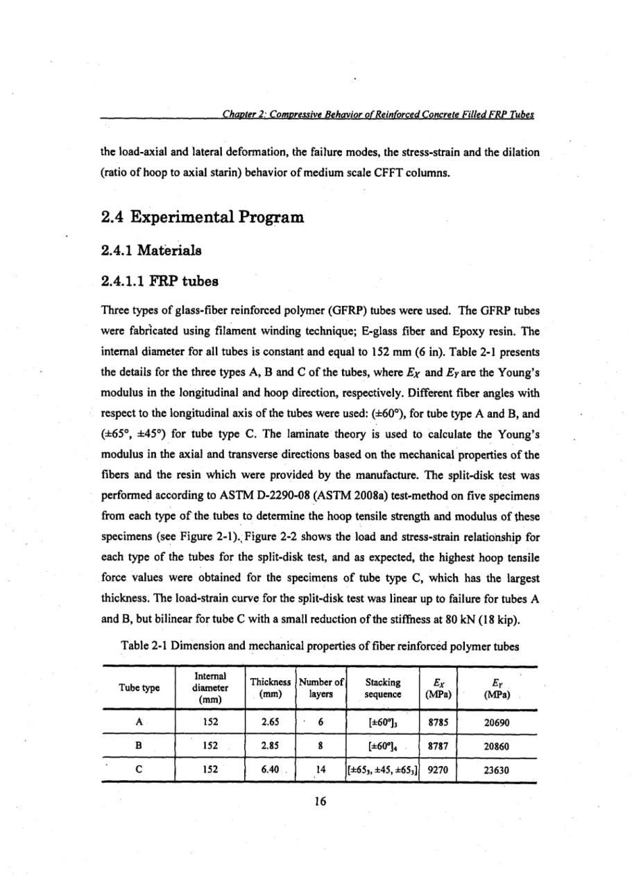
Table 2-1 Dimension and mechanical properties of fiber reinforced polymer tubes 16
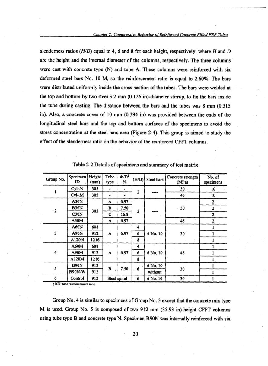
Table 2-2 Details of specimens and summary of test matrix 20
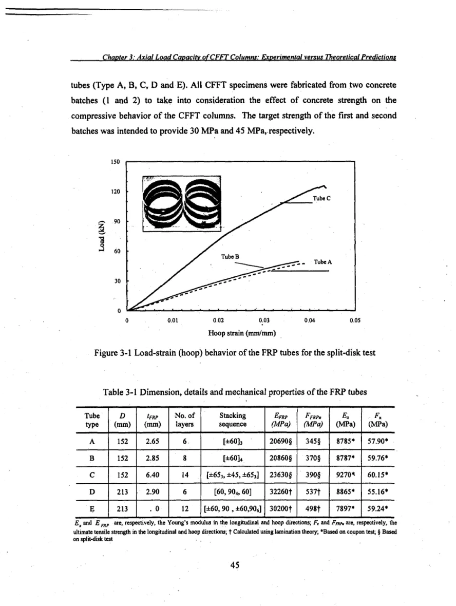
Table 2-3 Test results 24 Table 3-1 Dimension, details and mechanical properties of the FRP tubes 45
Table 3-2 Details of specimens and test results for the confined strength 52 Table 3-3 The experimental and theoretical results at the yield and maximum load levels... 69
Table 4-1 Dimension and mechanical properties of fiber-reinforced polymer tubes 79 Table 4-2 Configuration and characteristics of the tested specimens and test results 80
Table 5-1 Mix proportion of concrete I l l Table 5-2 Properties of reinforcing steel bars ....; 113
Table 5-3 Properties of reinforcing FRP bars 115 Table 5-4 Mechanical and physical properties of fibres and resin 115
Table 5-5 Dimension and details of the GFRP tubes 116 Table 5-6: Test matrix and details of beam specimens 121 Table 5-7 Test results of RC and RCFFT beams 132 Table 5-8 Experimental and predicted cracking moment for test RCFFT beams 175
Table 5-9 The theoretical results of moment capacities, //and £ values 183
Table 6-1 Properties of reinforcing steel bars 209 Table 6-2 Details of specimens and summary of test matrix 212
Table 6-3 Test results for the eccentrically and concentrically loaded CFFT columns 214
Table 7-1 Existing confining models for FRP-confined concrete 230
Table 7-2 Test matrix and specimens details... 233
Table 7-3 Experimental test results..., 234 Table 7-4 Performance of selected confined models and compression with test data 236
List of Figures
Figure 2-1 Test procedures for split-ring test 17 Figure 2-2 Load and strain -strain relationship for split-disk test 18
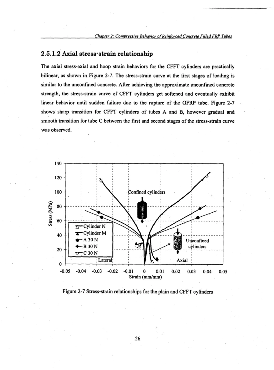
Figure 2-3 Fabrication of CFFT cylinders... 21 Figure 2-4 Fabrication of CFFT columns 22 Figure 2-5 Test setup for concentric axial load 23 Figure 2-6 Failure mode of CFFT cylinders 25 Figure 2-7 Stress-strain relationships for the plain and CFFT cylinders 26
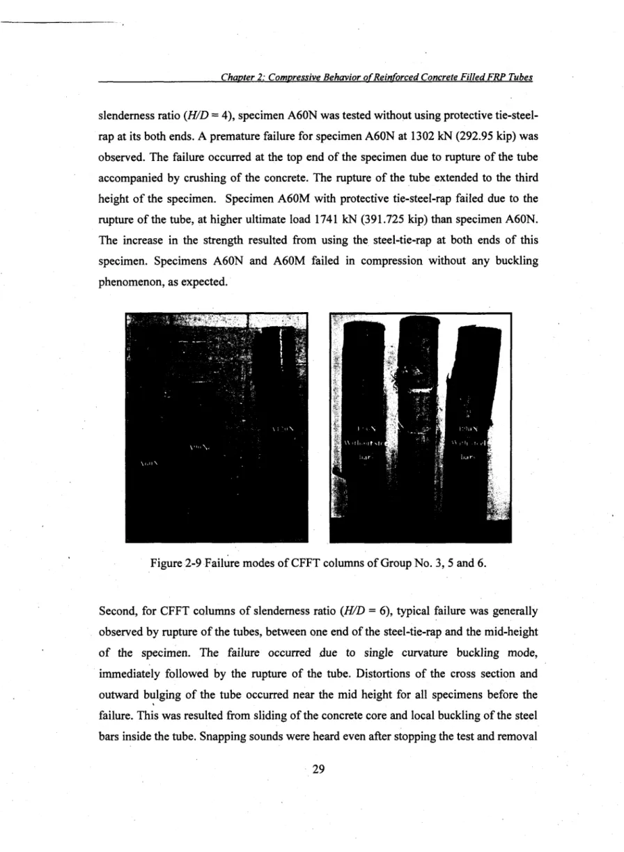
Figure 2-8 Experimentally observed dilation behavior for CFFT cylinders 28 Figure 2-9 Failure modes of CFFT columns of Group No. 3, 5 and 6 29 Figure 2-10 Stress-strain relationships for specimens of Group No. 3 31
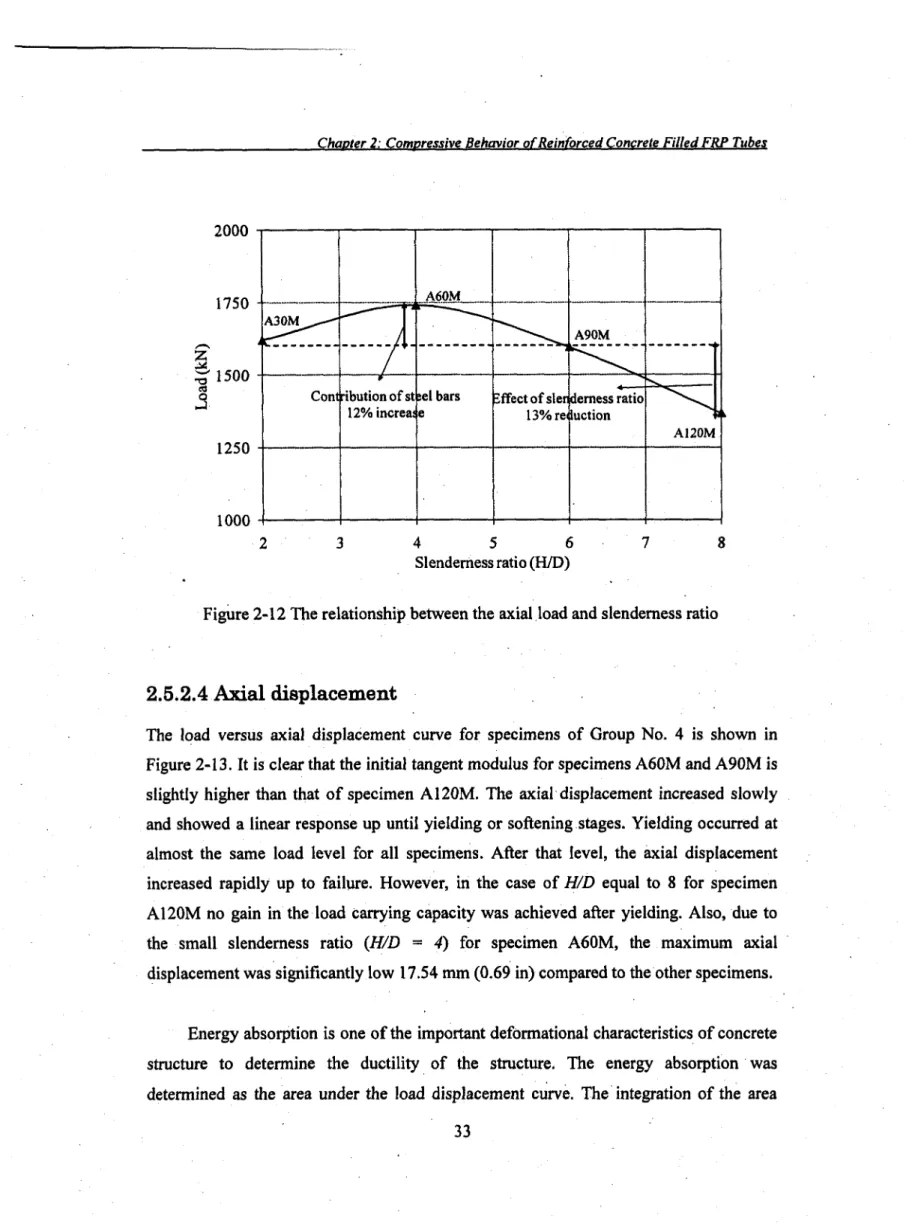
Figure 2-11 Stress- strain relationships (Group No. 5 and 6) 32 Figure 2-12 The relationship between the axial load and slenderness ratio 33
Figure 2-13 Axial load-axial displacement relationships ; ...35
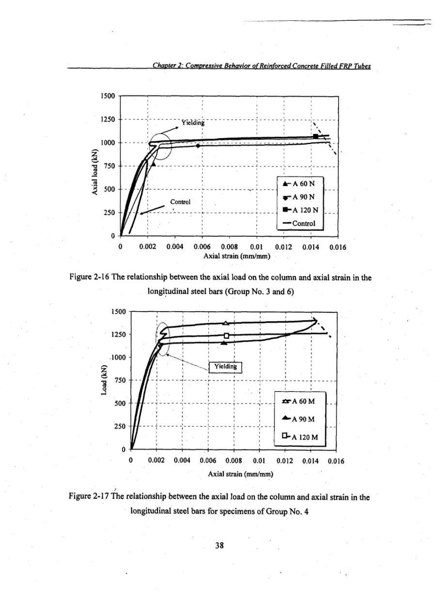
Figure 2-14 Axial Load-axial displacement relationships 35 Figure 2-15 Load-lateral displacement relationships 36 Figure 2-16 The relationship between the axial load on the column and axial strain
in the longitudinal steel bars (Group No. 3 and 6) 38 Figure 2-17 The relationship between the axial load on the column and axial strain
in the longitudinal steel bars for specimens of Group No. 4 38 Figure 2-18 Experimentally observed dilation behavior for specimens of Group
No. 5 39 Figure 3-1 Load-strain (hoop) behavior of the FRP tubes for the split-disk test . 45
Figure 3-2 Typical steel cages for CFFT specimens 47
Figure 3-3 Schematic of the test setup 48 Figure 3-4 Stress-strain behavior of CFFT specimens 51
Figure 3-5 The typical load-axial strain in the longitudinal steel bars relationships
for the reinforced CFFT columns 53 Figure 3-6 Failure mode of CFFT cylinders 54 Figure 3-7 Failure modes of CFFT columns 54 Figure 3-8 Predicted-versus-experimentally observed ultimate strength for
different confinement models (Series-I) 62 Figure 3-9 Predicted-versus-experimentally observed ultimate and yield loads 67
Figure 3-10 In-place confined strength of concrete-versus-FRP volumetric ratio 70 Figure 3-11 Load-displacement behavior for RC and FRP confined concrete
columns .... -72 Figure 3-12 Predicted-versus-experimentally observed yield load 72 Figure 4-1 Test specimens ; ... 81
Figure 4-2 Instrumentation and test setup 82 Figure 4-3 (a) Failure modes of CFFT specimens 85
Figure 4-4 Experimental ultimate load carrying capacity-versus-slenderness ratios
(kl/r) 86 Figure 4-5 Load-axial displacement behavior of CFFT columns 90
Figure 4-6 Load-lateral displacement behavior of CFFT columns . 92 Figure 4-7 Effect of various parameters on the ultimate strength of CFFT columns 94
Figure 4-8 Effect of the slenderness ratio on the critical buckling stress 100
Figure 4-9 Critical slenderness ratio 102 Figure 5-1 Stress-strain relationship for concrete 112
Figure 5-2 types of steel reinforcing bars and test set up 113 Figure 5-3 Stress-strain relationships for the steel reinforcement 113
Figure 5-4 Sand coated GFRP reinforcing bars 115 Figure 5-5 Filament wound GFRP tubes 115 Figure 5-6 Test procedures for coupon tension test.. 117
Figure 5-7 Stress-strain behaviour of the FRP tubes for the coupon tensile test 118
Figure 5-8 Test procedures for coupon compression test 119 Figure 5-9 Stress-strain behaviour of the FRP tubes for the coupon compression
Figure 5-10 FRP and cardboard tubes for beam specimens. 123 Figure 5-11 Typical steel and glass FRP cages for RC and RCFFT beams 124
Figure 5-12 Instrumentation of the reinforcing bars with strain gauges 125 Figure 5-13 Different types of instrumentation for the beam specimens 126
Figure 5-14 Steel frame of the test setup 126 Figure 5-15 Schematic of test setup for RCFFT and control beams 127
Figure 5-16 Overview for the test setup 128 Figure 5-17 Moment-curvature relationships for RC and RCFFT beams 131
Figure 5-18 Load-deflection curves for Specimens (CO-S-N, COS-S-N and
D-S-N) 135 Figure 5-19 Load-deflection curves for Specimens (CO-G-M, COS-G*N and
D-G-M) 135 Figure 5-20 Load-deflection curves for Specimens (D-S-N and D-G-N) 137
Figure 5-21 Load-deflection curves for Specimens (D-S-M and D-G-M) 137 Figure 5-22 Load-deflection curves for Specimens (D-G-N and E-G-N) 139 Figure 5-23 Load-deflection curves for Specimens (D-G-M and E-G-M) 139 Figure 5-24 Load-deflection curves for Specimens (D-S-N and E-S-M) 140 Figure 5-25 Load-deflection curves for Specimens (D-G-N and D-G-M) 141 Figure 5-26 Load-deflection curves for Specimens (E-G-N and E-G-M) 141 Figure 5-27 Load-flexural compression and tension relationships (Series 1) 144 Figure 5-28 Load-flexural compression and tension relationships (Series 2) 144 Figure 5-29 Strain profile at mid-span section of control and CFFT beams (Series
No. 1) 145 Figure 5-30 Strain profile at mid-span section of control and CFFT beams (Series
No. 2) 146 Figure 5-31 Mid-span hoop strain of reinforced CFFT beams (Series No. 1) 149
Figure 5-32 Mid-span hoop strain of reinforced CFFT beams (Series No. 2) 150 Figure 5-33 load-strain rosette relationships at mid-height of tested beams (Series
1 ) 151 Figure 5-34 load-strain rosette relationships at mid-height of tested beams (Series
Figure 5-35 Failure mode and concrete crack pattern of RC beam CO-S-N 154 Figure 5-36 Failure mode and concrete crack pattern of RC beam CO-G-M 154 Figure 5-37 Failure mode and concrete crack pattern of RC beam COS-S-N 156 Figure 5-38 Failure mode and concrete crack pattern of RC beam COS-G-M 156 Figure 5-39 Failure mode and concrete core crack pattern of RCFFT beam D-G-N 157 Figure 5-40 Failure mode and concrete core crack pattern of RCFFT beam D-S-N 157 Figure 5-41 Failure mode and concrete core crack pattern of RCFFT beam D-G-M 160 Figure 5-42 Failure mode and concrete core crack pattern of RCFFT beam D-S-M 160 Figure 5-43 Failure mode and concrete core crack pattern of RCFFT beam E-G-N... 161 Figure 5-44 Failure mode and concrete core crack pattern of RCFFT beam E-G-M 161
Figure 5-45 Load-end rotations of RC and CFFT beams . 162 Figure 5-46 Load-concrete end slippages of reinforced RCFFT Beams 163 Figure 5-47 Effect of type of transverse reinforcement on the flexural strength 165
Figure 5-48 Effect of type of transverse reinforcement on the energy absorption 165 Figure 5-49 Experimental flexural strength versus Young's modulus of bars 167
Figure 5-50 Energy absorption versus Young's modulus of bars 167 Figure 5-51 Experimental flexural strength versus FRP-tube reinforcement ratio... 168
Figure 5-52 Energy absorption versus FRP-tube reinforcement ratio. 168 Figure 5-53 Experimental flexural strength versus concrete compressive strength 170
Figure 5-54 Energy absorption versus concrete compressive strength 170
Figure 5-55 The Typical cross section of the RCFFT beams 172 Figure 5-56 Details of RCFFT beam cross section and its strain and stress profiles 178
Figure 5-57 The experimental to theoretical monument ratio versus the neutral
axis depth ratio . 182 Figure 5-58 The experimental to the theoretical moment capacities of RCFFT
beams .. 186 Figure 5-59 Deflected shape of simply supported beam subjected to two equal
concentrated loads 187 Figure 5-60 Effective to gross moment of inertia versus Ma / Mcr, (Steel-RCFFT
Figure 5-61 Effective to gross moment of inertia versus Ma / Mcr, (FRP-RCFFT
beams) 197 Figure 5-62 Effective to cracking moment of inertia versus Ma/Mcr,
(FRP-RCFFT beams) . 199 Figure 5-63 Mid-span moment versus deflection measurements and predictions 202
Figure 6-1 stress-strain curve for the split-disk 208 Figure 6-2 Stress-strain curve for coupon tensile test ; 208
Figure 6-3 Stress-strain relationships for the steel reinforcement 209
Figure 6-4 Formwork and casting procedures 211 Figure 6-5 Test set up for eccentric axial load 213 Figure 6-6 Load-axial and lateral strains relationships of Specimen B90SN15 216
Figure 6-7 Load-axial and lateral strains relationships of Specimen B90SN30 216 Figure 6-8 Load-axial and lateral strains relationships of Specimen B90SN45 217 Figure 6-9 Load-axial and lateral strains relationships of Specimen B90SN60 217 Figure 6-10 Load-strain relationships of internal steel reinforcements (tension-side) 218 Figure 6-11 Load-axial deformation relationships for the eccentrically and
concentrically loaded CFFT columns 220 Figure 6-12 Load-horizontal deformation relationships for the eccentrically and
concentrically loaded CFFT columns 220 Figure 6-13 Failure modes of eccentrically loaded CFFT column specimens 223
Figure 6-14 Load-eccentricity relationships 225 Figure 6-15 Experimentally interaction diagram for CFFT columns 225
Chapter 1 Introduction
1.1 Introduction
The corrosion of steel reinforcement in an aging highway and marine infrastructure is a major problem currently facing the transportation and civil engineering structure community. Further, the existing of these structures in harsh environments has resulted in steady deterioration that shortens the lifetime serviceability of concrete structures. Harsh environments, such as those found in cold regions or Canadian climates, may expose structures to freeze-thaw cycles, marine sea spray or winter de-icing salts. In Canada and the United States, maintenance and replacement costs of bridge and marine substructures are measured in billions of dollars. Government agencies and industrial firms are looking for infrastructure systems that are stronger, last longer, are more resistance to corrosion, cost less to build, maintain and repair. Engineers all over the world are challenged and in search of new and affordable construction materials as well as innovative approaches and systems to problem solving.
Since the 1970s, research projects and field studies have been conducted on different methods for protecting reinforced concrete structures from deterioration and corrosion damage. Several techniques, including epoxy coating of reinforcing bars, cathodlic protection, increased concrete cover thickness, polymer concrete overlays have been used to inhibit or eliminate corrosion. None of these techniques, however, has been proven to be cost-effective or a long-term solution. A significant research effort over the past twenty years has shown that fibre reinforced polymer (FRP) materials can be effectively used to reinforce and/or strengthen deteriorated or understrength reinforced concrete structures. FRP reinforcement is made from high tensile strength fibres such as carbon, glass, and aramid embedded in polymeric matrices and produced in the form of bars, tubes, grids, in a wide variety of shapes and characteristics. FRPs are corrosion-free
materials and have been used worldwide for new structures to avoid the deterioration of concrete structures caused by corrosion of steel reinforcement.
Over the past decade there has been increased consideration and field use of composites for the rehabilitation of existing structural components and systems. However, despite similar levels of efforts being made for the introduction of composites into new construction applications there has been only limited success with most projects being at the level of demonstrations, rather than bid competitively with conventional materials, or being specified because of the inherent and essential advantages of FRP composites over conventional materials. In part their application in new construction has been limited due to high costs in comparison with components fabricated from conventional materials such as concrete and steel. Further there is a reluctance to use these materials for primary structural elements in new construction without sufficient data on long-term structural response and durability. There is however, no doubt, that these materials have significant advantages for use in new construction ranging from lighter weight which would translate to greater ease in construction without heavy construction equipment and use of smaller sub-structural elements, to their greater capacity to meld form and function thereby providing for ease in integration of aesthetics with functionality (Karbhari 2004).
In the last decade, considerable efforts have been made to apply FRP composites in the construction industry, and recently, structural applications of FRP composites started to appear in civil infrastructure systems. FRP composite materials have been used as internal and external reinforcement in the field of civil engineering constructions. It has been used as internal reinforcement for beams, slabs and pavements (Masmoudi et al. 1998; Rizkalla et al 2003; Benmokrane et al. 2006), and also as external reinforcement for rehabilitation and strengthening different structures (Demers and Neale 1998; Teng et al. 2002). Application of FRP in infrastructural systems has come about as a result of the many desirable characteristics of composites that are superior to those of conventional materials such as steel, concrete, and wood. FRP composites are very attractive materials to structural engineers due to their high specific stiffness and high specific strength. The
high corrosion resistance of FRP composites makes them ideal alternative materials to resolve a number of problems that the worldwide infrastructures are now facing.
To most effectively utilize the advantages of FRP materials, which are light weight and improve constructability, innovative structural designs are needed which either incorporate "composites-efficient" forms or which combine these materials with conventional ones. One promising innovative structural system is concrete-filled FRP tubes (CFFT). In recent years, CFFT system has been widely studied for their use in civil infrastructure. In the early 1980s, the concept of CFFT was proposed by Fardis and KhalilL 1981 and 1982, who analyzed the behaviour of circular and rectangular FRP tube-encased concrete columns and beams. CFFT are constructed by simply filling prefabricated FRP tubes with concrete. CFFT technique represents a formwork-free, steel-free, and corrosion-resistant alternative for construction of new infrastructure. This system provides an excellent alternative to conventional reinforced concrete or steel components for several structural applications in aggressive and corrosive environments, including fender piles, bridge girders and piers, poles, and overhead sign structures. The most common characteristics of the integrated systems are as follows:
• FRP shape acts as permanent form for concrete; hence, will save the cost of formworks involved in conventional cast-in-place or pre-cast industries.
• Main reinforcement for concrete is provided externally by the FRP shape, even though additional reinforcement of other types of materials such as steel may be provided internally. In concrete-filled FRP tubes, the tube acts as reinforcement for both shear and flexure, utilizing the multi-direction fibre orientation. This would save the time and cost involved in conventional construction in assembling longitudinal rebars together with stirrups. The closed composite shells provide passive confinement to the concrete, which significantly improves the strength and ductility.
• Depending on the nature of loading, the capacity and performance of the system may depend on the composite action between the concrete and FRP shape.
• The system lends itself to optimization based on material properties of each component. The hybrid system provides the designers with several flexible
parameters, which can be controlled to achieve optimum design in individual applications including type of fibres, orientation of the fibres, number of layers in the composite shell, and the concrete wall thickness.
• The contained concrete, in case of concrete-filled tubes, is protected from moisture intrusion that could otherwise deteriorate the concrete core
• Reduces the expense of maintaining new infrastructure • Increases the life span and safety of new infrastructure
The general process used to manufacture FRP tubes is one of placing and retaining fiber reinforcements in the direction and form needed to provide the finished product its desired shape and properties. It can be done by pultrusion, filament winding, centrifugal casting or resin infusion. Pultrusion is a highly automated, low-labor, closed-mold process for manufacturing FRP shapes having a uniform cross section. The process is well suited for high-volume commercial production of both custom and standard shapes because it can be operated continuously.
The filament winding technique is the most common manufacturing method for producing FRP tubes. Filament winding was invented in 1946 and incorporated into missile applications in the 1950s (Daniel and Ishai 1994). Filament winding is an automated low-labor process typically used to manufacture cylindrical, conical, parabolic, box beam, and other FRP tube shapes. Such shapes are made by continuously wrapping resin-impregnated fibre reinforcements around a mandrel. In basic terms, the process involves a winding machine that pulls dry fibre reinforcement from supply racks through a resin applicator system and winds the wet fibre around the mandrel. In the filament winding process, the placement of the primary fibre-glass reinforcement is tightly controlled and can be oriented in either a circumferential or longitudinal direction or anywhere in between as needed to develop the necessary strength properties in the circumferential (hoop) direction. Controlling fibre tension and winding angle is an integral part of the filament winding process because these factors greatly determine the performance of the finished FRP tube is usually somewhat rougher than the smooth interior.
The use of FRPs in new structures is still somewhat limited, mainly because of their relatively higher initial cost, lack of design codes in some area. However, CFFT technique provides an emerging and promising system for a variety of structural applications in which the tubes serve as structural formwork. Circular CFFT have already been implemented in the field as bridge piers, marine piles, and girders, where FRP tubes were essentially the sole reinforcement for the system (Mirmiran and Shahawy 1996; Mirmiran, et al., 1999; Seible et al. 1999; Fam et al 2003a, and b; Zhao et al. 2004). Fam et al. 2003c presented eight field applications of a total 1162 CFFT composite piles in marine environments in different location of the United States of America. These piles were without internal reinforcements. The diameter of the used CFFT composite piles ranged from 300 mm to 450 mm, and the length ranged from 14 m to 25 m. Whereas, these composite piles were used as a fender walls to protect the piers of a bridge in a lake; to support new docking facilities; in a structural application to support a wharf extension; dauphin clusters; structural battered. In other applications, FRP tubes have been used in conjunction with internal steel reinforcement (Pando et al. 2003). In 2000, the Virginia Department of Transportation (VDOT) employed the CFFT composite piles for an entire bent of new route 40 Bridge over the Nottoway River in Sussex Country, Virginia. Also, in 2001, VDOT started a bridge replacement project at the Route 351 Bridge crossing of the Hampton River in Hampton, Virginia. The VDOT has decided to use a CFFT composite pile. Internal longitudinal steel reinforcement was included in the used CFFT composite pile to increase the flexural stiffness (Pando et al. 2003). In addition, the concept of concrete-filled FRP tubes has been used in field applications as bridge girders. Whereas, the flexural behaviour of large and full-scale a two-span concrete-filled carbon FRP tube bridge girders combined with either a conventional RC deck or a lightweight GFRP modular deck was investigated by Karbhari et al. 2000. Based on the findings of the previous research work, a field application of CFFT with carbon FRP tubes as bridge girders was implemented to construct the Kings Stormwater Channel Bridge, along Highway 86, near the Saltan Sea. (Burgueno et al. 1998; Seible et al. 1999; Karbhari et al. 2000; Zahao et al. 2000). The bridge is 20 m long and comprises a two-span
slab-on-girder system for the superstructure, which in turn comprises six longitudinal 340 mm diameter CFFT girders with 9.50 mm thick carbon FRP tubes.
The axial and flexural studies on CFFT, however, have mostly been conducted without using internal reinforcements. Although valuable research has been conducted on CFFT under flexural and axial loads, and in some other areas it has been quite limited, leaving research gaps in need of further investigations to introduce appropriate provisions in guidelines and codes for the design issues of CFFT under axial and flexural loads. The main focus of the present study is on the reinforced concrete-filled FRP tubes. It basically consists of a filament-wound FRP tubes filled with concrete and reinforced internally with steel or FRP rebar. The scope is primarily focused on the structural feasibility of reinforced CFFT. The following issues are examined:
- Confinement of concrete with FRP tubes.
- Composite action of FRP tube, internal rebar and concrete in columns under concentric and eccentric loads.
- Composite action of FRP tubes internal rebar and concrete in beams under flexural load. - Comparison of its behaviour with conventional RC columns and beams.
- Design issues such as ultimate load carrying capacity and deformation.
1.2 Objectives and Originality
Recently, the concrete-filled FRP tubes (CFFT) technique has been used successfully for different concrete structures in the field of civil engineering. Nevertheless, the ultimate load carrying capacities of short and slender reinforced CFFT columns have not yet been fully explored. Several codes and design guidelines addressing the strengthening and rehabilitation issues of RC columns using confinement by FRP sheets have been recently published. Most of the design provisions for predicting the ultimate axial load incorporated in these codes and design guidelines are based on the design formulas of members reinforced with conventional steel considering some modification. On the other hand, the design provisions for predicting the yield and ultimate moment capacities as well as the load-deflection response of the circular reinforced CFFT under flexural load have not yet
been introduced in codes and design guidelines. For example, the recommended equations for estimating the effective moment of inertia for deflection calculation in the current codes and design guidelines do not take into consideration the effect of confinement.
This present study is aimed at providing basic technical information on axial and flexural behaviour of CFFT members. A number of research objectives are identified and systematically listed below in the two stated areas for the proposed experimental and analytical development.
1. Reinforced CFFT columns a. Short
• To evaluate the compression behavior of small and medium-scale CFFT columns under pure axial load and eccentric load using new filament wound GFRP tubes. • To evaluate the confinement models and the design equations provided by the three
different North American codes and design guidelines (ACI Committee 440.2R 08, CAN/CSA-S6-06 and CAN/CSA-S806-02), for the predictions of the confined concrete compressive strength and the ultimate load capacities of the short CFFT columns.
• To propose a new confinement model and to introduce appropriate modifications to the existing design equations for the reinforced and unreinforced short (non-slender) CFFT columns.
b. Slender
• To investigate the influence of the slenderness ratio of CFFT columns on the critical buckling load and the ultimate capacity of such columns.
• To investigate the relative importance of internal reinforcement, concrete compressive strength and thickness of the FRP tubes on the buckling mode of failure of CFFT columns.
• To verify the accuracy of existing critical buckling load formulas and then to propose a threshold for the slenderness ratio for CFFT columns.
2. Reinforced CFFT beams
conventional RC beams with and without steel spiral reinforcement.
• To evaluate the effects of the following specific experimental parameters on the flexural response of CFFT beams:
1) The effect of type of the internal reinforcements (steel or GFRP bars) on the flexural performance of RCFFT beams.
2) The effect of the FRP tube thickness
3) The effect of concrete compressive strength by using the two types of concrete batches.
• To develop an analytical procedure to predict the yield and ultimate moment of RCFFT beams.
• To examine the validity of the available design provisions for predicting the load-deflection response of CFFT beams.
• To develop new equations and update the existing design equations for predicting the effective moment of inertia of CFFT beams reinforced with steel or GFRP bars.
1.3 Methodology
To achieve the objectives of this research, experimental and analytical programs were designed. The experimental program consisted of two types of structural members. The first and second type comprised reinforced concrete filled FRP tubes columns and beams, respectively.
Experimental investigations of the axial behaviour of the CFFT columns have generally been carried out without using internal longitudinal reinforcement. While there is abundant experimental and theoretical research information on the small (cylinder) scale specimens, there are few data on the behaviour of large scale CFFT columns. In addition, limited experimental works have been carried out on specimens with internal longitudinal reinforcements.
Therefore, as regards columns, 35 CFFT columns and five control reinforced concrete columns of different size and with internal longitudinal reinforcements were cast
and tested under concentric and eccentric loading in the experimental investigation of this study. The experimental program of the CFFT columns was characterized to four stages. The first and the second stage were designed to study the behaviour of short and long CFFT columns respectively under concentric loads, while the third stage was focused on the behaviour of short CFFT columns under eccentric loads. The fourth stage was developed to serve as control conventional spiral-steel reinforced concrete columns for CFFT specimens.
The analytical investigation for CFFT columns included analysis test results using the different available design provisions of axial load capacity pertinent to members confined with FRP materials. The results of each analysis were compared to the experimental values. Based on the results of this comparison and the experimental findings, proposed modifications to the North American codes and design guidelines for the predictions of the ultimate load capacities of the short CFFT columns are presented. On the other hand, for the slender CFFT columns, simplified formula for the limit slenderness ratio was proposed for the design purposes. The predicted value according to the proposed formula agrees with the observed critical slenderness ratio and with the recommended value in the literature.
As regards beam, the test beams were divided into two series. The first and second series were cast using normal and medium concrete strength, respectively. Each series included five beams, one conventional reinforced concrete (RC) circular beams without spiral reinforcement and one RC beam with spiral reinforcement, while the remaining three specimens were RCFFT. The specimens of each series were reinforced with steel or glass FRP bars with the same reinforcement ratio. Two types of FRP tubes different in thickness were used as stay-in-place form works for the beam specimens.
The analytical investigation for CFFT beams included step by step simplified formulations to predict the yield and ultimate moment of tested RCFFT beams. In addition, the experimental values of the moment-deflection response of tested CFFT beams were analyzed and compared with the available design equations. Based on the
results of this comparison and the experimental findings, new equations and proposed modifications to the existing equations for predicting the effective moment of inertia in the literature and codes for the predictions of the moment-deflection response of tested CFFT beams are presented.
1.4 Organization of the Dissertation
This dissertation consists of eight chapters. The following is a brief description of the contents of the thesis:
Chapter T. This chapter serves as an introduction, outlines the advantages and applications of concrete filled FRP tubes in civil engineering infrastructures, followed by the objective and scope of this study.
Chapter 2: This chapter presents the first paper in this dissertation, which is titled "Compressive Behavior of Reinforced Concrete Filled FRP Tubes." It presents the results of an experimental investigation on the axial behaviour of 16 small- and medium-scale reinforced CFFT columns. Factors influencing the strength and ductility enhancement such as: the effect of laminate thickness, concrete strength and presence of longitudinal steel bars are addressed. Research findings indicate the longitudinal steel reinforcements enhance the ductility of CFFT columns. The ultimate strength of the CFFT is mainly dependent on the stiffness of the FRP tubes in the hoop direction, and it is more effective for normal concrete strength.
Chapter 3: This chapter presents the second paper in this dissertation, which is titled "Axial Load Capacity of Reinforced Concrete-Filled FRP Tubes Columns: Experimental versus Theoretical Predictions" The purpose of this study is to present a constructive critical review of the state-of-the-art design methodologies available for the case of confined concrete RC short columns using FRP tubes and to indicate a direction for future developments. Comparisons between the experimental test results and the theoretical predictions values by the three North American codes and design guidelines are performed. Based on the test results and the analysis a new confinement model is
proposed for the confined concrete compressive strength of the CFFT cylinders. Also, the design equations are modified to accurately predict the ultimate and yield loads capacities of internally reinforced and unreinforced short CFFT columns.
Chapter 4: This chapter presents the third paper in this dissertation, which is titled "Nonlinear Stability Analysis of Concrete Filled FRP-Tubes Columns: Experimental and Theoretical Investigation" In this study, 18 CFFT columns of different heights, 305, 608, 912, 1216 and 1520 mm and 4 control RC columns were tested under uniaxial compression load. The main objective of this paper is to investigate experimentally and theoretically the influence of the slenderiiess ratio of CFFT columns on the critical buckling load and the ultimate capacity of such columns. Simplified formula for the limit slenderness ratio was proposed for the design purposes of CFFT columns in this paper.
Chapter 5: This chapter describes the experimental program and the theoretical analysis conducted to test 10 control beams reinforced with FRP or steel bars in the longitudinal direction and with FRP tubes or spiral steel in the transverse direction. In this chapter the details of test specimens, materials, configurations, test setup, and instrumentations are given. The results obtained from the experimental investigation are presented in this chapter. The influence of each test parameter on the flexural behaviour of the tested beams is analyzed. A simplified analytical method is developed to predict the yield and resisting moments corresponding to the failure modes of the tested RCFFT beams. In addition, an analytical investigation to examine the validity of the available design provisions for predicting the load-deflection response of CFFT is conducted. The effective moments of inertia of the tested beams are analyzed using the different available code, manuals and design guidelines equations. The results of the analysis are compared with the experimental values. Based on the experimental data obtained in this study, new proposed equations and a modified expression for the effective moment of inertia of a simply supported CFFT beams reinforced with steel or GFRP bars are introduced. Finally, most of the content of this chapter are included in two papers.
Chapter 6: This chapter presents the sixth paper in this dissertation, which is titled "Behavior of Concrete Filled FRP Tubes Columns under Eccentric Loads." It presents
the results of an experimental investigation on the behaviour of CFFT columns under eccentric load. The new test setup is described in the experimental program. The results obtained from the experimental investigation are presented in this chapter. The test results for four CFFT columns tested with different eccentric values are compared to the test results of CFFT and RC columns tested under concentric load.
Chapter 7: This chapter presents the main contribution of the seventh paper in this dissertation, which is titled "Assessment of Confinement Models for Concrete Confined with FRP Tubes." In this chapter fourteen selected FRP-confmed models for prediction the ultimate strength of CFFT have been reviewed. A comparison between the experimental results and those predicted by the selected models is presented. The assessment has been based on the prediction of the ultimate axial strength of the CFFT specimens, rather than on its strain or whole stress-strain relationships.
Chapter 8: A summary of this investigation is given in this chapter. The chapter also presents the general conclusions drawn from the work presented in this dissertation. Recommendations for future research are also given.