A mechanism leading to γ’ precipitates with {111} facets and unusual
orientation relationships to the matrix in γ/γ’ nickel-based superalloys
Suzanne Vernier
a,b*,
Jean-Michel Franchet
b, Christian Dumont
cand Nathalie Bozzolo
aa MINES ParisTech, PSL – Research University, CEMEF – Centre de mise en forme des matériaux, CNRS UMR 7635, 1 rue
Claude Daunesse, 06904 Sophia Antipolis, France
b Safran SA, Safran Tech – Materials & Process Department, Rue des Jeunes Bois – Châteaufort, 78772 Magny-les-Hameaux,
France
c Aubert & Duval, Département R&D transformations, BP1, 63 770 Les Ancizes, France
*Corresponding author. suzanne.vernier@mines-paristech.fr
ABSTRACT
Cast-and-wrought heavily-alloyed γ-γ’ nickel-based superalloys may exhibit large recovered grains inherited from the ingot conversion and characterized by a high density of close-to-coherent micrometric γ’ precipitates. In the AD730TM
nickel-based superalloy, a previous work [18] highlighted a new interaction between such precipitates and a
recrystallization front passing through. This interaction resulted in γ’ precipitates with a close-to-twin orientation relationship to their recrystallized host grain. Called T-type precipitates, they were revealed to be {111} bounded plate-like particles. The present paper aims to clarify the mechanism whereby such precipitates form. The formation of T-type precipitates actually is part of a more global mechanism which also produces γ’ precipitates slightly misoriented from their surrounding matrix (C-type precipitates) and of same size and morphology as T-type precipitates. Both T and C type precipitates display {111} facets and are evidenced in the AD730TM, René65 and PER72 alloys, supporting the
idea that the mechanism can more generally occur in all low-lattice-mismatch γ-γ’ nickel-based superalloys. Finally, a scenario is proposed: T/C type precipitates form at the recrystallization front of grains sharing a <111> axis with the recovered grain they consume, and develop {111} facets and specific orientations which minimize the interfacial energy on both recrystallized and recovered sides.
I.
INTRODUCTION
1
Wrought polycrystalline γ-γ’ nickel-based superalloys are commonly used to manufacture aero-engine turbine 2
disks, thanks to their outstanding mechanical properties at high temperature [1,2]. Those alloys display γ grains
3
and γ’ precipitates of various sizes. The γ phase is a Face Centered Cubic (FCC) non-ordered solid solution, 4
while the γ’-Ni3(Al,Ti) phase has a L12 ordered cubic structure. At a few micrometers in size, primary
5
precipitates are the largest precipitates of the microstructure [3]. Derived from the as-cast microstructure and high
6
temperature billet forging sequences, they are useful for the grain size control since they pin grain boundaries 7
during subsolvus forging operations. Most of the time, primary precipitates lie on grain boundaries and are 8
incoherent with the surrounding γ matrix, which means that there is no matching at all between the γ’ and the γ 9
crystal lattices. Yet, the interaction between a recrystallization front and an incoherent precipitate is quite easy to 10
predict. When a moving grain boundary encounters a precipitate, its curvature is locally modified due to 11
capillarity effects, which is interpreted as a pinning force applied on the boundary and referred to as the Smith-12
Zener pinning force [4]. Then, if the grain boundary is subject to sufficient driving force to counteract the pinning
13
force, it will bypass the precipitate; otherwise it will halt at the precipitate. However, when a moving boundary 14
meets a coherent precipitate - which means that the γ and γ’ crystal lattices perfectly coincide at the γ/γ’ interface 15
[5] - the interaction can be much more complex. Indeed, because coherent interfaces have low energy values [6,7],
16
the maximum pinning force a coherent precipitate can enforce is twice that of an incoherent precipitate of the 17
same size [8,9]. Then, other phenomena which also allow the grain boundary to carry on moving and which are
18
more thermodynamically and/or kinetically interesting than the coherent precipitate bypass can occur. It was 19
reported in the literature that a coherent precipitate may be cut-through - so that the orientation of the precipitate 20
is changed to that of the growing grain [7,8] - or dissolved [10,11]. However, if the grain boundary driving force is
21
not sufficient to bypass, dissolve or cut-through the coherent precipitate, the grain boundary will halt at the 22
coherent precipitate which will then coarsen as a result of the interfacial energy equilibrium [8]. At a few hundred
23
nanometers to few nanometers in size, secondary and tertiary precipitates are always coherent with their 24
surrounding matrix. But much larger precipitates are also found coherent or close-to-coherent. First, Charpagne 25
et al. evidenced large primary precipitates with the same orientation as their surrounding matrix in the case of 26
heteroepitaxial recrystallization [12–14]. Second, cast-and-wrought heavily-alloyed γ-γ’ nickel-based superalloys
27
may exhibit unrecrystallized grains inherited from the ingot conversion process[15–17] where a high density of
28
micrometric close-to-coherent precipitates is found. These unrecystallized grains are characterized by 29
intragranular orientation gradients with more or less developed recovery cell structures; thus they will be called 30
recovered grains in the following text. Yet, in the AD730TM γ-γ’ nickel-based superalloy a previous work [18]
31
pointed out a new interaction between the close-to-coherent precipitates of the recovered grain and the 32
recrystallization front passing through. This interaction sometimes led to γ’ precipitates with a close-to-twin 33
orientation relationship to their recrystallized host grain. “Close to twin orientation relationship” means that the 34
γ’ and γ cubic lattice cells conform to a 60°<111> rotation within the 8.66° tolerance given by Brandon’s 35
criterion: both the misorientation angle and misorientation axis do not deviate more than 8.66° to the 60° angle 36
and <111> axis of the perfect twin boundary [18,19]. Such precipitates close to the twin orientation relationship
37
have been called T-type precipitates and revealed to be {111} bounded plate-like particles. Their size, 38
morphology and narrow orientation spread compared to the precipitates of the recovered grain have proved that 39
they do not result from a simple bypass by the recrystallization front but from a specific mechanism. The aim of 40
the present paper is to clarify this mechanism using EBSD data analyses. It is shown that the formation of T-type 41
precipitates is part of a more global mechanism which also produces precipitates with an orientation very close 42
to that of their surrounding matrix and of the same size and morphology as the T-type precipitates. These 43
precipitates are called C-type precipitates and rotated by few degrees around a <111> axis they have in common 44
with their surrounding matrix. T and C type precipitates are evidenced in the AD730TM, René65 and PER72
45
alloys, supporting the idea that the studied mechanism can more generally occur in all γ-γ’ nickel-based 46
superalloys with a low-lattice mismatch. Finally, a scenario is proposed for this specific mechanism which 47
allows a recrystallization front to get through a high density of close-to-coherent micrometric precipitates and 48
leads to γ’ precipitates with unusual morphologies and orientations. 49
II.
EXPERIMENTAL
50
In the present paper, five samples are analyzed. They are derived from different thermo-mechanical conditions 51
and from three different alloys: AD730TM, René65 and PER72. The PER72 alloy is an equivalent of the
52
Udimet720 alloy manufactured by the Aubert&Duval Company. All these polycrystalline γ-γ’ nickel-based 53
alloys are all heavily-alloyed, derived from the traditional cast-and-wrought route and characterized by a low 54
lattice mismatch [12,20] . Their chemical compositions are given in Table 1.
55
Three samples were cut out from AD730TM billets. Two of them were observed as-received. The third one,
56
referred to as the “AD730TM Lab-Forged sample”, was deformed at high temperature (compression test) then
57
treated for 4 hours at 1080°C in order to complete recrystallization. Hot-deformation and solution-58
treatment temperatures were both below the γ’ solvus temperature which is about 1110°C. The fourth and fifth 59
samples were cut out from René65 and PER72 billets and heat-treated for two hours at about 40° below their 60
respective γ’ solvus temperature. All the samples were ground with Si papers and polished with diamond 61
suspensions down to 1µm. To obtain a suitable surface quality for EBSD (Electron BackScatter Diffraction), 62
they were finally polished either by electropolishing (electrolyte: CH3OH-10% HClO4) or with a 0.02µm
63
colloidal silica solution on a vibratory machine. Observations were carried out with a Zeiss Supra40 Field 64
Emission Gun Scanning Electron Microscope operated at 15kV. The microscope is equipped with the 65
QUANTAX EDS/EBSD system from the Bruker Company which is composed of an XFlash 5030 Energy 66
Dispersive X-ray Spectrometer (EDS) and an e-FlashHR EBSD detector, both controlled by the ESPRIT®
67
software package. Some of the EBSD data post-treatments were performed using MTEX, a freely available 68
MATLAB toolbox [21].
69 70
III. RESULTS AND DISCUSSION
71 72
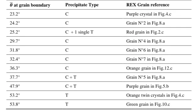
A. T and C type precipitates in the AD730TM alloy : the results of a single mechanism
73 74
T-type precipitates have been reported in the alloy AD730TM, in some recrystallized grains which had
75
extensively grown into a recovered grain and which shared a <111>axis with it [18]. Nevertheless, Fig.1 shows
76
that T-type precipitates are not the only type of precipitate which can be found in such recrystallized grains. 77
Indeed, some precipitates which are 2-3° misoriented from their host grain appear among the T-type precipitates 78
(Fig.1.a). These precipitates have a nearly rectangular shape in the sample section like the T-type precipitates 79
(Fig.1.b). Close to the orientation of their surrounding matrix, they will be called C-type precipitates in the 80
following text. The rectangular shapes of the C-type precipitates are parallel and also parallel to those of the T-81
type precipitates (Fig.1.b). On the {111} pole figure (Fig.1.d), the orientations of T and C type precipitates 82
(randomly selected) are compared to those of the host recrystallized grain and the recovered grain. First, the 83
orientations of the two precipitate types appear very homogeneous compared to those of the recovered grain 84
selected over a much smaller area. Second, the <111> axis shared by the recrystallized and recovered grains 85
perfectly matches with a <111> axis of the C and T type precipitates. Indeed, the three other <111> axes of the C 86
type precipitates differ slightly from those of their recrystallized host grain, showing that the misorientation of 87
the C-type precipitates regarding their host grain originates from a rotation of few degrees around the <111> axis 88
they exactly have in common. Moreover, the longest sides of the rectangular shapes of the T and C type 89
precipitates are parallel to the {111} plane trace common to the recrystallized and recovered grains. Yet, it has 90
been evidenced in [18] that T-type precipitates are plate-like particles bounded by the {111} plane common to the
91
T-type precipitates, the recrystallized grain and the recovered grain. Here, the similar morphologies and 92
alignments of the C and T type precipitates strongly suggests that both types of precipitates are facetted by the 93
same {111} plane, common to the recrystallized and recovered grains. 94
95
96
Fig.1 – C and T type precipitates coexisting in a recrystallized grain (AD730TM Lab-Forgedsample). a) EBSD 97
map: misorientation angle to the mean orientation of the grain overlaid on the band contrast map, grain
98
boundaries (misorientation angle threshold: 10°) plotted black and twin boundaries (60°<111> with 8.66°
99
tolerance, following Brandon’s criterion [19]) plotted white. b) Backscattered electron image, where the γ’
100
precipitates appear bright despite their lower atomic number because of topographic effects induced by
101
electropolishing. Some C and T type precipitates are highlighted by blue and red arrows respectively. c) EBSD
map: orientation (IPF color code) overlaid on the band contrast map, grain boundaries plotted black and twin
103
boundaries plotted white. d) {111} pole figure on a spherical grid (spacing: 5°), orientations of ten C-type
104
precipitates (black crosses in c)) plotted black, orientations of ten T-type precipitates (red crosses in c)) plotted
105
green and orientations of the yellow selection in c) plotted with the same color as displayed in c). The {111}
106
plane trace common to the C/T type precipitates and the recrystallized matrix is displayed by a dashed line.
107 108
109
Fig.2 – Grain full of C-type precipitates (AD730TM billet sample). a) EBSD map: misorientation angle to the 110
mean orientation of the grain overlaid on the band contrast map, grain boundaries (misorientation angle
111
threshold: 10°) plotted black and twin boundaries (60°<111> with 8.66° tolerance) plotted white. b)
112
Backscattered electron image. c) EBSD map: orientation (IPF color code) overlaid on the band contrast map,
113
grain boundaries plotted black and twin boundaries plotted white. d) {111} pole figure on a spherical grid
114
(spacing: 5°), orientation of the selected C type precipitates (black crosses in c)) plotted black, orientations of
115
the yellow selections in c) plotted with the same color as displayed in c). The {111} plane trace common to the C
116
type precipitates and the recrystallized matrix is displayed by a dashed line.
117 118 119
Fig. 2 presents an example of a large recrystallized grain with a single T-type precipitate amongst many C-type 120
precipitates in an AD730TM billet. The recrystallized grain has grown by consuming a so-called substructured
121
grain, which is a former grain mainly composed of well-defined low-misoriented crystallites with micrometric 122
close-to-coherent precipitates located at their boundaries. It is worth mentioning here that the close-to-coherent 123
precipitates of the substructured grain are not C-type precipitates since they do not have the aligned rectangular 124
shapes and narrow orientation spread of the neighboring C-type precipitates (Fig.2.b and Fig.3). The 125
substructured and recrystallized grains have a <111> axis close to each other (Fig.2.d), so that the recrystallized 126
grain is rotated around this <111> axis with respect to the substructured grain, but less rotated than what has 127
been observed in Fig.1. This <111> axis also coincides with the <111> axis around which the orientations of the 128
C-type precipitates are rotated relatively to that of their host grain. Moreover, the corresponding {111} plane 129
trace is parallel to the longest sides of the C-type precipitates, which is again consistent with C-type precipitates 130
bounded by {111} planes. 131
132
133
Fig.3 – Orientations of the precipitates in the substructured grain with respect to their surrounding matrix
134
(AD730TM billet sample – Area highlighted in Fig.2.c). a) EBSD map: orientation (IPF color code) overlaid on 135
the band contrast map, grain boundaries (misorientation angle threshold: 10°) plotted black and twin
136
boundaries (60°<111> with 8.66° tolerance) plotted white. b) EBSD map: band contrast map, grain boundaries
137
plotted black and twin boundaries plotted white. c) {111} pole figure on a spherical grid (spacing: 5°).
138
Orientation of the precipitates (selected by blue points in b)) plotted blue, orientations of the matrix (selected by
139
red points in b)) plotted red.
140 141
142
Fig.4 – Change from C type to T type precipitates by twinning (AD730TM billet sample). a) Backscattered 143
electron image (overall view) and secondary electron image (insert at high magnification). b) EBSD map:
144
misorientation angle to the mean orientation of the grain overlaid on the band contrast map, grain boundaries
145
(misorientation angle threshold: 10°) plotted black and twin boundaries (60°<111> with 8.66° tolerance)
146
plotted white. c) EBSD map: orientation (IPF color code) overlaid on the band contrast map, grain boundaries
147
plotted black and twin boundaries plotted white. d) {111} pole figure on a spherical grid (spacing: 5°),
148
orientations of the C-type precipitates (black crosses in c)) plotted black, orientations of the T-type precipitates
149
(yellow crosses in c)) plotted green and orientations of the yellow selections in c) plotted with the same color as
150
displayed in c). The {111} plane traces common to the C/T type precipitates and the recrystallized matrix are
151
displayed by dashed lines.
152 153 154
A last example of C and T type precipitate coexistence in the AD730TM alloy is presented in Fig.4. This time, a
155
large recrystallized grain consuming a recovered grain displays C-type precipitates in its main crystal and T-type 156
precipitates in its twin crystals (Fig.4.b). The two precipitate types are again rectangular in the sample section 157
and can reach few micrometers in length. However, the rectangular shapes of the T and C type precipitates 158
follow two different directions in space. The {111} pole figure (Fig.4.d) reveals that the main crystal has an 159
orientation very close to that of the recovered grain and that the longest sides of the C-type precipitates are not so 160
far from a {111} plane trace. The twin crystals have a single <111> axis in common with the recovered grain 161
and the longest sides of the T-type precipitates coincide with the corresponding {111} plane trace (which differs 162
from that of the C-type precipitate). In this third example, the orientations of the C-type precipitates are very 163
homogeneous but those of the selected T-type precipitates are somewhat more spread than observed in Fig.1. 164
This underlines that the mechanism leading to T-type precipitates does not produce perfect twin boundaries. 165
For the three cases presented above, as well as for the cases which will be presented in the following sections, 166
the misorientation between the recrystallized grain and the recovered (or substructured) grain has been quantified 167
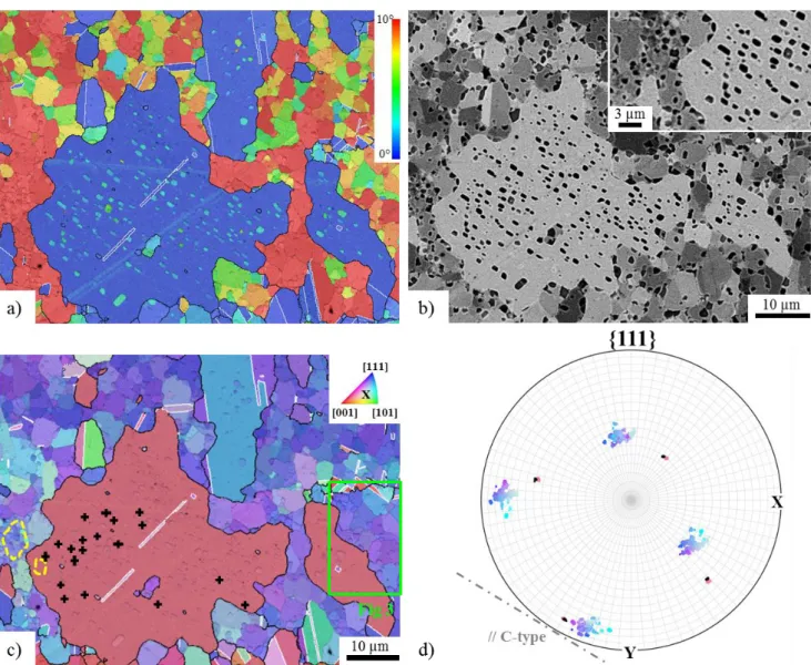
by calculating the average misorientation angle (𝜃̅) at the recrystallized/recovered boundary (average on 168
boundary segments of at least few tens of micrometers long). The values are summarized in Table 2. From Table 169
2, it can be noticed that recrystallized grains whose misorientation to the recovered grain is lower than ~37° 170
show C-type precipitates only. On the other hand, recrystallized grains which are misoriented by more than ~50° 171
show T-type precipitates only. Between these two misorientation angles, a transition zone is observed where 172
recrystallized grains exhibit both C and T type precipitates. So, although a more statistical analysis would be 173
required to obtain more precise transition values, there does exist a link between the misorientation angle of the 174
recrystallized grain relatively to the recovered grain and the precipitate type(s) which form(s). 175
176
To summarize, the C and T type precipitates are located in recrystallized grains which have grown into 177
recovered/substructured grains. Both can display rectangular shapes in sample sections. If so, the longest sides of 178
their rectangular shapes are up to a few micrometers in length and parallel to the trace of the {111} plane they 179
share with their host grain. The corresponding shared <111> axis is always very close to a <111> axis of the 180
consumed recovered/substructured grain. Thus, C and T type precipitates are both {111} bounded plate-like 181
particles which derive from the same mechanism. The misorientation angle between the recrystallized and the 182
recovered grains determines what precipitate type forms: while the less misoriented recrystallized grains only 183
display C-type precipitates, the highest misoriented recrystallized grains display only T-type precipitates, and 184
intermediate misorientations both types. Recrystallized grains with a <111> axis very close to one of the <111> 185
axes of the recovered grain they consume originate from the Continuous Recrystallization (CRX) and the 186
Heteroepitaxial Recrystallization (HERX) which are the two recrystallization mechanisms identified for the 187
recovered grains of the AD730TM alloy [18]. Both mechanisms produce recrystallized grains whose initial
188
orientations are close to that of the recovered grain. As the recrystallized grain grows into the recovered grain, its 189
misorientation with respect to the recovered grain increases because of the orientation gradients present inside 190
the recovered grain. By growing, the recrystallized grain may also undergo annealing twinning, so that the 191
misorientation of the recrystallization front changes from a rather low misorientation to a high one (or 192
conversely) due to the additional 60° <111> rotation. This explains why a wide range of misorientation angles is 193
observed at the recrystallized/recovered boundaries (Table 2). 194
195
B. Observations in other γ/γ’ superalloys: René65 and PER72 alloys
196
In René65 and PER72 billets, recovered grains with their characteristic high density of close-to-coherent 197
precipitates can also be observed (Fig.5.a and Fig.7.a). Besides, the configuration presented in Fig.1for the 198
AD730TM alloy is found in the René65 billet sample too (Fig.5): a few large recrystallized grains have grown to a
199
large extent inside a recovered grain. These large recrystallized grains are full of micrometric precipitates with 200
some of them well rectangular in the sample section (Fig.5.d-e). Some of the rectangular precipitates are in twin 201
orientation relationship to their host grain but the twin orientation relationship is imperfect because only realized 202
within the 8.66° tolerance given by Brandon’s criterion (Fig.6). Thus, such precipitates do correspond to the T-203
type precipitates as defined in the alloy AD730TM. In the same crystal, rectangular precipitates
slightly-204
misoriented to their surrounding matrix and parallel to the T-type precipitates are also found (Fig.5.d-e): these 205
precipitates are C-type precipitates. On the {111} pole figure (Fig.5.c), one can check that the crystal hosting the 206
T and C type precipitates has a <111> axis very close to a <111> axis of the recovered grain. Then, T and C type 207
precipitates are rotated around this common <111> axis with respect to their host grain and the corresponding 208
{111} plane trace coincides with the longest sides of their rectangular shapes. As observed in the AD730TM
209
alloy, the orientations of the two precipitate types are more homogeneous than that of the recovered grain. 210
Finally, CRX cells and HERX grains can be noticed at the borders of the recovered grain (black and white 211
arrows in Fig.5.a). 212
213
214
Fig.5 – C and T type precipitates resulting from the recrystallization of a recovered grain in the René65 alloy
215
(René65 billet sample). a) and b) EBSD map: orientation (IPF color code) overlaid on the band contrast map,
216
grain boundaries (misorientation angle threshold: 10°) plotted black and twin boundaries (60°<111> with 8.66°
217
tolerance) plotted white. In the inserts, the black and white arrows underline a CRX cell and a HERX grain
respectively. c) {111} pole figure on a spherical grid (spacing: 5°), orientations of the C-type precipitates (black
219
crosses in b)) plotted black, orientations of the T-type precipitates (green crosses in b)) plotted green and
220
orientations of the white selection in b) plotted with the same color as displayed in b). The {111} plane trace
221
common to the C/T type precipitates and the recrystallized matrix is displayed by a dashed line. d) EBSD map:
222
misorientation angle to the mean orientation of the grain overlaid on the band contrast map, grain boundaries
223
plotted black and twin boundaries plotted white. The black arrow underlines a T-type precipitate at the
224
recrystallization front. e) Backscattered electron image, where the γ’ precipitates appear bright despite their
225
lower atomic number because of topographic effects induced by electropolishing. C and T type precipitates are
226
highlighted by blue and red arrows respectively.
227 228 229
230
Fig.6 – The imperfect twin orientation relationship of the T-type precipitates (René65 billet sample). a) and b)
231
EBSD maps - misorientation angle to the mean orientation of the grain overlaid on the band contrast map, grain
232
boundaries (misorientation angle threshold: 10°) plotted black and twin boundaries (60°<111> with Δθ
233
tolerance) plotted white. In a) twin boundaries are plotted with 8.66° tolerance following Brandon’s criterion
234
[19]. In b) twin boundaries are plotted with 2° tolerance. c) {111} pole figure on a spherical grid (spacing: 5°).
235
The orientations of the T-type precipitates selected in a) are plotted green, the orientations of the surrounding
236
matrix and the corresponding perfect twin crystal (60°<111> 0° tolerance) are plotted purple and red
237
respectively.
238 239
No case of striking heterogeneous recrystallization with large recrystallized grains full of T/C type precipitates 240
has been observed in the studied PER72 billet sample. It is also worth mentioning here that, in the AD730TM and
241
René65 alloys, all the recovered grains do not always lead to several huge statically recrystallized grains as 242
shown throughout the paper. The reason why this phenomenon is not systematic is not understood yet but would 243
be interesting to investigate in future research. Nevertheless, in the PER72 alloy, isolated T and C type 244
precipitates are seen in recrystallized grains of “normal” size next to recovered grains (red and blue arrows in 245
Fig.7). For example, the yellow grain on Fig.7.a contains several C and T type precipitates. This grain has a 246
<111> axis not so far from a <111> axis of the nearby recovered grain (dashed circle in Fig.7.b), although it is 247
not the twin axis of the T-type precipitates. Some CRX cells and HERX grains are also seen in the recovered 248
grains of the PER72 alloy (white and yellow arrows in Fig.7). This means that the two recrystallization 249
mechanisms suspected in the AD730TM alloy as taking part to the formation of the T/C type precipitates also
250
occur in the PER72 alloy. 251
252
Fig.7 – A recovered grain in the PER72 alloy (PER72 billet sample). a) EBSD map: orientation (IPF color
253
code) overlaid on the band contrast map, grain boundaries (misorientation angle threshold: 10°) plotted black
254
and twin boundaries (60°<111> with 8.66° tolerance) plotted white. b) {111} pole figure on a spherical grid
255
(spacing: 5°), orientations of the C-type precipitates (black crosses in a)) plotted black, orientations of the
T-256
type precipitates (red crosses in a)) plotted green and orientations of the white selection in a) plotted with the
257
same color as displayed in a). A {111} plane trace is displayed by a dashed line. c) EBSD map: misorientation
258
angle to the mean orientation of the grain overlaid on the band contrast map, grain boundaries plotted black
259
and twin boundaries plotted white. d) Backscattered electron image, where the γ’ precipitates appear bright
260
despite their lower atomic number because of topographic effects induced by electropolishing. Red, blue, yellow
261
and white arrows highlight T-type precipitates, C-type precipitates, HERX grain and CRX cells respectively.
262 263
Thus, T and C type precipitates, with their characteristic {111} facets and orientation relationships, can be 264
identified in recrystallized grains near the recovered grains of the René65 and PER72 alloys. In the same way as 265
in the AD730TM alloy, the recrystallized host grain has a <111> axis very close to a <111> axis of the nearby
266
recovered grain. Such recrystallized grains are very likely to derive from the CRX and HERX which occur in the 267
recovered grains of the three alloys studied. 268
269 270
C. Clarification of the mechanism leading to T and C type precipitates
271
1. An advantageous mechanism to overcome a high density of close-to-coherent precipitates
272 273
Fig.8 displays several large recrystallized grains which have extensively grown by consuming the nearby 274
recovered grain. If the crystallographic orientations of these recrystallized grains (labelled by black stars in 275
Fig.8.a) are compared to those of the recovered grain (Fig.8.c), it appears that all the recrystallized grains – 276
except the grain N°1 in Fig.8.a – have a <111> axis close to a <111> axis of the recovered grain they consume 277
(less than 10° deviation). Moreover, all these large recrystallized grains show a high density of intragranular 278
precipitates which are C and/or T type precipitates (Fig.8.b). 279
On the other hand, many recrystallized grains attempting to consume a recovered grain remain very small (Fig. 280
9). If some of the small recrystallized grains can result from the CRX and HERX occurring in recovered grains, 281
many of them derive from Discontinuous Recrystallization (DRX) [22] and so have random orientations,
282
especially those at the periphery of the recovered grain. Nevertheless, whatever the origin of the small 283
recrystallized grains, each time the same pattern is noticed: i) recrystallized grains are small but larger than the 284
recovery cells of the recovered grain (which are delimited by close-to-coherent precipitates); ii) small 285
recrystallized grains are free from precipitates (except the precipitate which originated HERX); iii) some coarse 286
close-to-coherent precipitates can be pointed out on the boundaries of the small recrystallized grains. From this 287
pattern, a scenario explaining why these recrystallized grains remain so small may be developed. Given that 288
small recrystallized grains are always larger than recovery cells, they must start growing by dissolving the 289
nearby close-to-coherent precipitates. But, since no re-precipitation is observed behind the recrystallization front, 290
at first time all the γ’-forming elements remain stored in the moving boundary. Then, the high solute 291
concentration in the moving grain boundary decreases its mobility [22,23] and the boundary ends up stopping at
292
close-to-coherent precipitates. Finally, these close-to-coherent precipitates are fed by the γ’-forming elements 293
stored in the boundary and their coarsening leads to a high pinning force, which definitely prevents the boundary 294
from moving anymore. 295
The above observations suggest that the recrystallized grains having a <111> axis close to a <111> axis of a 296
recovered grain have an advantage over a randomly-oriented recrystallized grain in consuming it. Yet, 297
consuming a recovered grain amounts to overcoming the high Smith-Zener drag pressure exerted by its close-to-298
coherent precipitates. For spherical particles, the Smith-Zener drag pressure is usually described by the formula 299
𝑃𝑆𝑍 = Γ.3𝑓2𝑟 , where Γ, 𝑓 and 𝑟 are respectively the grain boundary energy, the precipitate volume fraction and the 300
precipitate mean radius [4]. In the present case, the drag pressure has not been precisely evaluated but, judging
301
from the precipitate density and size, it is very likely to be quite high. In addition, the intragranular precipitates 302
of the recovered grains are close-to-coherent and the drag pressure enforced by coherent precipitates is twice that 303
enforced by the equivalent incoherent population [8,9]. In literature several possible mechanisms to overcome
304
coherent precipitates have been pointed out: precipitates can be bypassed, dissolved (with a coherent re-305
precipitation behind the recrystallization front) [10,11] or crossed by the recrystallization front so that their
306
orientation is changed to that of the growing grain [7,8]. However here, none of these mechanisms is observed:
307
while many recrystallized grains stop growing very early inside the recovered grain, some recrystallized grains 308
sharing a <111> axis with the recovered grain can grow to a large extent producing T/C type precipitates. Thus, 309
the mechanism leading to T/C type precipitates appears as the more thermodynamically/kinetically interesting 310
mechanism to overcome the precipitates of the recovered grain. Yet, considering that T/C type precipitates are 311
bounded by {111} planes, this is consistent with a mechanism which minimize the energy of the system since 312
{111} planes are known to be low energy interfaces [24].
313
314
Fig.8 – Analysis of the heterogeneous recrystallization nearby a recovered grain (AD730TM Lab-Forged 315
sample). a) EBSD map: orientation map (IPF color code), grain boundaries (misorientation angle threshold:
316
10°) plotted black and twin boundaries (60°<111> with 8.66° tolerance) plotted white. b) EBSD map:
317
misorientation angle to the mean grain orientation overlaid on the band contrast map, grain boundaries plotted
318
black and twin boundaries plotted white. c) {111} pole figure on a spherical grid (spacing: 5°), orientations of
319
the recovered grain (white selection in a)) plotted black, orientations of the grains selected by black stars in a)
320
plotted with the same color they appear in a).
321 322
323
Fig.9 – Recrystallized grains unsuccessful in consuming the surrounding recovered grain (AD730TM Lab-Forged 324
sample). a) and c) Backscattered electron images, where the γ’ precipitates appear bright despite their lower
325
atomic number because of topographic effects induced by electropolishing. b) and d) EBSD map: orientation
326
(IPF color code) overlaid on the band contrast maps, grain boundaries (misorientation angle threshold: 10°)
327
plotted black and twin boundaries (60°<111> with 8.66° tolerance) plotted white.
328 329 330
2. Involving grain boundary faceting
331 332
As highlighted in [18], the few T-type precipitates evidenced at the recrystallization front (black arrows in Fig.5,
333
Fig.10 and Fig.11) prove that T-type precipitates form at the recrystallization front with their characteristic 334
orientation and facetted shape. Similarly, a C-type precipitate is seen at the recrystallization front in Fig.12.k 335
(black cross). 336
337
338
Fig.10 – A T-type precipitate at the recrystallization front in the AD730TM alloy (AD730TM Lab-Forged sample). 339
a) Backscattered electron image, where the γ’ precipitates appear bright despite their lower atomic number
340
because of topographic effects induced by electropolishing. b) EBSD map: misorientation angle to the mean
341
orientation of the grain overlaid on the band contrast map, grain boundaries (misorientation angle threshold:
342
10°) plotted black and twin boundaries (60°<111> with 8.66° tolerance) plotted white. The black arrow
343
underlines a T-type precipitate at the recrystallization front. c) EBSD map: orientation (IPF color code)
344
overlaid on the band contrast map, grain boundaries plotted black and twin boundaries plotted white. d) {111}
345
pole figure on a spherical grid (spacing: 5°), orientations of the red selection in c) plotted with the same color as
346
displayed in c). The {111} plane trace common to the T-type precipitate and the selected matrix is displayed by a
347
dashed line.
348 349
350
351
Fig.11 – A T-type precipitate at the recrystallization front in the René65 alloy (René65 billet sample). a)
352
Backscattered electron image, where the γ’ precipitates appear bright despite their lower atomic number
353
because of topographic effects induced by electropolishing. The white arrow highlights a grain boundary facet.
354
b) EBSD map: misorientation angle to the mean orientation of the grain overlaid on the band contrast map,
355
grain boundaries (misorientation angle threshold: 10°) plotted black and twin boundaries (60°<111> with 8.66°
356
tolerance) plotted white. The black arrow underlines a T-type precipitate at the recrystallization front. c) EBSD
357
map: orientation overlaid on the band contrast map, grain boundaries plotted black and twin boundaries plotted
358
white. d) {111} pole figure on a spherical grid (spacing: 5°), orientations of the red selection in c) plotted with
359
the same color as displayed in c), orientation of the selected T-type precipitate (green cross in c)) plotted green.
360
The {111} plane trace common to the recrystallized and recovered grains is displayed by a dashed line.
361 362 363
364
Fig.12 – {111} grain boundary facets at the recrystallization front (AD730TM billet sample). 1st column (a, e and 365
i): Backscattered electron images. Secondary electron image inserted in e), the red arrows point out a twin
366
boundary inside a precipitate. 2nd column (b, f and j): EBSD maps - misorientation angle to the mean 367
orientation of the grain overlaid on the band contrast maps, grain boundaries (misorientation angle threshold:
368
10°) plotted black and twin boundaries (60°<111> with 8.66° tolerance) plotted white. 3rd column (c, g and k): 369
EBSD maps - orientation (IPF color code) overlaid on the band contrast maps, grain boundaries plotted black
370
and twin boundaries plotted white. The white arrows highlight grain boundary facets. 4th column (d, h and l): 371
{111} pole figures on a spherical grid (spacing: 5°), orientations of the recrystallized/recovered interface plotted
372
with the same color as displayed in the orientation maps, orientations of the selected C-type precipitates (black
373
crosses) plotted black. Some {111} plane traces, parallel to grain boundary facets, are displayed by dashed
374
lines.
375 376
In the AD730TM billet sample, small facets in the range of 0.5 to 2 µm wide can be observed on the
377
recrystallized/recovered front (Fig.12). Most of the facets coincide with a {111} plane trace the recrystallized 378
and recovered grains have in common (white arrows on the orientation maps Fig.12). On these facets, 379
precipitates large, facetted and slightly misoriented compared to the neighboring recovered matrix are implanted 380
(misorientation angle to the mean grain orientation maps Fig.12). The insert in Fig.12.e even shows, inside a 381
precipitate implanted on a recrystallization front facet, a twin boundary being itself parallel to the 382
recrystallization front facet. Similarly, in the René65 alloy, the T-type precipitate visible at the recrystallization 383
front is implanted on a facet which lies on a {111} plane the recrystallized and recovered grains have in common 384
(white arrow in Fig.11.a). 385
386
The {111} facets of the T/C type precipitates are very unusual for γ’ precipitates since coherent {100} cuboidal 387
γ’ precipitates are classically observed in nickel-based superalloys [20,25,26]. Yet, γ’ precipitates always evolve so
388
as to minimize the system free energy. For instance, the classical {100} cuboidal shape allows the minimization 389
of the elastic strain energy occurring at the coherent interfaces due to the γ-γ’ lattice mismatch. For C/T 390
precipitates, the elastic strain energy is small since their imperfect cube-cube/twin orientation relationships 391
require interfacial dislocations to accommodate the elastic strain. Thus, the morphology and orientations of the 392
C/T type precipitates are mainly controlled by their interfacial energy which has to be minimized considering the 393
recrystallized and recovered sides since C/T type precipitates form at the recrystallization front. 394
The recrystallized and recovered grains share a <111> axis. Yet, <111>twist boundaries have a much lower 395
boundary energies than any other grain boundary type, with minima at 0°<111> and 60°<111> corresponding to 396
the cube-cube and twin orientation relationships respectively (from [24] the energy of a <111>twist boundary does
397
not exceed 0.5 J/m² while a random boundary can reach 1.5 J/m²). Thus, by developing <111>twist boundaries 398
(approximately) lying on the {111} plane common to the recovered and recrystallized grains, the precipitates 399
decrease their interfacial energy on both recovered and recrystallized sides. Finally, the γ/γ’ <111>twist rotation 400
angle which is adopted is the best compromise to minimize the total interfacial energy of the precipitate. This 401
rotation angle is logically close to 0° or 60°, depending on the mutual misorientation of the recrystallized and 402
recovered grains. 403
Regarding the formation of the {111} facets which have been noticed at the recrystallization front, two 404
hypotheses can be considered; they are schematically represented in Fig.13. The first one (H1) is that the 405
recrystallization front naturally tends to develop {111} facets, and thus <111>twist portions, because of the 406
<111> axis its shares with the recovered grain. Then, due to the supersaturation of the recrystallization front, γ’-407
forming elements re-precipitate on these {111} facets in order to minimize the total interfacial energy of the 408
obtained precipitates as just explained above. Coincidence Site Lattice (CSL) boundaries naturally tend to facet 409
and the obtained facets are preferentially the crystallographic planes densely packed with coincidence sites [27,28].
410
Many CSL boundaries in the FCC structure are equivalent to a <111> rotation and so present the {111} planes as 411
densely packed CSL planes. The names of these CSL boundaries as well as their corresponding rotation angle 412
are given in Table 3. One can notice that the <111> rotation angles of these CSL boundaries cover the whole 413
recrystallized/recovered misorientation angle range presented in the present paper (Table 2). 414
In the second hypothesis (H2), the T/C type precipitates first nucleate at an initially rough recrystallization front 415
due to solute supersaturation. This nucleus is <111> rotated with respect to the recrystallized and recovered 416
grains so as to minimize its interfacial energy. Then, while growing, the precipitate develops its characteristic 417
{111} facets to again minimize its interfacial energy. The γ/γ’ {111} facets of the precipitate oblige the 418
recrystallization front in turn to facet so as to bypass it. 419
At the moment, given the available information, deciding which hypothesis between H1 and H2 is the most 420
likely is not possible. But, whatever the hypothesis considered, as the T/C type precipitates form at the 421
recrystallization front but inside the recovered grain, the recrystallization front still has to bypass them to carry 422
on growing. Because T and C type precipitates are {111} bounded plate-like particles, the classical Smith-Zener 423
model which is used for spherical particles and, above all, which ignores the interfacial energies between the 424
grains and the particle is not the most appropriate here. However, the work of Ringer et al. [29] on grain boundary
425
pinning by stable cubic-shaped particles is interesting to consider. Indeed, they highlighted that the pinning 426
enforced by a cubic or spherical particle strongly depends the “degree of particle coherency” defined by the 427 ratio: 428 𝐷𝑃𝐶= Γ1𝑝−Γ2𝑝 Γ12 429
Where the grain 1 is non-recrystallized, the grain 2 is recrystallized, Γ𝑖𝑝 is the energy of the graini/particle 430
interface and Γ12 is the grain boundary energy. Ringer et al. evidenced that for a cubic (or spherical) particle the 431
pinning force is minimal for low 𝐷𝑃𝐶 values. On the contrary, in case of a coherent particle, the 𝐷𝑃𝐶 is close to 1 432
and the pinning force is much higher. As said above, <111>twist interfaces have low energy values. Thus, 433
considering the T/C type precipitates delimited by <111> twist boundaries whose corresponding {111} plane is 434
common to the recrystallized and recovered grains, Γ1𝑝 and Γ2𝑝 are very low compared to Γ12, so the 𝐷𝑃𝐶 is small 435
and the pinning enforced is minimized. 436
437
Fig.13 – Schematic diagrams describing the two hypotheses (H1 and H2) for the formation of {111} facets at the
438
recrystallized/recovered front.
439 440
3. Scenario proposed for the formation of C and T type precipitates
441 442
At this point, a scenario for the formation of T and C type precipitates can be proposed. Under hot-deformation 443
and subsequent heat-treatments, recovered grains partially recrystallize by forming CRX and HERX grains 444
which are low-misoriented to the surrounding recovered matrix. Recrystallized grains are also produced by DRX 445
occurring at the periphery of the recovered grain as everywhere in the equiaxed grain areas. During an annealing 446
stage, all these recrystallized grains start growing inside the recovered grain due to its relatively high stored 447
energy. This first growth step is supported by the dissolution of the precipitates encountered in the recovered 448
grain, so that the recrystallization front gets more and more saturated with γ’-forming elements. Then, there are 449
two cases. In the first case, the recrystallization front gets so saturated that the high solute concentration 450
decreases significantly its mobility. Thus, the recrystallization front stops at some precipitates of the recovered 451
grain and the γ’-forming elements stored in the front feed those precipitates. Those precipitates coarsen, pin and 452
prevent the boundary from further motion. The second case concerns the recrystallized grains sharing a <111> 453
axis with the nearby recovered grain. These recrystallized grains mainly derive from the CRX and HERX 454
occurring in the recovered grain. The common <111> axis can allow: H1) the formation on the recrystallization 455
front of facets lying on the {111} common planes, then the implantation of γ’-forming elements on the {111} 456
facets as a consequence of supersaturation; H2) the formation of precipitates facetted by the {111} common 457
planes on a rough recrystallization front due to supersaturation, this then obliges the recrystallization front to 458
form {111} facet in order to bypass them. Whatever the hypothesis (H1 or H2), what is sure is that the T/C type 459
precipitates form inside the recovered grain at the recrystallization front, and develop these {111} facets 460
combined with specific orientations to minimize their interfacial energy including both the recrystallized and 461
recovered sides. Indeed, <111>twist boundaries have low energies with minima at 60°<111> and 0°<111>. This 462
implies that the lowest misoriented recrystallized grains (< ~37°) lead to precipitates implanted approximately at 463
0°<111> on the front, the highest misoriented ones (> ~50°) lead to precipitates implanted approximately at 464
60°<111> on the front, and that for the intermediate misorientations both implantations are possible. The low 465
interfacial energies on both recrystallized and recovered sides make the facetted precipitates little costly to 466
bypass. The obtained precipitates are few degrees rotated to their host recrystallized grain (~0°<111> - C-type) 467
or in close-to-twin orientation relationship (~60°<111> - T-type). Released from the γ’ elements it contained, the 468
recrystallization front can carry on moving inside the recovered grain and repeat the same mechanism. 469
Nevertheless, the scenario which is proposed here has some weaknesses. First, the reason why all the grains 470
derived from the CRX and HERX in the recovered grain do not succeed in growing to a large extent inside the 471
recovered grain is not understood yet. Thus, the mechanism leading to T/C type precipitates must require 472
additional conditions to a common <111> axis to happen. Second, the reason why the γ’ precipitates re-arrange 473
inside the recovered grain and not coherently behind the recrystallization front as it is expected from the 474
literature is unclear too. One can imagine that the γ’-forming elements precipitate around a precipitate pre-475
existing in the recovered grain with a slight change in orientation to minimize the interfacial energy. However, 476
no such sub-boundary has been observed into the T/C type precipitates yet. Another reason which could account 477
for this is the enhanced γ’-forming element diffusion which occurs in the recovered grain due its highly 478
developed network of dislocations [30]. All these points need to be clarified in future research.
479 480
IV.
CONCLUSION
481
A previous work [18] has pointed out a close-to-twin orientation relationship between micrometric γ’ precipitates
482
and their host recrystallized grain in the AD730TM γ-γ’ nickel-based superalloy. The aim of the present paper is
483
to clarify the mechanism leading to such precipitates called T-type precipitates. 484
This paper shows that: 485
1. The mechanism leading to T-type precipitates is also able to form C-type precipitates, which are 486
micrometric γ’ precipitates slightly misoriented to their surrounding matrix by a rotation of few degrees 487
around a <111> axis. Both C and T type precipitates are found in recrystallized grains which have 488
grown into a recovered grain and which (approximately) share a <111> axis with this recovered grain. 489
The recrystallized grains sharing a <111> axis with a recovered grain derive from the CRX and HERX 490
occurring in the recovered grain. 491
2. The misorientation angle between the recrystallized and recovered grains determines if the precipitates 492
are mainly C-type (< ~37°), mainly T-type (> ~50°) or both (between ~37 and ~50°). 493
3. Both C and T type precipitates are facetted by {111} planes whose corresponding <111> axes are 494
common to the T/C type precipitates, the surrounding recrystallized matrix and the consumed recovered 495
grain. 496
4. Like the AD730TM alloy, the René65 and PER72 alloys can exhibit large recovered grains. In the
497
René65 and PER72, T and C type precipitates with their characteristic shape and orientation 498
relationships are found in recrystallized grains sharing a <111> axis with the nearby recovered grain. 499
Those recrystallized grains derive from the CRX and HERX mechanisms which have been also pointed 500
out in the recovered grains of the René65 and PER72 alloys. So, the mechanism leading to T/C type 501
precipitates may possibly occur in all the low-lattice-mismatch γ-γ’ nickel-based superalloys. 502
5. The mechanism leading to T/C type precipitates is an advantageous mechanism to overcome the high 503
density of close-to-coherent precipitates in a recovered grain. Thus, regarding a random recrystallized 504
grain, recrystallized grains derived from the CRX and HERX occurring in the recovered grain are 505
privileged for consuming it. 506
6. T/C type precipitates appear in the recovered grain at the recrystallization front. They grow onto {111} 507
facets that the recrystallization front developed due to its crystallographic structure (H1), or grow 508
directly with {111} facets on a rough recrystallized front which is then obliged to form {111} facets in 509
order to bypass them (H2). Whatever the hypothesis, T/C type precipitates develop <111>twist 510
boundaries with specific rotation angles (~60°<111> and ~0°<111>) in order to minimize their 511
interfacial energy including both the recovered and recrystallized sides. Then, the low interfacial energy 512
on both the recrystallized and recovered sides of the T/C precipitates makes them little costly to bypass. 513
7. However, some points of the suggested scenario remain unclear. First, as all the CRX and HERX grains 514
formed from the recovered grain do not display T/C type precipitates, additional conditions must 515
certainly be required for the mechanism to happen. Second, the re-precipitation in the recovered grain 516
and not in the recrystallized grain as it is expected from the literature may be perhaps due to the 517
enhanced diffusion occurring in the recovered grain because of its network of dislocations. 518
ACKNOWLEDGMENTS
519 520
This work has been carried out thanks to the financial support of the ANR-Safran industrial chair OPALE. 521
522
REFERENCES
523
1 D. Furrer and H. Fecht: JOM, 1999, vol. 51, pp. 14–7. 524
525
2 R.C. Reed: The Superalloys, Fundamentals and Applications, Cambridge University Press, 2006. 526
527
3 R.W. Kozar, A. Suzuki, W.W. Milligan, J.J. Schirra, M.F. Savage, and T.M. Pollock: Metall. Mater. 528
Trans. A, 2009, vol. 40, pp. 1588–603.
529 530
4 P.A. Manohar and F. Chandra: ISIJ Int., 1998, vol. 38, pp. 913–24. 531
532
5 F.C. Campbell: Elements of Metallurgy and Engineering Alloys, ASM Intern., 2008. 533
534
6 G.S. Rohrer: J. Mater. Sci., 2011, pp. 5881–95. 535
536
7 V. Randle and B. Ralph: Acta Metall., 1986, vol. 34, pp. 891–8. 537
538
8 R.D. Doherty: Met. Sci., 1982, vol. 16, pp. 1–13. 539
540
9 E. Nes, N. Ryum, and O. Hunderi: Acta Metall., 1985, vol. 33, pp. 11–22. 541
542
10 R.W. Cahn and P. Haasen: Physical Metallurgy, Volume I, North Holland, 1996. 543
544
11 A. Porter and B. Ralph: J. Mater. Sci., 1981, vol. 16, pp. 707–13. 545
546
12 M.A. Charpagne, P. Vennéguès, T. Billot, J.M. Franchet, and N. Bozzolo: J. Microsc., 2016, vol. 263, 547
pp. 106–12. 548
549
13 M. Charpagne, T. Billot, J. Franchet, and N. Bozzolo: Superalloys 2016, 2016, pp. 417–26. 550
551
14 M.A. Charpagne, T. Billot, J.M. Franchet, and N. Bozzolo: J. Alloys Compd., 2016, vol. 688, pp. 685– 552
94. 553
554
15 B.J. Bond, C.M.O. Brien, J.L. Russell, J.A. Heaney, and M.L. Lasonde: 8th Int. Symp. Superalloy 718 555
Deriv., 2014, pp. 107–18.
556 557
16 R.S. Minisandram, L.A. Jackman, J.L. Russell, M.L. Lasonde, J.A. Heaney, and A.M. Powell: 8th Int. 558
Symp. Superalloy 718 Deriv., 2014, pp. 95–105.
559 560
17 C. Crozet, A. Devaux, R. Forestier, S. Charmond, M. Hueller, D. Helm, and W. Buchmann: Superalloys 561
2016 Proc. 13th Int. Symp. Superalloys, 2016, pp. 437–46.
562 563
18 S. Vernier, J.-M. Franchet, C. Dumont, P. Vennéguès, and N. Bozzolo: Scr. Mater., 2018, vol. 153, pp. 564
10–3. 565
566
19 D.G. Brandon: Acta Metall., 1966, vol. 14, pp. 1479–84. 567
568
20 R.A. Ricks, A.J. Porter, and R.C. Ecob: Acta Metall., 1983, vol. 31, pp. 43–53. 569
570
21 G. Nolze and R. Hielscher: J. Appl. Crystallogr., 2016, vol. 49, pp. 1786–802. 571
572
22 J. Humphreys, G.S. Rohrer, and A. Rollett: Recrystallization and Related Annealing Phenomena, 3rd 573
edn., Elsevier Ltd, 2017. 574
23 Y. Huang and F.J. Humphreys: Mater. Chem. Phys., 2012, vol. 132, pp. 166–74. 576
577
24 D.L. Olmsted, S.M. Foiles, and E.A. Holm: Acta Mater., 2009, vol. 57, pp. 3694–703. 578
579
25 A.G. Khachaturyan, S. V. Semenovskaya, and J.W. Morris: Acta Metall., 1988, vol. 36, pp. 1563–72. 580
581
26 S.J. Yeom, D.Y. Yoon, and M.F. Henry: Metall. Mater. Trans. A, 1993, vol. 24A, pp. 1975–81. 582
583
27 B.B. Straumal, O.A. Kogtenkova, A.S. Gornakova, V.G. Sursaeva, and B. Baretzky: J. Mater. Sci., 2015, 584
vol. 51, pp. 382–404. 585
586
28 B.B. Straumal, S.A. Polyakov, E. Bischoff, W. Gust, and E.J. Mittemeijer: Interface Sci., 2001, vol. 9, 587
pp. 287–92. 588
589
29 S.P. Ringer, W.B. Li, and K.E. Easterling: Acta Metall., 1989, vol. 37, pp. 831–41. 590
591
30 R.W. Balluffi: Phys. Status Solidi, 1970, vol. 11, pp. 11–34. 592
593
31 A. Devaux, B. Picqué, M.F. Gervais, E. Georges, T. Poulain, and P. Héritier: Superalloys 2012, 2012, 594
pp. 911–9. 595
596
32 H. Grimmer, W. Bollmann, and D.H. Warrington: Acta Crystallogr. Sect. A, 1974, vol. 30, pp. 197–207. 597
598
TABLES
599 600
Table 1 – Chemical compositions of the alloys used in the present work (wt. %)
601 Element Ni Fe Co Cr Mo W Al Ti Nb B C Zr AD730TM [31] Bal. 4.00 8.50 15.70 3.10 2.70 2.25 3.40 1.10 0.01 0.015 0.03 René65 [15] Bal. 1 13 16 4 4 2.1 3.7 0.7 0.016 - 0.05 PER72 Bal. 0.138 14.5 16.06 2.88 1.21 2.57 5.07 - 0.016 0.017 - 602 603 604 605 606 607 608 609 610 611 612 613 614 615 616 617 618 619 620 621 622
Table 2 – Average misorientation angle 𝜃̅ calculated at recrystallized/recovered grain boundaries
623
𝜽̅ at grain boundary Precipitate Type REX Grain reference
23.2° C Purple crystal in Fig.4.c
24.2° C Grain N°2 in Fig.8.a
25.2° C + 1 single T Red grain in Fig.2.c
29.7° C Grain N°4 in Fig.8.a
31.8° C Grain N°6 in Fig.8.a
32.4° C Grain N°7 in Fig.8.a
36.3° C Orange grain in Fig.12.c
37.7° C + T Grain N°5 in Fig.8.a
47.9° C + T Purple grain in Fig.5.b
53.2° T Orange twin crystals in Fig.4.c
53.8° T Green grain in Fig.10.c
624 625
Table 3 – CSL boundaries equivalent to a <111> rotation in a FCC structure [32]
626
CSL boundary Rotation axis Rotation angle
Σ3 <111> 60° Σ7 <111> 38.21° Σ13b <111> 27.79° Σ19b <111> 46.82° Σ21a <111> 21.78° Σ31a <111> 17.9° Σ37c <111> 50.57° Σ39a <111> 32.2° Σ43a <111> 15.18° Σ49a <111> 43.57° 627
![Table 1 – Chemical compositions of the alloys used in the present work (wt. %) 601 Element Ni Fe Co Cr Mo W Al Ti Nb B C Zr AD730 TM [31] Bal](https://thumb-eu.123doks.com/thumbv2/123doknet/11647317.307991/22.892.57.795.69.1214/table-chemical-compositions-alloys-used-present-work-element.webp)