HAL Id: tel-00807094
https://tel.archives-ouvertes.fr/tel-00807094
Submitted on 3 Apr 2013HAL is a multi-disciplinary open access
archive for the deposit and dissemination of sci-entific research documents, whether they are pub-lished or not. The documents may come from teaching and research institutions in France or abroad, or from public or private research centers.
L’archive ouverte pluridisciplinaire HAL, est destinée au dépôt et à la diffusion de documents scientifiques de niveau recherche, publiés ou non, émanant des établissements d’enseignement et de recherche français ou étrangers, des laboratoires publics ou privés.
Control of humanoid robots to realize haptic tasks in
collaboration with a human operator
Paul Evrard
To cite this version:
Paul Evrard. Control of humanoid robots to realize haptic tasks in collaboration with a human operator. Robotics [cs.RO]. Université Montpellier II - Sciences et Techniques du Languedoc, 2009. English. �tel-00807094�
No d’ordre: xxxx
THÈSE
présentéedevant l’Université de Montpellier 2
pour obtenir
le grade de : DOCTEUR DE L’UNIVERSITÉ DEMONTPELLIER2
Mention SYSTÈMESAUTOMATIQUES ET MICROÉLECTRONIQUES
par
Paul EVRARD
Laboratoire d’accueil : CNRS-AIST JRL, UMI3218/CRT École Doctorale : Information, Structures, Systèmes
Titre de la thèse :
Contrôle d’humanoïdes pour réaliser
des tâches haptiques en coopération
avec un opérateur humain
Soutenance prévue le 07/12/2009 devant la commission d’examen
Étienne BURDET Rapporteurs
Alain MICAELLI
Aude BILLARD Examinateurs
Martin BUSS
André CROSNIER
Konstantinos TZAFESTAS
Kazuhito YOKOI
Abstract
H
APTICcollaborative tasks are actions performed jointly by several partners,involving direct or indirect physical contact among them. A typical example of such tasks are collaborative manipulation tasks, where the partners apply forces on a same object to impose it a desired motion or bring it to a target location. Human beings learn naturally how to perform such tasks with other human partners, but implementing such behaviors on a robotic platform is challenging. When jointly manipulating an object, the partners no longer act independently, and must negoti-ate a common planto perform the task.
To avoid conflicts among the partners’ intentions, the leader-follower model defines a task leader, who imposes a task plan to the other partners, while the latter act as follower and follow at best the intentions of the leader. This model has often been used in physical Human-Robot Interaction (pHRI). Because robotic systems have limited cognitive capabilities in comparison to human beings, a follower role has generally been assigned to robotic systems to cooperate with human operators. Recently, thanks to the increasing computational power embedded into the robots, more and more initiative has been given to robotic assistants. In some recent works, robots were sometimes even given the possibility to lead human operators.
In the context of physical tasks, where the partners are in direct or indirect contact through an object and exchange mechanical energy, we believe that the haptic channel is a favored and fast way for the partners to exchange information about their intentions. Therefore, this thesis will focus on the kinesthetic aspects of collaborative tasks. The long-term aim of the project is to endow humanoid robots with the necessary haptic skills to perform collaborative tasks with a human operator as a partner rather than as a helper. The work presented here proposes solutions towards this direction.
In its first part, our contribution is to extend the leader-follower model to con-tinuous, time-varying role distributionsamong the partners in the context of haptic dyadic collaborative tasks. This model describes the behavior of each partner of the dyad as a variable weighting between the two extreme leader and follower behaviors. Our goal is to abstract the concept of role distribution from the im-plementation of the underlying controllers, and to describe the behavior of dyads using two independent functions that will shape the behavior of each partner in term of leadership. We exemplify the use of our model in a virtual reality scenario where a human operator manipulates an object in cooperation with a virtual robotic system. We also explore possible strategies to exploit it. The problem we adress is to define how the weighting between both behaviors can be adjusted automati-cally on a robotic system, depending on various criteria such as constraints of the robot or knowledge from human-human haptic interaction. Simulations and ex-periments conducted on a humanoid robot are presented to illustrate the proposed solutions. The results show that the extended leader-follower model can be applied to realize collaborative tasks with a human operator while avoiding self-collision. The model also encompasses the specialization phenomenon recently highlighted in human-human collaborative haptic tasks.
col-laborative skills to a robotic system. This method uses a probabilistic framework to encode the characteristics of the task and reproduce it autonomously. This frame-work is based on Gaussian Mixture Models and Gaussian Mixture Regression and has been successfully applied to various stand-alone tasks. We remind the main components of this framework and present its application to collaborative lifting tasks between a humanoid robot and a human operator. Our first contribution is the design of the experimental setup, based on a teleoperation system whith kinesthetic feedback which allows the human teacher to demonstrate the task while taking into account the constraints and sensor data of the robotic system. The main contribu-tion, however, is the use of this methodology to attempt to assess the validity of our extended leader-follower model, by highlighting smooth switching behaviors on human partners during collaborative lifting tasks. The experimental data aquired during reproductions of the task is analyzed within this perspective.
The second part of this thesis focuses on the control of humanoid robots in the context of pHRI. We examine several paradigms of interaction: interaction be-tween two remote human partners through a tele-presence system, direct interac-tion between an autonomous humanoid robot and a human operator, and collabora-tive transportation tasks between a human operator and a humanoid robot. Behind these different paradigms of interaction lies one common problem: the generation of whole-body motion and gait in response to external forces that arise from the haptic interaction with a human operator. This thesis does not aim at tackling the problem of gait generation at the mechanical and control level. We will rather use state-of-the-art algorithms which do not consider external disturbances, and show to what extent they can be used to generate complex and intuitive collaborative behaviors. Our contributions in this part are thus to integrate impedance control and gait generation within an existing control architecture in a generic and flexible way in order to (i) use the resulting controller in various contexts, (ii) demonstrate how the basic principles of impedance control can be implemented on a complex platform biped humanoid robotwhile exploiting all the capabilities of such plat-forms and (iii), highlight the limitations of the passivity-based approaches often used in pHRI, and thereby justify further research in the field of pHRI. The work presented in this part has been integrated within a complex demonstrator where the robot walks in a teleoperated manner and performs autonomously a collaborative transportation task with a human operator.
Acknowledgements
T
HE works presented here have been conducted in the CNRS-AIST JointRobotics Laboratory, in Tsukuba, Japan. I would like to thank my supervisor Abderrahmane Kheddar, for having offered me such a fantastic opportunity. I am grateful for all the help and support he provided me, and for the knowledge and know-how I gained through these three years.
I thank Etienne Burdet and Alain Micaelli as well as all members of the committee for accepting to review this thesis, for attending my defence, and for the helpful comments.
I would like to thank Kazuhito Yokoi and Eiichi Yoshida for welcoming me in their laboratory, and for their precious help with Japanese administration. For all the help in Japanese I thank Tokiko Uga, Jean-Rémy Chardonnet, Hitoshi Arisumi and Makoto Yamaguchi. My Ph.D. student life in Japan would not have been as confortable without their priceless assistance.
Special thanks to Aude Billard, Martin Buss, Sylvain Calinon, Satoshi Endo, Elena Gribovskaya, Sandra Hirche, Inga Krause, Angelika Peer, Thomas Schauss and Carolina Weber for their collaboration within the European projects Robot@CWE and ImmerSence.
For the time spent with our favorite robot, all the discussions, his friendship and his role in one of the most important events of my life, I deeply thank Olivier Stasse. I would also like to express my special thoughts towards François Keith, for being such a trustworthy friend, collaborator, and coding buddy.
Special thoughts also to Diane Larlus for helping me improve my typing ability and for dealing with a couple of LaTeX issues; special thoughts, and con-gratulations to Nicolas Mansard, who managed to convince me to practice some sports despite my busy schedule.
Many thanks to Audrey Imbert, Sebastien Lengagne, Claire Dune, François Maillard and Anthony David for their assistance when moving back to France. Many thanks also to all the people who made this stay in Japan so enriching.
Last, but not least, I would like to express my deepest love and gratitude to my wonderful wife, who supported me through these years. There can be no bad day as long as I know I am seeing her when going back home.
Contents
Abstract i
Contents v
List of Figures ix
List of Tables xvi
1 Haptic interaction: a survey 1
1.1 Introduction . . . 3
1.1.1 Humanoid robots . . . 3
1.1.2 Haptic collaborative tasks. . . 3
1.1.3 Interaction control and the leader-follower model . . . 5
1.1.4 Human-human collaboration . . . 5
1.2 Impedance control . . . 7
1.2.1 Force control and compliance control . . . 7
1.2.2 Impedance control . . . 8
1.2.3 Contact instability . . . 14
1.2.4 Conclusion . . . 15
1.3 Impedance control and collaborative tasks . . . 15
1.3.1 Why impedance control? . . . 16
1.3.2 Applications in the previous works . . . 17
1.3.3 Limitations . . . 19
1.3.4 Conclusion . . . 21
1.4 Recent advances: towards perfect followers? . . . 22
1.4.1 Human impedance models . . . 22
1.4.2 Active following . . . 23
1.4.3 Proactive behaviors . . . 25
1.4.4 Leader robots? . . . 25
1.4.5 Conclusion . . . 26
1.5 Conclusion . . . 26
2 Physical collaborative tasks: a homotopy-based interaction model 29 2.1 A homotopy switching model for physical Human-Robot Interaction 31 2.1.1 The leader-follower model . . . 31
2.1.2 Intuition . . . 31
2.1.3 Mathematical formulation . . . 32
2.1.4 Example: linear homotopy . . . 33
2.1.5 Genericity of the proposed model . . . 34
2.1.6 Challenges for the application to pHRI: reasons for a haptic lan-guage . . . 35
2.1.7 Relation to previous works . . . 36
2.1.8 Behavioral architecture . . . 37
2.2 A concrete example . . . 38
2.2.1 Setup . . . 39
2.2.2 Results. . . 40
2.2.3 Extension to a Person-Object-Avatar scenario . . . 41
2.3 Defining the homotopy . . . 44
2.3.1 Enforcing constraints: self-collision avoidance. . . 45
2.3.2 parameterizing phenomena observed in human-human collabo-ration . . . 47
2.3.3 Conclusion . . . 52
2.4 Conclusion . . . 52
3 Learning haptic patterns 55 3.1 Programming by demonstration of collaborative tasks . . . 57
3.1.1 Introduction . . . 57
3.1.2 Programming by Demonstration . . . 58
3.1.3 Application to Human-Robot collaborative lifting tasks . . . . 59
3.2 Demonstration setup and experiments . . . 59
3.2.1 Hardware setup and controller . . . 60
3.2.2 Experiments . . . 62
3.2.3 Conslusions . . . 62
3.3 Learning collaborative tasks . . . 64
3.3.1 Probabilistic encoding of the task . . . 65
3.3.2 Probabilistic reconstruction of the task . . . 66
3.3.3 Control scheme. . . 68 3.4 Task reproduction . . . 70 3.4.1 Reproduction setup . . . 70 3.4.2 Preliminary analysis . . . 70 3.4.3 Quantitative analysis . . . 73 3.5 Conclusion . . . 79
4 Collaborative tasks via telepresence 81 4.1 Teleoperation of humanoid robots: a brief review . . . 83
4.2 The telepresence setup . . . 84
4.3 Taxonomies of coupling . . . 85
4.4 Whole-body control and extension to wide-area motions . . . 87
4.4.1 Whole-body motion control . . . 88
4.4.2 Force-based control. . . 89
4.4.3 Wide-area motions . . . 90
4.5 Experiments . . . 90
4.5.1 Setup . . . 90
4.5.2 Control . . . 91
4.5.3 Results and Discussion . . . 93
4.6 Conclusion . . . 96
5 Experiments on virtual avatars and humanoid robots 99 5.1 Introduction . . . 101
5.2 Collaborative transportation task . . . 102
5.2.1 Problem statement . . . 102
5.2.2 Stack of Tasks . . . 103 vi
5.2.3 Force-based control . . . 103
5.2.4 Real-time Walking Pattern Generator . . . 105
5.2.5 Footprints planning: the Mobile Robot Helper approach . . . . 106
5.2.6 Decoupling the gait and manipulation tasks . . . 108
5.3 Integration and implementation . . . 111
5.3.1 Software framework . . . 111
5.3.2 Integration . . . 114
5.3.3 Implementation issues . . . 114
5.3.4 Experimental results . . . 116
5.3.5 Integration to the final demonstrator of the Robot@CWE project 118 5.3.6 Discussion and future works . . . 121
5.4 Conclusion . . . 122
A Bilateral coupling of the end-effectors for a tele-cooperation system129 A.1 Network model . . . 129
A.1.1 Modelling the operator and environment. . . 129
A.1.2 Adding a second human in the loop . . . 129
A.1.3 Teleoperation interface and communication setup . . . 130
A.2 Stability analysis . . . 131
A.2.1 Model . . . 131
A.2.2 Stability criterion . . . 131
A.2.3 Numerical analysis . . . 133
B A study of inter-trial adaptation in dyadic collaborative lifting tasks135 B.1 Problem statement . . . 135
B.2 Experimental setup . . . 135
B.3 Method . . . 136
B.4 Adaptation law . . . 136
B.5 Optimal adaptive behavior . . . 137
B.6 Conclusion . . . 138
C Development of an interactive simulation framework with haptic rendering 139 C.1 Introduction . . . 139 C.2 Software architecture . . . 139 C.2.1 Presentation of Amelif . . . 139 C.2.2 Basic components . . . 140 C.3 Demonstrator . . . 142 C.3.1 Scenario . . . 142
C.3.2 The virtual HRP-2 avatar . . . 142
C.3.3 Dynamic simulation . . . 142
C.3.4 Focus on the haptic probe . . . 143
C.3.5 Task . . . 145
C.3.6 Results . . . 145
D A PHANTOMrDevice with 6DOF Force Feedback and Sensing Capabilities 147 D.1 Introduction . . . 147
D.2 Technical solution . . . 148
D.3 Conclusion . . . 149
Bibliography 151
List of Figures
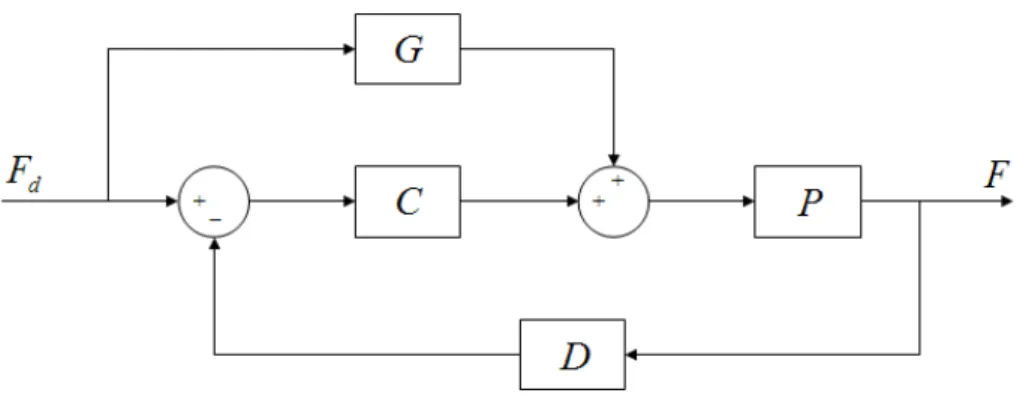
1.1 Collaborative transportation task between a human and a humanoid robot. . . 4 1.2 Structure of a closed-loop force servo controller. C is a
compen-sator, G is a feedforward gain, D is a function applied to force measurements (typically, low-pass filtering), and P is the plant. . . 8 1.3 Robot end-effector (represented by a torus) moving along a bar.
The torus is coupled to a mass which moves along the bar and is subject to viscous friction. . . 9 1.4 Electrical equivalent of a manipulation task at steady state
per-formed by a motion controlled manipulator. . . 10 1.5 Electrical equivalent of a manipulation task at steady state
per-formed by an impedance controlled manipulator. . . 10 1.6 Target mass-spring-damper system. M is the target mass, B the
target damping, K the target stiffness, x0is the virtual compliance
center and x is the position of the mass, which corresponds to the position of the end-effector. . . 13 1.7 Position-based impedance controller. A is the target impedance, C
is a position controller, and P is the plant. . . 14 1.8 One dof point-to-point task. . . 16 1.9 Servo-control approach to collaborative manipulation. One partner
tries to impose a desired position Xd to the object. The partner
applying the force Fdappears as a disturbance to the other partner. 17
1.10 Target equivalent networks for different control schemes: on the left, both partners are position controlled and try to act as a position source. The target network is not feasible. Middle: one of the partners only is position controlled, and the other acts as a force source. The current that flows through the inductance corresponds to the motion of the object and is imposed by only one partner. On the right: target network when both partners are impedance controlled. The network is feasible, and symmetric: both partners can act on the motion of the object. . . 18 1.11 Passive impedance control. . . 20 2.1 Illustration of one degree of freedom homotopy for each
individ-ual of the physical interaction task dyad (holding a table). Each αi∈{1,2} may evolve independently from the other and their time function results on a dynamic sliding between 0 and 1 during task execution. . . 34
2.2 Person-Object-Avatar physical collaborative task architecture and main modules. The solid and dashed lines represent the a priori plans of the partners. The red point represents the starting posi-tion of the object and the yellow one represents the target desti-nation. Two data flows can be seen on the figure. The flow that goes through the light gray boxes represents data that is closely re-lated to the communication with the human partner. The dark gray blocks are more related to the internal state and constraints of the robot. . . 38 2.3 Collaborative task between two virtual avatars. . . 39 2.4 Result of the simulation of a collaborative task between two virtual
humanoids when both act as leader. Left: desired trajectory for each avatar, and actual trajectory of the object. Right: vertical force applied by each avatar. . . 40 2.5 Trajectory of the object when one of the partners is a leader and the
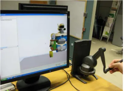
other is a follower in the Avatar-Object-Avatar experiment, where two virtual avatars lift an object and pass it over an obstacle. . . . 41 2.6 Experimental setup: a human operator uses a PHANToM Desktop
device to lift a virtual object in collaboration with a virtual robotic partner. . . 41 2.7 Plan of the virtual avatar: desired motion of the object. . . 42 2.8 Typical joint torques at the joints of the avatar (chest joint and right
arm joints). The torque references sent to the actuators of the robot are smooth even when the value of the homotopy variable changes. 43 2.9 Trajectories when the human leads all the task (blue) and when he
leads part of the task (green). The human trajectory goes further from the obstacle. . . 43 2.10 A human operator and HRP-2 jointly moving an object towards the
left-hand side of the robot. During the motion, the right arm of the robot moves towards the chest, increasing the risk of self-collision. 46 2.11 Evolution of the homotopy parameter and collision distance along
the task performance (bottom graph, solid line: homotopy param-eter, dashed line: collision distance). On the top graph, the trajec-tory of the robot is shown. The blue line corresponds to the plan of the robot, the yellow line corresponds to the actual trajectory followed by the robot. . . 47 2.12 1 degree-of-freedom collaborative positioning task. . . 48 2.13 Profile of the homotopy variable for different values of β . High
values of β give highly specialized profiles. The specialization is less pronounced for small values of β . An unspecialized profile is obtained for β = 0. . . 49 2.14 Simulation model. PDi denotes the Proportional-Derivative
con-troller used to implement the leader behavior. Zf
i denotes the
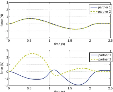
fol-lower impedance controller. . . 50 2.15 Force applied by each partner on the object to reach a common
target position, for different specialization profiles (from non-specialized to fully non-specialized). . . 50 2.16 Force applied by each partner on the object to reach a common
target position: β = 0, unspecialized case (up); β = 1, fully spe-cialized case (down). . . 51 x
2.17 Motion of the object (up), forces applied by the partners (middle) and homotopy parameters of each partner (down). . . 51 3.1 The three variables considered in our study. The vertical force f is
the force exerted on the robot’s wrist. . . 60 3.2 A human (teacher) teleoperates the humanoid robot HRP-2
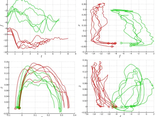
through a force feedback haptic display to demonstrate how to perform a collaborative task with a human partner (operator). . . . 61 3.3 First row: force against time and position against forces. The
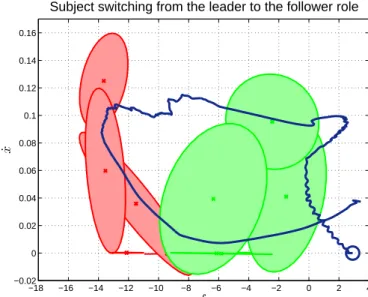
forces in the “leader robot” case (in red) and the “follower robot” case (in green) are clearly separated. Second row: velocity profiles plotted against the position and force variables. The trajectories in red and the trajectories in green correspond respectively to the demonstrations of the robot acting as a leader and as a follower. The circles represent the beginning of the motions. . . 63 3.4 The two sets recorded during the demonstration. The
data-set DL corresponding to the demonstrations with a leader robot
is depicted in red, and the data-set DF corresponding to the
com-plementary role distribution (follower robot and leader human) is shown in green. . . 65 3.5 Gaussian Mixture Models encoding the task dynamics. The red
ellipsoids represent the components of the GMM GL encoding the
task dynamics with the “leader robot-follower human” role distri-bution. The green ellipsoids represent the components of the GMM GF associated with the “follower robot-leader human” demonstra-tions. . . 67 3.6 Illustration of the GMR process. The red plane represents the
im-age of the input space through the GMR process. The orientation of this plane gives information on how the reconstructed output E(p(ξO|ξI)) will vary with the values of the inputs ξI
1and Iξ2I. . . 69
3.7 Illustration of the GMR process with two gaussian components. The surface represents the image of the input space through the GMR process. The blue (respectively red) part shows the area where the blue (respectively red) component has more effect on the value of E(p(ξO|ξI)). In the blue (red) area, the surface is
almost the image plane obtained with only the blue (red) compo-nent such as in figure 3.6. Between these areas, the colors are mixed, since both components will have influence on the output. The figure shows how the blue and red components are used to compute Eblue(p(ξO|ξI)) and Ered(p(ξO|ξI)), which are located
on the cross-ruled planes. These values are weighted to obtain E(p(ξO|ξI)), located on the surface S. . . . 69
3.8 Autonomous replication of a lifting task by HRP-2 jointly with a human partner. . . 71 3.9 Failed reproduction attempts. The object was successfully lifted,
but the dynamics of the motion is not the demonstrated one: the human partner applied very large forces on the object, which we interpret as an unsatisfied will to increase the pace. . . 71 3.10 Reproduction trials where the dynamics of the motion is close to
the demonstrated “human leader-robot follower” task dynamics. . 72
3.11 Reproduction trial where the dynamics of the motion is close to the demonstrated “human follower-robot leader” task dynamics. . . . 72 3.12 Reproduction trials where the dynamics of the motion switched
from the “robot leader” to the “robot follower” dynamics. . . 73 3.13 Reproduction trials where the dynamics of the motion switched
twice between both demonstrated dynamics. . . 74 3.14 Image of the force-position plane through the GMR process. The
ellipsoids represent the components of the GMM, and the surface shows the velocity output E(p( ˙x|x, f )) for each value of the posi-tion x and force f . Orange areas correspond to the higher veloci-ties, and blue ones to the lower velocities. . . 75 3.15 Image of the force-position plane through the GMR process. The
area in light gray is the area where the success criterion is satisfied, i.e.points ξ such that log(L(ξ ,G )) > llim. . . 76
3.16 Left: successful trials. The data-points have been projected on the position-velocity plane. Right: failed trials. By comparing these pictures, we notice that successful trials generally followed the shape suggested by the ellipsoids, and reached a final position that was closer to the demonstrated one, above the final position of the failed trials. . . 76 3.17 In red: area where the robot will behave mostly according to the
“leader robot-follower human” task dynamics. In green: area where the robot will behave mostly according to the “follower robot-leader human” task dynamics. The transition between these two areas is smooth. . . 77 3.18 Trial where the task dynamics switched between both role
distribu-tions. The switching is more apparent on the bottom figure, where the data-points are plotted over the leader and follower areas. . . . 77 3.19 Velocity of the gripper of the robot and value of the homotopy
parameter during one trial. The smooth transition between both task dynamics can be seen from the continuous transition of the homotopy parameter from 1 to 0. . . 78 4.1 Telepresence setup for distant collaborative tasks. . . 85 4.2 End-effector coupling. . . 85 4.3 Discrepancies between the operator and teleoperator’s posture
re-sult in a wrong intention estimation by the distant human partner. . 86 4.4 Top: the teleoperator mimics the operator’s posture; the posture
and attitude of both the distant human and the object are mapped onto the master device. Bottom: the same object is manipulated on both sides, and only the posture of the distant human is mapped onto the mobile haptic interface. . . 86 4.5 End-effector coupling with posture reflection. . . 87 4.6 F-P bilateral coupling: local control on the slave site. . . 88 4.7 Photos of the experimental setup. On the left the operator site with
the human operator and the mobile haptic interface in Munich is depicted. On the right the teleoperator HRP2 and the human col-laborator in Tsukuba are shown. . . 91 4.8 Cooperative telemanipulation task: a) approach, b) grasp, c) lift, d)
put down . . . 93 xii
4.9 Left: teleoperated HRP-2 collaborating with a human on the remote-site. Right: immersed human operator operating the HRP-2 robot using the VISHARD arm. . . 94 4.10 Force and position tracking during experiment. 1: approaching
phase, 2: moving phase, 3: releasing phase, shaded area: human located at the remote site applies forces to the object . . . 95 4.11 Position tracking of body and end-effectors with a dominant
hu-man operator at the master site. Data of the huhu-man operator at mas-ter site is depicted in black, data of the teleoperator in gray. The dashed lines represent the body position whereas the solid lines represent the right hand/end-effector. . . 96 4.12 Position tracking of body and end-effectors with a dominant
hu-man collaborator at remote site. Data of the huhu-man operator at master site is depicted in black, data of the teleoperator in gray. The dashed lines represent the body position whereas the solid lines represent the right hand/end-effector. . . 97 5.1 Four contexts of task realization in the physical common workspace 101 5.2 Cooperative table transportation between an HRP-2 humanoid
robot and a human operator. . . 103 5.3 Virtual coupling of the end-effectors and the body of a humanoid
robot to synchronize the arms and the body of the robot during a collaborative transportation task. Mbase, Bbase, Marms, Barms and
Karmsare the virtual impedance parameters used to couple the arms
and the base, and to generate the motion of the base. Fext is the
force applied by the human operator on the arms. The model de-picted on the right can be seen as desired dynamics for the motion of the body and arms of the robot. . . 106 5.4 Top: velocity of the arms and base using the algorithm of Kosuge
with time delay. Middle: distance between the arms and base. This distance must be kept slow enough to fit the workspace of the robot. Bottom: virtual force applied on the base of the robot due to the virtual coupling between the arms and base. . . 107 5.5 Velocity of the arms and base using the algorithm of Kosuge
with-outtime delay. Compared to the case with time delay, the velocity profiles are smooth. . . 108 5.6 Top: lateral swinging motion of the waist during on-place stepping
of the robot. The amplitude of the motion is about 10 cm. Bottom: reduced oscillations of the gripper (amplitude of about 1 mm) after the compensation of the legs’ motion. . . 109 5.7 Decoupled admittance control and gait: the admittance of the
end-effector of the robot is a damper fixed to the ground rather than to the body of the robot, allowing to decouple force-based control from the motion of the body of the robot. . . 109 5.8 Reference frames used for the synchronization of the feet and hands.110 5.9 Safe area for the landing foot. . . 111
5.10 Graph of entities at a given time of the control (particular case of the teleoperation experiment presented in the previous chapter). Such a graph is useful to have an idea of the data flow in a given control architecture and can be generated using a simple command
line. . . 113
5.11 Simplified view of the architecture used for the collaborative trans-portation experiment. OpenHRP is used as a proxy between the robot and the Stack of Tasks control architecture. From the state of the robot, a relative position error between the end-effectors and the feet of the robot is computed, and resulting footprints are planned and sent to the pattern generator. From these footprints, the pattern generator computes a reference CoM trajectory and ref-erence trajectories for the feet. The Stack of task then computes a global control law to realize the CoM and feet trajectories as well as the admittance control of the end-effectors, which has the lowest priority. . . 114
5.12 Reference and real ZMP in a direct interaction experiment. On the right: zoom between t = 40s and t = 50s. . . 117
5.13 Force exerted on the right wrist (component along the axis of the forearm). The impacts due to the steps of the humanoid robot result in additional noise in the signal. Overall, during direct physical interactions between the robot and human operators, the applied forces rarely exceed 10 N. . . 118
5.14 Experimental results: direct interaction between a user and the HRP-2 robot . . . 119
5.15 Cooperative table transportation between an HRP-2 humanoid robot and a human operator. . . 120
5.16 Motion of the robot during one trial of the final demonstration sce-nario for the Robot@CWE (top view). The dashed gray line shows the rough trajectory of the robot. The arrows correspond to snap-shots of the position and orientation of the robot every 3s. The red part corresponds to the beginning of the scenario, when the robot walks autonomously, following a computed plan. The purple part corresponds to the first teleoperation phase, where the robot is teleoperated to walk towards the object to transport. The blue part corresponds to the collaborative transportation phase. . . 121
A.1 Two-port model of a teleoperation setup interacting with the hu-man operator on master site and the remote environment. . . 129
A.2 Two-port model of a teleoperation setup with bounded impedances at the interaction ports. . . 130
A.3 FP control architecture. . . 132
A.4 PF control architecture. . . 132
A.5 Network representation of the F-P architecture. . . 133
A.6 Stability envelope for the P-F architecture. mm= 5 kg. . . 134
A.7 Stability area for the F-P architecture. ms= 5 kg. . . 134
B.1 Experimental setup: collaborative lifting task between an HRP-2 humanoid robot and a human subject. . . 136
C.1 Structure of the demonstrator . . . 143 xiv
C.2 The different steps of the simulation: (a) Go to initial configuration (b) Trigger the robot by patting its hand (c) Show it the object (d) Move the object together . . . 144 C.3 Interacting with the HRP-2 avatar using a haptic device. . . 144 D.1 Mechanical parts of the new SensAble 6dof stylus with force
feed-back integration. . . 149 D.2 Different views (left side and isometric) of the new PHANTOM
6dof handle with the 6dof Nano43 force sensor from ATI. . . 150 D.3 A 6dof PHANTOM device with 6DOF sensing sensor from ATI
(Nano43) and the new handle. . . 150
List of Tables
1
Haptic interaction: a survey
Contents
1.1 Introduction . . . 3
1.1.1 Humanoid robots . . . 3
1.1.2 Haptic collaborative tasks . . . 3
1.1.3 Interaction control and the leader-follower model . . . 5
1.1.4 Human-human collaboration . . . 5
1.2 Impedance control . . . 7
1.2.1 Force control and compliance control . . . 7
1.2.2 Impedance control . . . 8
1.2.3 Contact instability . . . 14
1.2.4 Conclusion . . . 15
1.3 Impedance control and collaborative tasks . . . 15
1.3.1 Why impedance control? . . . 16
1.3.2 Applications in the previous works . . . 17
1.3.3 Limitations . . . 19
1.3.4 Conclusion . . . 21
1.4 Recent advances: towards perfect followers? . . . 22
1.4.1 Human impedance models . . . 22
1.4.2 Active following . . . 23
1.4.3 Proactive behaviors . . . 25
1.4.4 Leader robots? . . . 25
1.4.5 Conclusion . . . 26
1.5 Conclusion . . . 26
O
NE of the features of human beings is their ability to collaborate toper-form tasks. Collaborative tasks range from searching an object, piloting a plane to handing over objects, dancing, assembly tasks or daily bulky or heavy object transportation, etc. In this work, we are interested by tasks which involve physical contacts between two partners, typically manipulation tasks where more than one agent act on an object of interest to the task. More specifically, our main target is to achieve a similar task on virtual or robotic avatars such as humanoids (virtual or robotic ones). In the long term, we aim at enhancing robotic or virtual avatars with physical interaction cognition so that they become more human-like partners in physical collaborative tasks.
2 Chapter 1. Haptic interaction: a survey
In this chapter, we introduce haptic collaborative tasks and present different problems that must be solved to give a robotic system the ability to perform such tasks jointly with a human partner. We introduce the leader-follower model, which has been used (often implicitly) in most research works in the field of physi-cal Human-Robot-Interaction (pHRI). We also present some knowledge gathered about human-human behavior in physical collaborative tasks. This knowledge gives insight on how to partially answer one of the problems that characterizes collaborative tasks, namely load sharing. Since most works in pHRI are based on impedance control, we recall its fundamentals and highlight the reason for its use in pHRI. Finally, a summary of the previous works in the field is given, showing a trend to give more and more responsibility to the robotic partners for the realiza-tion of collaborative tasks, which culminates in assigning leader roles to the robot, which is the keystone of next chapter.
1.1. Introduction 3
1.1 Introduction
1.1.1 Humanoid robots
Humanoid robots are robotic platforms whose overall shape is similar to the hu-man body: it generally features a torso, two arms, and a head. Some platforms consist in a humanoid torso mounted on a mobile base, such as the ARMAR hu-manoid robot [4], and other are bipeds, such as Honda’s ASIMO, or robots from the HRP series. In this thesis, we will implicitly refer to this second category when mentioning humanoid robots.
Biped humanoid robots are redundant, free-floating robots, which require ap-propriate motion control strategies to synchronize all the parts of their body to per-form different tasks. As walking systems, humanoid robots have a wide workspace, but can fall (lose their static or dynamic balance). Static walking refers to gait where the robot is constantly in static equilibrium. This condition is not necessary to walk without falling: the ZMP criterion [114] has been widely used as a basis for dynamic walking.
1.1.2 Haptic collaborative tasks
The goal of this work is to study how a humanoid robot can be endowed with the ability to perform haptic collaborative tasks with a human operator. The redun-dancy that characterizes humanoid robots and their shape make them polyvalent tools that can potentially exert various physical works (pick up and manipulate ob-jects, repair vehicles, assembly tasks) in various environments (homes, offices or hostile environments). Contrary to industrial robots, humanoid robots are expected to spread in everyday’s environment such as homes and offices. Thus, humanoid robots must be able to operate in the same workspace as humans, and are likely to interact with them. One paradigm of interaction takes form through physical contact between the agents, and occurs in different contexts, such as involuntary contact, pushing aside, handshaking, dancing, transporting objects and so on.
Situations where the dynamics of a human and a robot are coupled by direct contact or contact through an object, are referred to as physical Human-Robot In-teraction, or pHRI. We will focus on the case where the contact is intentional, and established by the human and robotic partners to perform a collaborative task. In such configurations, we believe that haptic cues play an important role, hence we will call these tasks haptic collaborative tasks.
More precisely, we will study dyadic collaborative manipulation tasks. A col-laborative manipulation task is an instance of haptic collaboration whose goal is to modify the position and orientation of an object with time, by applying forces on the object. We look at the case where two partners participate to the task, and aim at the realization of such tasks by a human operator and a humanoid robot. An instance of collaborative manipulation task is shown on figure 1.1.
To achieve a task such as the one depicted on figure 1.1, a mutual adaptation processmust take place between the partners, at different levels, which are detailed below.
Dynamic interaction
The dynamics of the human operator and the humanoid are coupled by contact with a common object. This must somehow be taken into account in their
con-4 Chapter 1. Haptic interaction: a survey
Figure 1.1 – Collaborative transportation task between a human and a humanoid robot.
trol strategies: their motions must be coordinated to keep contact with the object and maintain interaction forces at a reasonable level while moving towards a goal configuration. When both systems are coupled, they also have to take into account their respective constraints. As we are considering bipeds, one very important constraint is keeping dynamic balance. The mechanical power flow between the partners must be appropriately absorbed or transformed into kinetic energy in order not to fall. One way to do this is to perform steps.
Load sharing
The goal of collaborating to perform a manipulation task is to share the task load. For simple tasks, this mainly consists of sharing the physical load, i.e. by sharing the inertial load and countering the effects of friction or any other dissipative ef-fect. For more complex tasks, this can also imply sharing a cognitive load. When performing a collaborative manipulation task, the partners have to agree on a load sharing strategy so as to act in a complementary way.
We can imagine several ways to share the cognitive load during a task, by decomposing the task into subtasks. For example, when transporting a table upon which a vase is standing, one partner can ensure a desired trajectory of the table in the horizontal plane, while the other can adjust the altitude of the table and ensure it is kept horizontal. There is no guarantee, however, that this decomposition will be natural for a human operator. Hence, to devise cognitive load sharing strategies for a robotic partner, we must first understand how humans themselves decompose tasks, if they do so.
The problem of sharing the physical load is unfortunately not simpler. In order to move an object, only a 6-dimensional force/torque vector is necessary. When two partners move the same object, they form a redundant system, as an infinite set of pairs of force vectors can be applied to result in the same motion. The set of possibilities is only limited by the constraints of each partner, namely, their balance and their muscular force. Here also, the study of human-human collaboration can provide useful information.
Planning
When two humans perform a collaborative manipulation task, they both might have their own initial plan. However, the object will finally follow only one trajectory to move from its initial to its final configuration. This means that either one of the partner has to totally ignore her/his initial plan, or that the plans of both partners must be adapted to result in a final, common plan. Somehow, we can say that collaborative tasks must be negotiated by the partners.
1.1. Introduction 5
1.1.3 Interaction control and the leader-follower model
Previous works in pHRI are articulated around two concepts: interaction control, and the leader-follower model. Interaction control is an approach of robot control that addresses the problem of dynamic interaction between robots and their en-vironment. Whereas servo control aims at tracking reference signals, interaction control places interactive behavior above command following in the design crite-ria [15]. A well-known instance of interaction is impedance control [44], which has been used as a basis for a great amount of research in pHRI [3, 64, 70, 86, 110]. Besides impedance control, a common model use in pHRI is the leader-follower model. According to this model, one agent (the leader) has knowledge about the tasks and imposes his plan to his partners. Generally, the robot is as-signed a follower role. While most works imposed a passive behavior to the robot, some researchers argued that passive following increased the necessary work to be performed by the human operator in order to move the object, since the robot is dissipating part of it [16, 70]. They proposed active following schemes for point-to-point tasks, where the robot predicts the human motion, based on the minimum jerk model [31]. In such schemes, the limit between the leader and the follower roles becomes fuzzier. When the robot fails to estimate the human intentions, the human partner can adapt to the resulting motion of the robot instead of sticking to his or her original intentions. Hence, active following does not mean the absence of mutual adaptation.
Even if they can actively follow human operators, robotic systems have gen-erally not been programmed to have their own task plan and negotiate it with the human operator: the human partner is almost always leading the task. We believe that such a binary, fixed role distribution does not reflect the strategies adopted by two humans when they jointly perform physical tasks. We propose to extend the leader-follower model to a continuous, time-varying distribution between the two roles. This idea is formalized in the next chapter and is the keystone of the first part of this thesis.
1.1.4 Human-human collaboration
To implement efficient collaborative behaviors on a robotic system, it can be in-teresting to understand how humans themselves perform collaborative tasks. The study in [75] shows that the minimum jerk model does not hold for collaborative point-to-point tasks. In this study, an object is moved from one place to another, in two conditions: by one partner alone, or by two partners. When the task was performed by two partners, the mass of the object was doubled. The comparison between these two conditions shows that the object reaches higher altitudes when manipulated by two partners. However, the velocity profiles obtained in the case where two partners manipulate the object was close to the average between the velocity profiles obtained with each partner alone.
In his thesis, Kyle Reed thoroughly studies the state-of-the-art in human-human physical interaction and in the related fields: human-human motion control in free space, human-robot physical interaction and tele-operation [90]. Kyle Reed then studies a one degree-of-freedom symmetrical task, where two partners turn a crank to reach a common target angle. He noticed, among others, a difference force (which produces no motion) in the steady state, when partners have reached the target and stop. He speculates that this contraction could help partners stabilize the system or feel each other. He also validated Fitt’s law [30] for dyads, though he
6 Chapter 1. Haptic interaction: a survey
pointed out that Fitt’s law did not apply when both partners were given conflicting target positions [92].
His major result is highlighting a phenomenon he named specialization. Ex-perimental results showed that after several trials, the force patterns applied by the participants change so that each partner contributes to a subtask and hinders the other subtasks. During his experiments, most dyads adopted an accelera-tion/deceleration specialization: one partner will accelerate the crank at the begin-ning of the motion, while the other one will decelerate it during the second part of the movement. Other dyads, though eventually adopted a left/right specialization: one partner contributed to motions in one direction and vice-versa. The hypothetic reasons for specialization are the resolution of the redundancy and increase per-formance by focusing on one subtask only. He could yet not determine how the humans specialize (except that it establishes via the haptic channel), neither who specializes for which subtask, nor why. It is essential to underline that the task he studied was symmetrical, thus it did not suggest any specialization a priori.
Reed tried reproducing the performance of human dyads with human-robot dyads. In his experiments, the human-robot was applying a “specialized” force profile that was obtained by averaging the profiles of a human subject. Though the setup did suggest a (complementary) specialization for the human, the latter kept an unspecialized force profile during all the trials. The mechanism of com-munication through which specialization emerges is thus not characterized, and yet not understood. Reed suggests that the human subjects did not specialize because the robot was specialized from the first trials. He cites the work of Corteville et al.[16], where a human adapted his motion according to the behavior of the robot. In these experiments, the robot was also adapting to the motion of the human. This adaptation of the robot to the human is maybe a necessary process for the human to also adapt his force profile.
Specialization could partly answer the problem of physical load sharing, as it can be seen as a way to resolve redundancy. The question is yet not totally solved, since the works just cited are purely descriptive. We do not know how to generate the described behavior, given the fact that what is described is a joint behavior of the robotic and human partners, and we can only control the robotic partner. However, from the works presented in this paragraph, we can extract the following information:
⊲ the output behavior of a dyad as a whole can be (but is not always!) an average of the behaviors of the individuals [75];
⊲ the physical load can be shared by specializing for subtasks [90];
⊲ specialization is an emerging phenomenon, which means that any attempt to model it should take into account “degrees” of specialization (unspecialized, hardly specialized, totally specialized).
Specialization will be mentioned again in the next chapter, where it is related with our continuous, time-varying, role distribution hypothesis. The model pro-posed in the next chapter encompasses the three concluding remarks of this para-graph. The remainder of this chapter recalls the fundamentals about impedance control, and shows why it is a relevant control scheme for haptic collaboration. Then, a critical review of previous works in pHRI is presented and we evaluate to what extent the problem of physical collaboration is solved (or unsolved). We conclude this chapter by summarizing the main ideas defended in this thesis.
1.2. Impedance control 7
1.2 Impedance control
When a human operator interacts with a robotic system, it is necessary to limit, to some extent, the interaction forces to prevent injuries of the human partner. Con-trolling forces is precisely the purpose of force control. However, among force controllers, two categories can be distinguished: explicit force controllers, and implicit force controllers. Controllers of the first category follow the design spec-ifications of servo controllers, which focus on tracking a signal, treating the en-vironment as a source of disturbances. Impedance control belongs to the second category, but restricting impedance control to a form of force control is restrictive. Impedance control actually falls under interaction control, which places interac-tive behavior above command following in the design specifications [15]. This section first recalls some facts about force control, and then goes into the details about impedance control, to highlight the aspects that make impedance control an appropriate control strategy for pHRI.
1.2.1 Force control and compliance control
Motion control consists in sending commands to the robot so that a given point on the robot tracks a desired motion. Motion control is efficient for robotic tasks which do not involve interaction with the environment, such as spray-painting, or any task which only requires trajectory tracking in free space. When the motion of the effector is constrained, however, there exist directions along which the mo-tion can no longer be controlled and is imposed by the environment. On these directions, the interaction force resulting from the environment constraint can be controlled.
Force control consists in controlling, directly or indirectly, the forces ap-plied by the manipulator on the environment. Force control appeared in the early 1970s [49, 50, 100], and was formalized mainly in the second half of the decade [17, 74, 82, 94, 117]. Force control and position control are often jointly applied, in complementary subspaces [17, 74]. Force control is applied along the constrained direction of the manipulator, and position control is applied on the unconstrained ones.
Two different issues are actually considered in what is called “force control”. The first one, sometimes referred to as “explicit force control” consists of track-ing a desired interaction force between a manipulator and its environment. This can be done in an open-loop fashion, based on the dynamic model of the manipu-lator and the environment, but more precision can be achieved by closing the loop around force measurements. Figure 1.2 shows a basic structure for closed-loop force control. Note that force controllers can be built around inner position or velocity control loops (see e.g. [58]).
The second one is concerned with positioning the manipulator while limiting to some extent the interaction forces. Stiffness, damping and impedance control fall under this category. This objective can be achieved by defining a relation between the position error and the contact force. Since the basic idea is to generate motions that comply to the environmental constraints, this strategy can be termed compliance control[44].
The first approach belongs to servo control, and as such does not take into account the dynamics of interaction between the manipulator and the environment. This means that if the robot interacts with a human operator, or with another robot,
8 Chapter 1. Haptic interaction: a survey
Figure 1.2 – Structure of a closed-loop force servo controller. C is a compensator, G is a feedforward gain, D is a function applied to force measurements (typically, low-pass filtering), and P is the plant.
these will be considered as sources of disturbances and the actions they will take will be rejected by the controller. As will be shown in the remainder of this section, the second approach is more appropriate for pHRI, especially for manipulation tasks, which are formulated in terms of desired motions rather than desired forces. A complete review of the field of force control, providing implementation details, can be found in [69]. The next paragraph gives further details about impedance control and briefly presents two categories of implementation of impedance controllers.
1.2.2 Impedance control
Impedance control [44] can be seen as a generalization of stiffness and damping control. The main point of impedance control is that it defines a physically con-sistent framework for the control of robotic systems that interact with their envi-ronment. This framework has been extended in [15], where the difference between servo controland interaction control are clearly stated in terms of objectives, re-sulting in two different approaches to design controllers: in interaction control, the so-called interactive behavior has more importance than command following. Intuition
Position and force control are appropriate when the environment of the manipula-tor is perfectly modeled and can be treated as kinematic constraints on the robot’s motion. Consider a robot with a torus end-effector sliding along a bar without fric-tion: along the bar, the motion of the robot is not constrained, but in the orthogonal directions, no motion is possible. However, forces can be applied along these di-rections. Assuming the position of the bar is exactly known, hybrid controllers [88] will allow to perform any desired motion along the bar and to apply any desired force in the orthogonal directions. The only limitation to the motions and forces come from the capabilities of the robot itself. Note, also, that no mechanical power flows between the robot and its environment during the task.
Let us consider the same environment, where this time dynamic constraints are imposed to the manipulator: the manipulator is coupled to a mass, which can only slide along the bar, subject to viscous friction (see figure 1.3). This task corresponds to a one degree-of-freedom manipulation task, except that the contact between the robot and the object to be manipulated (the mass) is bilateral.
1.2. Impedance control 9
Figure 1.3 – Robot end-effector (represented by a torus) moving along a bar. The torus is coupled to a mass which moves along the bar and is subject to viscous friction.
Because the end-effector of the robot is coupled to the mass, its motion is no longer unconstrained. The motion of the end-effector will be constrained by the dynamic equations that govern the motion of the mass the robot is coupled to. Because of this coupling, on the same direction (along the bar), the robot will experience both force and motion: in other terms, mechanical power will flow between the robot and its environment.
If the mass and the damping it is subject to are significant, the robot will be able to accelerate the object arbitrarily or attain arbitrary high velocities only at the expense of a significant energy. The highest the mass is, the more energy will be necessary for high frequency motions. When the damping increases, lower veloc-ities can be attained for the same mechanical power provided by the robot. This means that if the robot acts as a position source (which would the target behavior of a position controlled system), then to avoid too high energy flows, the desired motion of the system should be adapted. If this motion is computed off-line by a planner, this will severely limit the applicability of the system (each trajectory will be compatible with only a range of masses and dampings), or will require ad-hoc trajectory adaptations for new environments. In environments with uncertainties or variability, this approach is impractical.
To introduce impedance control as a solution to this power flow problem, let us use electrical analogies. Instead of considering force and motion, we will consider voltage and current. Intuitively, motion control with a servo approach aims at mak-ing the manipulator behave as a motion source. At steady state, this motion can be countered by resistive elements in the environment like dampers, whose electrical equivalent are resistors. Hence, a position controlled manipulator performing a manipulation task at steady state can be modelled by the electrical network shown on fig 1.4.
For very resistive environments, the power flow between the manipulator and the environment is P = R i2
dand will increase with the resistance of the environment
(i.e. as the environment admittance decreases to zero) for arbitrarily high desired currents id. One way to control the power flow between the manipulator and the
environment is to add a second resistor in parallel with the environment, as shown in figure 1.5.
10 Chapter 1. Haptic interaction: a survey
Figure 1.4 – Electrical equivalent of a manipulation task at steady state performed by a motion controlled manipulator.
Figure 1.5 – Electrical equivalent of a manipulation task at steady state performed by an impedance controlled manipulator.
but as a voltage source, where the voltage depends on the difference between the desired current and the current flowing through the environment. The volt-age across the environment terminals and the power flow between the manipulator and the environment are given by:
ud = Rd(id− i) P = R 2 d(id− i)2 R (1.1) where Rdis a controller gain. Now, if R increases, the network is transformed into
the circuit of figure 1.4, except that this time, the resistance is Rd and is set by the
designer. Hence, in case of very resistive environments, the power flow will be bound by Rdi2d. When the resistance of the environment becomes close to zero,
then i = id, ud= 0 and no power flows through the environment. This degenerated
case corresponds to unconstrained motion, and the equivalent network is no longer feasible, since current flows are ideal elements. The important point is that the power flow between the manipulator and the environment will tend to zero as the environment resistance decreases, and be bounded by Rd i2d as the environment
1.2. Impedance control 11
value of Rd for arbitrarily large desired currents id, but the bounds on the power
flow now entirely depends on the manipulator control system and do not depend on the environment. Moreover, the resistance parameter Rd can be adjusted to
allow for higher desired velocities for a given maximum power flow, at the cost, of course, of potentially larger current errors i0= id− i.
This electrical analogy illustrates the purpose of impedance control. In impedance control, the target system is not a pure position source, but a position source with a target dynamic response to motion errors. The difference with pure motion control is that the primary goal is not to reject all disturbances and track a desired motion. The primary goal is the dynamics of the response to the motion errors. Command following comes after, and will be ensured when no disturbance occurs. One of the effects is that the mechanical power flow between the manipu-lator and the environment is somehow controlled, which is an important criterion to avoid physical damage of the manipulator or the manipulated object.
One can argue that motion control would in reality have exactly the same struc-ture as impedance control. In our electrical network on figure 1.5, by using very high values for Rd, we tend to make our manipulator behave as a pure current
source. Likewise, in control theory, position controllers are often implemented using Proportional-Derivative (PD) controllers, which corresponds to coupling the object to the desired position using a virtual spring-damper system, which is a com-mon target dynamics in impedance control, as will be seen further in this section. Stated like this, there seems to be no difference in the structure of a PD posi-tion controller and an impedance controller. However, the goal of posiposi-tion control is to make the manipulator behave as a motion source, which is not the case in impedance control. On figure 1.5, position control will want very high values for Rd, while this is generally not the case with impedance control.
Note that the general case of impedance control considers any form of impedance. Our electrical example contained only resistors, which are the electri-cal equivalent of dampers. More general impedances could have been considered by including inductances (the equivalent of masses) and capacitors (the equivalent of mechanical springs). We now briefly present the history of impedance control, admittance control, and, more generally, interaction control.
Impedance control: a history
Impedance control was proposed by Neville Hogan [44] as an alternative to pure position or force control and hybrid control. As Hogan pointed out, neither position nor force control allows the control of the mechanical energy exchanged between a robotic system and its environment. Since the mechanical energy transfer at the interaction port depends on both the velocity and force variables, he proposed to impose a relation between them.
The approach proposed by Hogan consists of imposing a dynamic behavior to the system. Thus, instead of tracking either the interaction force or velocity of the robot’s tool tip, a dynamic relation between the two variables is enforced. This allows the control of the mechanical power flow between the robot and its environment, which is defined by the product of force and velocity. Hogan also postulates that no controller can make the robot manipulator appear as anything but a physical system to the environment. As a result, the manipulator can not impose both a velocity and a force to the environment at the interaction port, but only one of them. Two categories of systems can be distinguished: impedances,
12 Chapter 1. Haptic interaction: a survey
which input flow and output effort, and admittances, which input effort and output flow. As the environment of a robotic manipulator arm is mainly composed of inertial loads, which are admittances, Hogan states that, to be compatible with its environment, the manipulator should be controlled to appear as an impedance, hence the term “impedance control”.
Citing the case of robots jointly performing a task, Colgate suggests that the control of systems that dynamically interact with their environment requires a dif-ferent approach from servo control [15]. In servo control, the environment of the control system is generally seen as a source of disturbances to be rejected. This approach is not suitable when the environment is composed of other robots or hu-man operators. Compared to servo control, Colgate adds coupled stability and interactive behavioras design criteria for interaction control. Coupled stability is obtained if the system remains stable when coupled to any environment. Interac-tive behavior focuses on the dynamics of the overall system in interaction with its environment, whereas in servo control, the stress is put on tracking a desired trajec-tory for one single variable (in the Single Input, Single Output case). Colgate also derives a necessary and sufficient condition for linear systems to be stably coupled to passive environment: the controlled system must exhibit a positive real driving point impedance. This result is extended to active system under the condition that the system and the state-dependant control together are passive, and the active part is state-independent. Finally, a systematic approach is proposed to design inter-action controllers to obtain both stable coupling and good performance (namely, command following and interactive behavior). The coupled stability constraint relies on the concept of “worst environment”, which are the most destabilizing.
Whereas Hogan states that manipulator arms physically interacting with their environment should behave as impedances, a common control scheme for robots physically interacting with their environment consists in taking into account force feedback within the position control loop. This corresponds to admittance control. Admittance controllers are easily built upon low level position controllers by com-puting the position command depending on the force feedback. They are suitable on platforms with high inertia and friction. More specifically, dry friction tends to decrease the performance of force controllers. This problem can be overcome by using a high-gain position controller; the admittance controller then computes position commands from a force signal, which has to be measured by a sensor. Admittance controller can be implemented on devices with a large workspace and can display high stiffnesses, but generally have a reduced bandwidth compared to impedance controllers [112]. Note that when the robot is directly interacting with a human (such as haptic interfaces), if we consider the human as an impedance, then the robot can be admittance controlled without breaking causality.
It has been suggested [57] that “impedance control” would be an inappropriate term to refer to the control strategy proposed by Hogan. The main argument is that the input of the controller is a desired position, and impedance controllers simply define a dynamical relationship between the force exerted on the environment and the position error. Hence, impedance control would fall under position control, and since the generated motion is compliant, the term “compliant motion control” is proposed. This is merely a matter of vocabulary, nevertheless it is important to state that the approach adopted in impedance control and position control are totally different. Impedance control does not belong to servo control, whereas position control traditionally does. In position control, the environment is seen as a source of disturbances to be rejected, and command following has a high priority
1.2. Impedance control 13
in the design criteria [15]. Impedance control is rather focused on the dynamic behavior of the overall system when the environment and manipulator dynamics are coupled (as in contact situations) [44, 47]. Command following has a lower priority with respect to interactive behavior [15].
To conclude about this vocabulary issue, let us say that in impedance control (or compliant motion control), finally, neither the force nor the position are con-trolled, since they both depend on the environment the manipulator interacts with. The position will only be controlled in the free space, while no force command is explicitly given to the controller. The only defined entity is the manipulator impedance, i.e. its force response to motion inputs. Thus, we feel that “impedance control” is as valid as a term as “compliant motion control”, keeping in mind that this control strategy does not belong to servo control anyway.
Impedance control implementations
Roughly speaking, impedance control consists in defining a target dynamics and controlling the manipulator to track this desired dynamics. A usual target dynamic behavior is to make the end-effector behave as a linear mass-spring-damper system, such as in figure 1.6.
Figure 1.6 – Target mass-spring-damper system. M is the target mass, B the target damp-ing, K the target stiffness, x0is the virtual compliance center and x is the position of the mass, which corresponds to the position of the end-effector.
The target system dynamics is described by the following equation:
M ¨x = f + B (˙x0− ˙x) + K (x0− x) (1.2)
where M, B, K are the target mass, damping and stiffness of the system, x is the position of the end-effector of the manipulator, x0is the equilibrium position, and
f is the external force applied on the end-effector.
The initial implementations proposed by Hogan [45, 46] target torque con-trolled manipulators, i.e. manipulators that are concon-trolled by specifying desired actuator torques. On such manipulators, impedance control can be implemented using resolved acceleration control. If force sensing is not available, but the dy-namic model of the manipulator is known, arbitrary damping and stiffness coeffi-cients can be chosen, but the manipulator inertia can not be changed: that is, the target mass M must be the actual apparent mass of the manipulator, obtained by projecting the inertia matrix in the operational space. If the dynamic model of the manipulator is not available, the target dynamics can be approximated, if the tar-get inertia is the actual manipulator inertia, by specifying the following actuator torques:
τa= J(q)T(B (˙x0− ˙x) + K (x0− x)) (1.3)
where J(q) is the manipulator jacobian, and q is the configuration vector of the manipulator.
14 Chapter 1. Haptic interaction: a survey
Many robotic platforms cannot be controlled by specifying desired torques, but by specifying desired positions or velocities. In this case, the impedance controller is built around the inner position or velocity control loop. This means that the output of the controller is no longer a force, but a motion. For this reason, the control scheme might be considered as an “admittance controller”. However, since we consider a nominal position, which will be tracked whenever the manipulator is in free space, we can still consider motions as the input of the overall control system. Hence, the term “position based impedance control” can be found in the literature. We will use either of them in this thesis.
Position-based impedance controllers require force sensing devices. The sensed force is integrated using equation (1.2), to obtain a reference velocity ˙x and/or a reference position x to send to the inner position controller. Figure 1.7 shows the structure of a position-based impedance controller.
Figure 1.7 – Position-based impedance controller. A is the target impedance, C is a position controller, and P is the plant.
Position based impedance controllers offer the advantage of a certain simplicity of implementation, since the manipulator dynamics are masked behind the inner motion control loop. However, they loose the advantage of passive compliance, which is a significant on redundant manipulators. Indeed, the output of a position-based impedance controller is a vector of joint positions to be sent to an inner high-gain joint position controller. This means that the posture of the robot will be fixed for a given sensed force, even if the manipulator is redundant. On the other hand, torque-based impedance controllers produce an output torque as a ref-erence for each joint of the manipulator. It is then possible for an operator to modify the posture of a redundant robot by applying forces at arbitrary points of the robot; the posture of the robot will be modified according to the dynamics of the manipulator under the constraint that the end-point dynamic behavior imposed by the impedance controller is unchanged. Position-based impedance controllers also suffer from other drawbacks: the performance of such controllers is depen-dant on the quality of the inner position control loop [67]. Finally, time delays in the control law computation, and due to the transmission dynamics tend to have a greater impact on contact instability.
1.2.3 Contact instability
Stability (having a bounded output in response to bounded inputs) is the most im-portant design criteria for a controller. Among the robotic tasks, those that involve physical contact with the environment are prone to instability. In position and force control, these instabilities can arise because these approaches focus on the regulation of one variable and neglect the dynamics of interaction [46]. However, the dynamics of the robotic system before and after physical contact dramatically