HAL Id: hal-01495199
https://hal.archives-ouvertes.fr/hal-01495199
Submitted on 24 Mar 2017
HAL is a multi-disciplinary open access
archive for the deposit and dissemination of
sci-entific research documents, whether they are
pub-lished or not. The documents may come from
teaching and research institutions in France or
abroad, or from public or private research centers.
L’archive ouverte pluridisciplinaire HAL, est
destinée au dépôt et à la diffusion de documents
scientifiques de niveau recherche, publiés ou non,
émanant des établissements d’enseignement et de
recherche français ou étrangers, des laboratoires
publics ou privés.
Real time 3D geometry correction for folding screens or
projectors with distorting lenses
Fabien Picarougne, Aurélien Milliat
To cite this version:
Fabien Picarougne, Aurélien Milliat. Real time 3D geometry correction for folding screens or projectors
with distorting lenses. VRST ’16 22nd ACM Conference on Virtual Reality Software and Technology,
Nov 2016, Munich, Germany. VRST ’16 Proceedings of the 22nd ACM Conference on Virtual Reality
Software and Technology, pp.353 - 354, 2016, �10.1145/2993369.2996326�. �hal-01495199�
Real Time 3D Geometry Correction for Folding Screens or Projectors with
Distorting Lenses
Fabien Picarougne∗ LINA, University of Nantes
Aur´elien Milliat† LINA, University of Nantes
Abstract
In this article, we describe a new method for real-time display, in a geometrically correct way, of a 3D scene on curved surfaces. This method differs from existing solutions in the literature by allow-ing its application with foldallow-ing screens or projectors with distortallow-ing lenses. Our algorithm is not limited to a particular shape of the display surface and takes the position of the user into account to display an image that is geometrically correctly perceived from the user’s viewpoint. The projection process of 3D objects is divided in three phases. The first two steps are independent from the 3D scene and act as a buffer that stores particular values and accelerate cal-culations of the third step. The execution of the later may then be performed in linear time in the number of vertices of the geometry to be displayed.
Keywords: 3D, geometry correction, curved surface, folding screen, real time
Concepts: •Computing methodologies → Rendering; 3D imag-ing;•Hardware → Displays and imagers;
1
Projection on curved surface
Virtual reality equipment (VR) are increasingly used for industrial, recreational and educational. After several years of evolution, 3D and highly immersive image projection systems for multi-walled stereoscopic environments have reached maturity. However, devel-opments are still active, and users want now to view immersive content on complex surfaces. For example, large flight simula-tors traditionally use cylindrical projection screens or dome projec-tion screens, planetariums and Omnimax theaters use hemispherical screens. However, the projection of images on these non-planar sur-faces requires correcting the geometry of the image to be visually correct from the perspective of the user.
Since the 90s, several solutions have been proposed to solve the problem of distortion with real-time correction. In the literature, we distinguish four main approaches for displaying content on non planar surfaces. 1) Ray tracing. But this method is extremely costly in calculation time and yet cannot be real-time for high resolutions. 2) Image rendering in two passes. It consists in generating and distort an image by mapping it on a grid that takes the form of the displayed surface. But this method requires a good knowledge of the parameters of the projection system in use in order to parametrized the mapping grid. 3) Projection mapping technique [Raskar et al. 1998]. This rendering technique also
∗e-mail:[email protected] †e-mail:[email protected]
Permission to make digital or hard copies of part or all of this work for personal or classroom use is granted without fee provided that copies are not made or distributed for profit or commercial advantage and that copies bear this notice and the full citation on the first page. Copyrights for third-party components of this work must be honored. For all other uses, contact the owner/author(s). c 2016 Copyright held by the owner/author(s). VRST ’16, November 02-04, 2016, Garching bei M¨unchen, Germany ISBN: 978-1-4503-4491-3/16/11
DOI: http://dx.doi.org/10.1145/2993369.2996326
acts in two passes, but instead of parameterizing a grid to model the displayed surface, it renders into a texture the 3D scene to display as seen from the viewer’s position and projected it onto a 3D object that model the surface to be displayed, as if a projector was located at the viewer position. But this method makes the hypothesis that the image is displayed by a classical projector with a standard central projection: not applicable with distorting lenses or foldable screens. 4) Transfer on quadric surface. Here, we directly modify the coordinates of the 3D objects to display, according to the curvature of the display surface and the position of the user. This technique requires only one rendering pass but current implementations therefore limit the kind of display surface used to quadrics in order to simplify the final calculation.
We propose in this article to improve and generalize the use a curved display surfaces for viewing 3D objects by using classical GPU pipeline. Our method takes into consideration a display sur-face of any shape and any type (foldable screen, projectors poten-tially having distorting lenses. . . ) together with the position of the user and performs a real-time geometric correction. These data can also be updated dynamically, keeping the calculation of the geo-metric distortion of the image in real-time.
2
Description of the projection method
The originality of our method is to not taking into account any hy-pothesis on the way pixels are generated. Our projection process is mainly divided in three phases. The first processes the data de-scribing the geometry of the surface and is executed each time the geometry of the projection surface changes. The second phase takes in consideration the position of the user in space and has to be exe-cuted each time the viewing position of the user change. The third phase focuses on the calculation of the final image generation and has to be executed on each image rendering.
In more details, in the first phase we acquire the geometry of the dis-play surface. A huge literature exists to solve this problem and we do not claim any contribution on this point. We then associate a 3D spatial coordinate {x, y, z} to each displayed pixel {u, v} and build a 3D model Mdof the display surface from these data. This mesh
is simply built with a 2D Delaunay triangulation using the {u, v} coordinates. Then, each vertex Viof the mesh is defined with its
spatial coordinates {xi, yi, zi} in world coordinates and with a 2D
vector {ui, vi} associated to the coordinates of the corresponding
pixel of the display device in the device coordinates. It is important to note that this parametrization allows a complete independence in terms of the organization of pixels on the display surface. Our method allows the use of a wide variety of image display devices, ranging from curved LCD display to projectors fitted (or not) with distorting lenses.
The second phase of the algorithm consists in rendering in a tex-ture buffer the mesh Mdwith a classical pinhole camera from the
viewpoint of the user. To do that, we need to calculate projection parameters (PL) that optimize the definition of the stored data. This
is achieved with a simple two-pass algorithm that we will not detail here. The 2D obtained image stores for each fragment of the mesh the interpolation of the {u, v} parameters associated with each
ver-tex Viof the mesh. In some words, it stores for each fragment of
this projection, the coordinates of the corresponding pixel that illu-minates the display surface. This image, called pixel lookup table in the following, is the result of this step and will be used in the last phase of the algorithm. It can be considered as the main dis-tinctive contribution of our work. Using very simple 3D rendering techniques such as Z-buffer, it allows us to avoid making important calculations in the last phase of our method.
The last phase consists in calculating the projection of the geometry to be displayed on the display surface. We first project these data points on a 2D flat plane, keeping projection parameters PL. And
for each vertex VG
i of the geometry, we get the corresponding
pa-rameter {ui, vi} in the pixel lookup table. The computational cost
of the search operation into the lookup table is constant. Therefore the global process of projection is linear as a function of the num-ber of vertex of the geometry. Finally, we modify the coordinates {xG i, y G i , z G i } of each vertex V G
i of the geometry to display by
set-ting {ui, vi} to {xi, yi} and distance between the user’s eye and
ViGto the z coordinate. These new coordinates allow obtaining the
final image to be displayed by performing a simple orthographic projection.
An additional step is required because, generally, a 3D scene is de-scribed by considering the context of planar projection. Therefore, it is common to model planar surfaces with very few points. How-ever, in the context of a projection on a curved surface, wherein only the positions of the points defining the geometry are ”distorted”, vi-sual artifacts become significant. In order to correct this distortion, we subdivide (tessel) automatically the geometric primitives form-ing a 3D object accordform-ing to the length of each side of the primitive, once projected on the display surface. This optimizes the compu-tational time and the quality of the deformation of the geometrical surfaces that are not initially intended to be curved.
3
Results
In order to evaluate our method we have setup a rig composed by a dome of two meters of diameter, with a standard projector (1440x1080 resolution) mounted with a deformation lens. All our tests have been done on a HP Z800 workstation working on Win-dows 7 64 bits with an Intel Xeon E5620 @2.40Ghz CPU with 8.0Go RAM and an nVidia Quadro K5000 GPU (driver version 355.97).
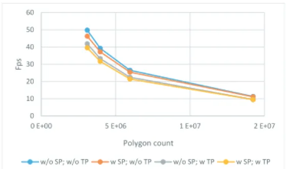
We have measured the computational cost of the last two phases of our method. The second phase is needed only if the user position change, and the third phase has to be executed on each rendering frame. In order to see the linearity of the computational cost of our method in function of the number of vertices, we have com-pared its performances with respect to standard rendering algorithm on different scene complexities: Scene #1 to #4 with respectively 3.088.728, 3.960.142, 5.961.130 and 14.230.254 triangles primi-tives.
Figure 1 shows the framerates achieved by activating or deactivat-ing the various phases of our method (our algorithm is completely inactive when the two tested phases are disabled) and the evolu-tion of framerates with respect to scene complexities. These results prove that the third phase of our algorithm is computed in a linear time of the number of vertices of the 3D scene and is not scene dependent. Its cost is about 15% of the global computational pro-cess in the constraints of our evaluation. The second phase depends only on the number of vertexes of the mesh describing the render-ing surface. This number in constant regardless of the complexity of the scene assessed. Then, its cost decreases with increasing the complexity of the scene.
0 10 20 30 40 50 60
0 E+00 5 E+06 1 E+07 2 E+07
Fp
s
Polygon count
w/o SP; w/o TP w SP; w/o TP w/o SP; w TP w SP; w TP
Figure 1: Graph comparing the framerates obtained by the using the different phases of our method with respect to scenes of different complexity. Results are given on an average of 1.000 frames. SP and TP respectively correspond to the second and third phase of our method.
In order to evaluate the cost of the tessellation step, we have com-pared the results of our method (that uses a geometry and a tessela-tion shader) with a very simple graphical pipeline that just executes a vertex and a fragment shader and an other one that adds a geom-etry shader that does nothing except transferring data. This eval-uation was performed only on the most complex scene (eg Scene #4) and the results are given in table 1. With our implementation, our method reduces the framerate of 55%, considering a rendering pipeline that needs a geometry shader stage. On a side note, the ge-ometry shader stage, with a simple primitives forward, cost about 60% of performance in a rendering pipeline.
Table 1: Comparison of framerates obtained by very simple and standart rendering pipelines (one using a simple vertex shader and a second using a simple geometry shader) and by our algorithm, on Scene #4 on an average of 1.000 frames. SP and TP respectively correspond to the second and third phase of our method.
std. std. w/o SP w SP w/o SP w SP +geo w/o TP w/o TP w TP w TP fps 53.39 20.97 11.33 11.12 9.548 9.507 % 471% 185% 100% 98.1% 84.3% 83.9%
4
Conclusion
We presented in this paper a new real-time method to deform a 3D model displayed on a curved surface so that it is geometrically correctly seen from a user’s viewpoint. This method differs from existing solutions by allowing its application with folding screens or projectors with distorting lenses.
The algorithm proceeds in three stages and the final distortion of the image is parametrized only by the position of the user and by the description of the display surface. The system can therefore be used in combination with projection optics (fisheye for example) or coarse display surfaces, thus limiting the cost of manufacturing immersive systems. These input parameters can also be easily ob-tained and injected in real-time into our system.
References
RASKAR, R., WELCH, G., CUTTS, M., LAKE, A., STESIN, L.,
AND FUCHS, H. 1998. The office of the future: A unified approach to image-based modeling and spatially immersive dis-plays. In Proceedings of the 25th Annual Conference on Com-puter Graphics and Interactive Techniques, ACM, New York, NY, USA, SIGGRAPH ’98, 179–188.