Open Archive TOULOUSE Archive Ouverte (OATAO)
OATAO is an open access repository that collects the work of Toulouse researchers and makes it freely available over the web where possible.
This is an author-deposited version published in : http://oatao.univ-toulouse.fr/
Eprints ID : 19941
To link to this article : DOI: 10.4028/www.scientific.net/SSP.260.69
URL https://doi.org/10.4028/www.scientific.net/SSP.260.69
To cite this version : Jodin, Gurvan and Scheller, Johannes and
Duhayon, Eric and Rouchon, Jean-François and Triantafyllou, Michael S. and Braza, Marianna : An experimental platform for surface embedded
SMAs in morphing applications (2017), Solid State Phenomena vol. 260,
pp. 69-76
Any correspondance concerning this service should be sent to the repository administrator: [email protected]
An experimental platform for surface embedded SMAs in morphing
applications
Gurvan JODIN
1,2,b *, Johannes SCHELLER
2,3,a, Éric DUHAYON
1,c,
Jean-François ROUCHON
1,d, Michael TRIANTAFYLLOU
3,eand Marianna
BRAZA
2,f1LAPLACE, 2, Rue Charles Camichel,- BP 7122, F-31071 Toulouse, France 2IMFT, 1, Rue du professeur Camille Soula, F-31400 Toulouse, France
3MIT, 77 Massachusetts Ave, Cambridge, MA 02139, USA
a[email protected], b[email protected], c[email protected], d[email protected], f[email protected], e[email protected], *corresponding author
Keywords: Morphing, Shape-memory Alloys, Modeling.
Abstract. This article will address the modeling and control of surface embedded shape memory
alloys (SMAs) for the camber modification of a hybrid morphing airfoil. An analytical model will be derived. The results of this models will be discussed and compared to the experiments. The advantages of this modeling approach will be highlighted and alternatives will be briefly revisited. This discussion will figure into the utility of these models in the sizing of a full scale prototype of a SMA actuated active trailing edge of an airfoil. Throughout this article the prototype specifications are detailed and the design choices will be discussed. Performance improvements stemming from the inherent nature of the SMAs will be analyzed. It will be shown in this article that through the use of forced convection the overall cycle time can be reduced.
Introduction
The rigid airfoil geometries of today’s aircrafts are usually the result of a design compromise optimizing the shape only for some parts of flight. Control surfaces are used to adapt the shape for different parts of the mission profile. However, due to the introduction of discontinuities in the shape these control surfaces usually have poor aerodynamic performance and efficiency. The use of deformable or morphing structures has the potential to resolve this issue. Smart-materials hold great potential in achieving the goal of an entirely deformable airfoil structure [1]. The RTRA supported research program DYNAMORPH and the research platform SMARTWING aim at improving the performance of micro-air-vehicles in realistic environments via electro-active morphing. During the course of this project a prototype NACA4412 wing was developed with embedded Shape memory alloys (SMAs) and trailing-edge Macro-fiber composite actuators enabling both large deformations (~10% of the chord) at limited frequency (<1Hz) and small deformations at high frequencies (≤100Hz) [2]. The characteristics of the SMAs, which were actuated using current heating, make it especially suitable to optimize the shape of the wing and to control the flight [3, 4]. The high-frequent but low amplitude piezoelectric technology on the other hand is useful to produce trailing-edge vortex breakdown [5]. Wind-tunnel tests proved the capacities of the design with respect to both the high-frequency, low-amplitude and low-frequency, high-amplitude actuation. However, the tests also showed the need to further characterize the SMA based high-amplitude actuation before moving to a full-scale prototype. To this end a simple model was created resembling one part of the activated airfoil skin.
Different concepts for SMA based camber control can be found in the literature. Elzey et al. [6] used for example a flexible vertebra structure inside of an airfoil in order to generate both variable camber and twist actuation. They successfully demonstrated the bending capacity of their approach (> 50% of the chord length) however their model lacked in rigidity for a real-world application. Similarily, Musloff [7] also achieved significant displacements in his thesis for both 2D and 3D
deformations. Manzo and Garcia [8] constructed a HyperElliptical Cambered Span (HECS) morphing wing capable of achieving around 25% of spanwise bending within ≈ 3 s. The HECS wing shape was linearly discretized allowing the pulley mechanism to act on fixed sections. Windtunnel experiments were carried out using the morphing HECS wing and it was shown that the SMA based mechanism is capable of overcoming significant aerodynamic loads. Pankonien and Friswell [9,10] combined different SMA actuators with a trailing edge Macro Fiber Composite (MFC) actuatued flexure box to achieve a synergistic morphing overcoming the inherent limitations of the different individual materials. They combined a SMA actuated hinge with a flexure box actuated using piezoelectric MFC actuators. Whereas these concepts certainly demonstrated the capacities of the SMA based camber control the design choices led to a limitation of the overall rigidity and actuation frequency of the wing. In order to address these issues our concept integrates the SMAs directly in the surface of the airfoil skin adding to its rigidity. In addition the integration of a forced convection control concept holds to potential to increase the actuators maximum frequency.
This work is developed as follows: in a first part the experimental setup is described, then an analytical model based on the works of Elahini [11] is introduced to estimate the achievable deflection of the system. The experimental results are then shown and compared to the analytical model. Finally the results are discussed and a short conclusion is drawn.
Experimental setup
The experimental setup is illustrated in Figure 1 and the actual experiment is shown in Figure 2. The SMA actuators which are embedded on the surface of the aluminum substrate are activated at different current intensities using a Delta SM 400-AR-8 Power Supply Unit (PSU). The Pulse-Width Modulated (PWM) control signal for both the PSU and the solenoid valve controlling the forced convection is generated using an Arduino Mega 2560 which also collects the strain gauge and temperature measurements. In order to channel the forced convection the embedded SMAs are encapsulated inside of a silicone tube which was selected due to its high temperature resistance as well as its large flexibility. The influence of the silicone tube in the mechanical behavior of the system is considered to be negligible as the thickness of the silicone is smaller than the thickness of the aluminum beam and the Young modulus of the silicone is three orders of magnitude smaller than that of aluminum.
Figure 2: Experiment
The overall displacement is measured using a Mitutoyo linear gage. The measurement synchronization is done using a control PC running Matlab. The strain, voltage and current measurements are acquired at an acquisition frequency of 8 Hz. Due to the limited temporal dynamics of the SMA actuators this low acquisition frequency was estimated to be sufficient. The temperature data was re-sampled using a linear approximation algorithm in order to adapt the measurements to the acquisition frequency of the Arduino.
Analytical model
As previously mentioned, the derived actuator model is based on the phenomenological SMA model developed by Elahini [11]. Due to the fact that phenomenological models are based on easily measured engineering quantities they are favored in engineering applications. In these models the phase-transformation dynamics are described by means of internal variables and the interdependence of these variables is modeled using kinetics equations.
The structural behavior can be estimated using the quasi-static Euler-Bernoulli beam theory modeling the contraction and extension of the SMA actuator as a moment applied at a distance r of the beams neutral layer. In this case the deflection of the beam can be written as
g 2 EI σArL = δ 2 (1)
where δ is the deflection at the linkage between the SMA and the aluminium substrate, σ is the stress in the SMA, A is the SMA’s cross-sectional area, r is the distance between the substrate’s neutral layer and the SMA, L is the length of the substrate from the fixation to the linkage and E and Ig are the substrate’s Young Modulus and area moment of inertia respectively. This allows us to
define an equivalent spring constant keq for the use in the simulation model.
Parameter Value Unit
Radius rSMA 0.5e-3 [m]
SMA length cold 227.5e-3[m]
Density 6500 [kg/m3]
Heat capacity 320 [J/kg°C]
Convection coefficient 120 [W/m2°C]
Resistance 1.1 [Ώ]
Initial/ambient Temperature 20 [°C]
Austenite Young modulus Ea 75e9 [Pa]
Martensite Young modulus Em 28e9 [Pa]
Austenite start temp.As 30 [°C]
Austenite finish temp. Af 75 [°C]
Martensite start temp. Ms 65 [°C]
Martensite finish temp. Mf 25 [°C]
Stress influence coefficient cA 10.3 [Mpa/°C]
Stress influence coefficient cM 10.3 [Mpa/°C]
Substrate thickness 1.5e-3 [m]
Substrate width 33e-3 [m]
Substrate length@SMA interface 165e-3 [m]
Substrate length total 195e-3 [m]
Substrate Young Modulus 69e9 [Pa]
Distance SMA to neutral layer r 2.5e-3 [m] To simulate the prototype’s response due to the SMA’s actuation the previously described structural model will be combined with the phenomenological SMA model as defined by Elahini [11]. The simulation is created using the Matlab/Simulink platform. The block diagram of the combined SMA-structural model is shown in Figure 3. The model forms an algebraic loop as the SMA’s behavior is dependent on both stress and temperature of the actuator. Hence, an iterative solution has to be conducted. The parameters were mainly taken from previous experiments as well as from the literature [11, 12] and can be seen in the table above. The equations describing the heat transfer, the phase transformation, the structural dynamics as well as the relationship between stress, strain and temperature in the SMA will only be briefly repeated below for a thorough explanation please refer to Elahini [11].
Heat transfer. The SMAs are activated using Joule heating. The differential equation governing the
SMA’s heat transfer is given in the Equation below. It combines Joule heating with natural convection. ˙ T= 1 mSMAcp(I 2 R−hcAc(T−T∞)) (2)
Figure 3: Block diagram of the combined SMA-structural model
In this Equation msma is the mass per unit length of the SMA, Ac is the surface area of the wire, I
is the current applied, cp is the specific heat, T is the temperature of the SMA, T∞ is the ambient
temperature and hc is the coefficient of heat convection. For the purpose of this simulation the
resistance R of the wire is assumed constant.
Phase transformation. The phase transformation in the actuator is governed by the martensite
fraction, which has to be known for each instant in time and can be calculated knowing the temperature, the stress and their derivatives. Due to the SMA’s hysteretic nature the description of their phase transformation behavior depends on the previous state of the system. In case the system was previously in the austenite state and is being transformed into the martensite state the transformation is called the forward transformation (see Equation 3). In the inverse case a so called reverse transformation is taking place as described by Equation 4. In both cases the phase transformation is expressed in the form of the time derivative of the martensite fraction ζ.
˙ ζ= ζA−1 2 sin(Am(T− Mf+Bmσ)(AmT˙+Bmσ˙)) (3) ˙ ζ=−ζM 2 sin(Aa(T− As+Baσ)(AaT˙+Baσ˙)) (4)
The variables ζM and ζA represent the martensite fraction at the beginning of the A → M and M → A
transformation respectively, Aa, Am, Ba and Bm can be calculated via Equation 5 knowing the
material properties given in the table below. As, Af are the start and finish temperature of austenite
creation and respectively Ms, Mf are the start and finish temperature of martensite creation.
Variations on temperature linked to stress are represented through cm and cm.
Aa= π As− Af Am= π Ms−Mf Ba= − Aa ca Bm= − Am cm ¿ (5)
Constitutive equation. The relationship between the different variables governing the actuators
behavior is given as Equation 6, where E(ζ) is the Young modulus, ε is the strain, θ is the thermoelastic tensor and Ω(ζ) the transformation tensor.
˙
σ=E(ζ) ˙ϵ+θT˙+Ω(ζ) ˙ζ (6)
It should be kept in mind however that the model assumes a fully detwinned martensite and hence does not model the detwinning process.
Results
After this very brief introduction to the analytical modeling procedure this paper will now focus on the experimental results. A measurement cycle is show in Figure 4. The measurement cycle is repeated every 45 s. The SMAs are heated during 9.8 s at different current intensities and depending on whether cooling via forced convection is used or not a forced convection cooling cycle of 20 s follows the heating. These heating and cooling times are relevant with system dynamics because cooling is slower than heating. The remaining dead times allow the system stabilization over the cycles. In order to compare the different results the measurements are averaged over the active cycle from the beginning of the heating process to the end of the forced convection cooling. The results of this averaging process are shown in Figure 5 for the measurements without forced convection and in Figure 6 for the measurements with forced convection. Comparing these two graphs two things stick out: first as expected the forced significantly improves the cycle time allowing for faster actuation and second the measurements at higher current intensities have a significantly larger standard deviation and a lower maximum achievable deflection. Whereas this
seems counterintuitive it is actually more due to the thermal characteristics of the system than due to the SMAs characteristics.
Figure 4: Averaged displacement vs. time without forced convection. The grey envelope represents one-time the standard deviation averaged over three iterations.
Figure 5: Averaged displacement vs. time with forced convection. The grey envelope represents one-time the standard deviation averaged over three iterations.
Figure 6: Measurement cycle at 6A without forced convection (black: tip displacement, blue cooling cycle (when active) and red heating cycle)
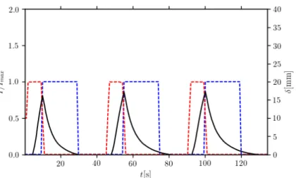
Figure 7: Measurement cycle at 6 A with forced convection (black: tip displacement, blue cooling cycle (when active) and red heating cycle)
Figure 3: Measurement cycle at 4 A (black: tip displacement, blue cooling cycle (when active) and red heating cycle)
Taking a look at the measurement cycle at 6 A with and without forced convection clearly show that even during the relatively long cycle time the SMA is not completely cooled down hence at the beginning of the subsequent cycle not the entire potential of the actuators can be realized. Furthermore, as mentioned in [13] the higher starting temperature might even be counter-productive due to the higher convection at higher temperatures.
Hence, as the time dynamics depend largely on the initial temperature a control systems is necessary in order to implement this control an indicator of the trailing edge deflection is necessary. Whereas different publications either use a force-based [14] or a resistance/inductance [15,16] based approach a strain-gauge position feedback was selected in this paper due to the relative simplicity of implementation as well as the large forces during deformation and the low cost of the sensors. Comparing the averaged measurement values to the averaged measured strain in mV at the output of the amplifier we can see that this type of simple sensor is indeed capable to accurately represent the deformation achieved by the prototype. Figure 9 depicts the displacement vs. strain response of the system for different current intensities. Alternatively one can also choose to compare the measured voltage to the actual strain using the displacement data and the geometry of the clamped free beam, but as the final goal is to control the tip displacement a simple calibration with respect to the tip displacement was selected. Whereas these measurements show a near linear response between the measured tip displacement and the measured voltage it also becomes evident that a saturation occurs once the displacement surpasses 20 mm. In order to avoid this kind of saturation an a priori knowledge of the achievable displacement is necessary. Hence, the next section will briefly compare the achieved displacement during the measurements with the results obtained using the combination of the phenomenological model developed by Elahini [11] and the structural behavior.
Result comparison. Figure 10 shows the comparison of the analytically obtained results and the
experimental results with forced convection. A good correspondence both quantitatively and qualitatively can be observed between the analytical and experimental results. However, whereas during the heating section the simulation results follow the trajectory of the experiment a larger difference can be observed during the cooling portion of the cycle.
In order to account for this behavior a more thorough investigation of the temporal dynamics of the experimental setup is necessary especially regarding the heat exchange with or without forced convection in both a constraint and unconstrained environment. In other words the temperature exchange in the silicone tubes has to be more deeply analyzed. Furthermore for a better understanding of the SMAs properties the variation of the SMA properties during repeated cycles should be taken into account. However, even though the simulation results show room for improvement it is notable that even using this simple simulation model as well as the SMAs
properties obtained from previous experiments and the literature a good correspondence between simulation and measurement can be obtained.
Conclusion
This paper presented a simple experimental prototype for the analysis of the behavior or SMA actuators. The goal was to generate an extensible platform for characterization of surface embedded SMAs allowing to implement different control approaches as well as both forced and natural constraint convection cooling. It was shown that using forced convection the cycle time can be significantly reduced by up to 30 %. Furthermore, due to temperature variation of the SMA during the cycle in the natural constraint convection case the use of forced convection also allows for smaller standard deviation and larger average temperature. Furthermore, a simple low-cost position feedback was introduced in the experimental platform. The simplicity of the linear relationship between displacement and measured strain was highlighted. However, it was shown that care has to be taken as saturation can occur especially at larger values of deflection. Finally, in order to gain an apriori knowledge of the displacement, a combination of a phenomenological SMA model with a simplified structural model was introduced and it was shown that however simple this model a good quantitative and qualitative correspondence during the heating cycle can be obtained. However, it was also shown that due to the added complexity by thermally constraining the actuators a more in-depth analysis of the thermal behavior of the platform is necessary.
In summary this paper showed a simple platform for evaluating different SMA control strategies characterized its deflection behavior both using forced and natural convection and also developed a mean to analyze the platform using a simulation model. This allows in a next step to create and validate different control approaches enabling potentially larger cycle times.
References
[1] Narcis Ursache, Tomas Melin, Askin Isikveren, and Mike Friswell. Morphing Winglets for Aircraft Multi-Phase Improvement. In 7th AIAA ATIO Conf, 2nd CEIAT Int’l Conf on Innov & Integr in Aero Sciences,17th LTA Systems Tech Conf; followed by 2nd TEOS Forum, Aviation Technology, Integration, and Operations (ATIO) Conferences. American Institute of Aeronautics and Astronautics, September 2007. URL http://dx.doi.org/ 10.2514/6.2007-7813.
[2] Johannes Scheller, Gurvan Jodin, Karl-Joseph Rizzo, Jean François Rouchon, Eric Duhayon, Michael Triantafyllou, and Marianna Braza. A combined smart-materials approach for next-generation airfoils. Solid State Phenomena, 2016.
[3] F.T. Calkins, J.H. Mabe, Shape Memory Alloy Based Morphing Aerostructures, Journal of Mechanical Design (2010) Vol. 132 111012
[4] C. Lexcellent, Shape-memory Alloys Handbook, Wiley-ISTE, March 2013, ISBN: 978-1-84821-434-7
[5] Johannes Scheller, Maxime Chinaud, Jean-Francois Rouchon, Eric Duhayon, Sebastien Cazin, Moise Marchal, and Marianna Braza. Trailing-edge dynamics of a morphing NACA0012 aileron at high reynolds number by high-speed PIV. Journal of Fluids and Structures, 55:42 – 51, 2015.
[6] Dana M Elzey, Aarash YN Sofla, and Haydn NG Wadley. A bio-inspired high-authority actuator for shape morphing structures. In Smart structures and materials, pages 92–100. International Society for Optics and Photonics, 2003.
[7] André Musolff. Formgedaechtnislegierungen. PhD thesis, Technische Universitaet Berlin, Uni- versitaetsbibliothek (Diss.-Stelle), 2005.
[8] Justin Manzo and Ephrahim Garcia. Demonstration of an in-situ morphing hyperelliptical cambered span wing mechanism. Smart Materials and Structures, 19(2):025012, 2010. URL http://stacks.iop.org/0964-1726/19/i=2/a=025012.
[9] Pankonien, A.M., Duraisamy, K., Faria, C.T. and Inman, D.J., 2014. Synergistic smart morphing aileron: aero-structural performance analysis. Chapter. doi, 10(2514), p.6.
[10] Pankonien, A.M., 2015. SMART MATERIAL WING MORPHING FOR UNMANNED
AERIAL VEHICLES (Doctoral dissertation, University of Michigan).
[11] Mohammad Elahinia. Effect of system dynamics on shape memory alloy behavior and control. PhD thesis, Virginia Tech, 2004.
[12] Jérôme Duval. Conception et mise en oeuvre d’un système d’actionneurs AMF répartis pour le contrôle de forme électroactif de voilures aéronautiques. PhD thesis, Institut National Polytechnique de Toulouse, 2005.
[13] J. Jayender, R. V. Patel, S. Nikumb and M. Ostojic, "Modelling and gain scheduled control of shape memory alloy actuators," Proceedings of 2005 IEEE Conference on Control Applications, 2005. CCA 2005., Toronto, Ont., 2005, pp. 767-772.
[14] Featherstone, Roy, and Yee Harn Teh. "Improving the speed of shape memory alloy actuators by faster electrical heating." Proceedings of the Ninth International Symposium on Experimental Robotics. 2004.
[15] Kim, Hongjip, et al. "Sensorless displacement estimation of a shape memory alloy coil spring actuator using inductance." Smart Materials and Structures 22.2 (2012): 025001.
[16] Ma, N., G. Song, and H. J. Lee. "Position control of shape memory alloy actuators with internal electrical resistance feedback using neural networks." Smart materials and structures 13.4 (2004): 777.