Gabriela Celani, David M. Sperling and Juarez M.S. Franco (Eds.): The Next City: 16th International Conference CAAD Futures 2015, pp. 226-238, 2015. © Biblioteca Central Cesar Lattes 2015.
optimization
Mohamed-Anis Gallas1,2, Vincent Delfosse2 1 School of Architecture of Nancy
2 University of Liège
{ma.gallas, vincent.delfosse}@ulg.ac.be
Abstract. This paper focuses on sketch-based and parametric modeling as two externalization devices used in architectural design practice. The first part of this paper addresses features and ability of these externalization tools to support design activities during the early design steps. The second part proposes an association process of a sketch-based modeling tool (SketSha-Archi®) and a
parametric modeling tool (Grasshopper®) to create an advanced process for
daylight optimization. The process aimed to associate the hand-sketching freedom with the precise exploration functions of digital tools (parametric modeling and evaluation tools).
Keywords: Sketch-based modeling; parametric modeling; early design stages; daylight simulation; optimization process.
1
Parametric modeling in architectural design
Parametric modeling is one of the digital modeling methods integrated in architectural design praxis. The generated models are controlled by parameters that characterize and control the most pertinent features of the modeled object and the design context. Parameters can describe geometric, performance, structural, material, social, urban and environmental features. The designer can generate different spatial and technical configurations based on the same parametric model. Parameters are instantiated by interchangeable values generating these objects.
The designer controls the value attribution process and try to find the best response to the design intentions and constraints. Optimization algorithms can be used to control the parameters instantiation process. The designer defines a target values describing his intentions (features, performance) translated in measurable values and optimization algorithms controls the value attribution process. These algorithms select the best parameters values generating the most pertinent configurations (verifying the target values). Evaluation devices linked to the parametric models to compute the performance level of the generated solutions [1], [2]. The evaluation devices concern sensitive features (atmosphere) and physical ones (daylighting, energetic and
structural behavior). The association of parametric model, evaluation devices and optimization algorithms creates an iterative process that helps designers to operate complex research and exploration design activities. This kind of process contrasts with the static behavior of the classic modeling methods that are used to create one instantiated model. A fixed statement and a complex modification process characterize the modeled objects. In contrast, parametric modeling methods are used to define the structure of the designed object and the most pertinent controlling parameters in order to generate different configurations. In fact, the dynamic features of the parametric modeling methods offer more exploration potential than other digital modeling media [3].
As explained before, parametric modeling methods define the structure of the modeled object and not a fixed status. Object status will change depending on values attributed to parameters. A parametric model easily integrates transformation and evolution activities. During the early design steps, designers try to explore possibilities define the most important project features. At the beginnings, these features are fuzzy and hardy measurable due to the lack of design information. They progressively evolve to be more precise thanks to the iterative process of propose, evaluate and select activities. These features make parametric modeling methods more suitable for early design activities [4].
Parametric modeling is an evolutionary process. It can be transformed and enriched progressively as design process progresses. The designer can transform the parametric model structure by integrating new parameters, new features and more functions. The parametric model can be linked to more detailed ones adding new functions resulting from more advanced design steps. The following example shows how the designer used a parametric modeling tool (Grasshopper®) to design the lofted surface creating
the outside skin of the project (early design steps) using simple curves. The model has been improved to integrate the skin materialization process using two modular components types (advanced design steps). The modular components are dispatched on the created surface through a distribution condition. The designer used the same model to integrate his early and advanced design intentions and constraints.
Fig. 1. Evolution of the parametric model [5]
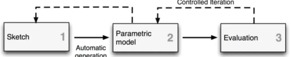
During the early design steps, designers spend from 5% to 20% of their designing time to create the parametric model. The duration of the modeling and transformation time task depends on the knowledge level from of the parametric modeling tools. Expert users reduce duration required for the definition of their parametric model definition and allow more time to perform design activities. By contrast, novice users of parametric modeling tools consider modeling activity as an additive design constraint that constitutes an additive cognitive constraint. This constraint can delay the design task achievement.
Fig. 2. Parametric modeling process
We consider parametric modeling as an advanced externalization activity that respects the early design steps features. This activity needs to be improved in order ease the parametric modeling activities. Parametric model creation must respect the designer’s praxis by generating design media in few laps of time. Support design models (parametric models) must be easily transformable and particularly for conceptual steps.
2
Sketch based modeling in architectural design
2.1 Sketching in architecture
Sketching, as a representation tool, help designers to externalize their intentions and ideas and to address a first step of graphical conceptualization for architectural solution [6]. Sketching is considered as a tool to simplify reality, illustrate intentions and going to the most pertinent concepts [7]. They help the designer to progressively materialize design problems and reduce their complexity. Sketching helps designer to quickly produce and modify representation of the design problem and solutions [8], [9]. The use of sketching creates an iterative process of design integrating “propose”, “evaluate” and “modify” activities. The iterative features of this process ensure the flexibility of the modification and appropriation activities characterizing early architectural design steps [10]. The flexible structure of sketching generates multiple interpretations of the externalized ideas and solutions through a continuous reflection process [8].
The precision level of the representations and the models increases and accompanies the evolution of the design activities. Written data and conceptual sketches and models are used during the early design steps characterized by the lack or the inaccuracy of the design information. Detailed representations, physical and digital models are usually used during the last steps of the design process where design information is available and precise. Representation tools like sketching used at the early design steps as sketching enhance the designer freedom. They allow many options and opportunities for how they can be read and understood [11].
By contrast, the use of digital modeling tools during conceptual design steps reduces the designer freedom. This limitation is due to the use of new artifacts
(screen, mouse), new gestures, the need of detailed design information and a longer realization time. Despite this limitation, digital design tools, initially destined to production steps, are now used in the early steps. These steps are characterized by research and exploration design activities. The use of production design tools during early design steps tends to reduce the designer creativity and to impoverish the design. The designer is influenced by the tools functions during the decisive steps of the project elaboration [8]
2.2 Sketch-based modeling
This observation has led to update sketch-based modeling technics integrating gestures in modeling process. They associate free hand-sketching functions to digital modeling ones. This technic was initiated since the sixties by Ivan Sutherland that develop the Sketchpad device [12]. This device proposes a graphical freehand interface to draw geometries. It aims to associate the benefits of hand drawing to the digital tools functions.
Since 2007, the LUCID-ULg has been developing and using the SketSha® software
(for Sketch Sharing) [13]. This application supports sketch-based, synchronous and distant collaboration. Based on the analogy of a real meeting, SketSha® offers a shared
working space, where all participants can import and annotate any design documents (image, pdf, dxf or screen-captures). This application has been discussed in many articles [14],[15], [16]. The figure below shows an example of a SketSha® project.
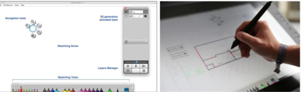
Fig. 3. SketSha® interface and use
Sketches are also used to generate 3D models. They are used as basic information for complex 3D modeling activities. They allow user to draw free hand sketches and to translate them to tangible 3D models using digital pens as communication and expression artifacts. The generated models can be used for representation purposes or can be integrated to the evaluation processes. The translation of 2D sketches to 3D models is achieved in three steps; a sketch analysis step, a synthesis step and an interpretation step. This process is limited by the need of precise knowledge about the design context and the used representation rules.
An alternative solution was integrated in SketSha®. An architecture-specific
version has been developed. It allows the generation of an architectural 3D model, based on some explicit drawing conventions used in the sketches. It uses dedicated pens to describe walls, windows and doors. These elements will be extruded vertically in order to produce a 3D model. The figure below shows an example of some mix of interpreted and non-interpreted 2D layers and the resulting 3D model. Tagging the concerned layer (red tag on the layer name) activates the 3D interpretation process. We associate a semantic dimension to the sketching tools (pens) describing the most important parts of project as wall, bulkhead, windows and materials. We need also this information during the evaluation process of the project daylight behavior. This process simplifies the analysis step and enhances the adaptation ability to different design context and users.
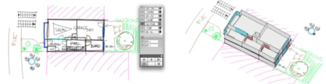
Fig. 4. Multiple layers of 2D sketches and the resulting 3D model
The tool supports multiple floors and the user can control the heights of the different floors, doors and windows on a per-floor basis. SketSha-Achi® also allows
some more complex extrusion capabilities, useful to express non-flat roofs for instance. One of the sketching pens is dedicated to design draw and characterizes the roof edges. The roof generation tool analysis the drawn edges to propose a 3D interpretation. The figure below shows the roof edges drawing process and the generated result of a multiple sloped roof.
Fig. 5. An example of complex extrusions producing a roof
SketSha-Archi® allows many layers to be placed on top of each other and
will be part of the 3D model, and which layers are just pure 2D annotations. This mixing of interpreted and non-interpreted layers enables a two-step process for a design iteration. The user can freely explore his design ideas with non-interpreted sketches. Then, when the project reaches the required level of maturity, the user can create the interpreted layers, and overlay his previous sketches with the interpreted pens. The user can decide whether the 2D sketches are displayed in the 3D view or not. The generated model must be integrated in the design process to develop and enhance the performance and features of the proposed solutions. It must be used as a base line model to operate exploration and optimization activities.
The generated models are unique with fixed characteristics. The modification process of the generated models needs a major intervention of the designer (the use of modeling tools to modify the model features). This cognitive load reduces the possibilities to integrate the generated models in an iterative optimization and evaluation process.
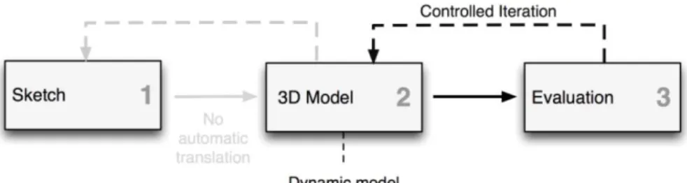
Fig. 6. Skeching, 3D model generation and evaluation process
3
Association of sketch-based and parametric modeling
3.1 Association process
We propose a design aid strategy to help the designer to externalize his ideas and to explore potential solutions during early stages. The method aims to keep design freedom characterizing sketching steps and to propose a solution to associate complex activities (evaluation, modification and optimization) to these steps. This strategy associates the interactivity of sketch modeling methods and the exploration ability offered by the parametric ones. We consider them as two externalization devices able to support design activities during the early steps of design process operating at different levels of accuracy. Sketch-based modeling methods will be used to materialize ideas (free hand sketching) and to translate them to 3D dynamic models (translate sketches to parametric models) able to operate exploration and evaluation activities. The association of the sketch-based and the parametric modeling methods
creates an iterative process of “propose, evaluate and modify” activities. The designer uses this process to operate an optimized process of architectural and technical solutions generation verifying a given targets.
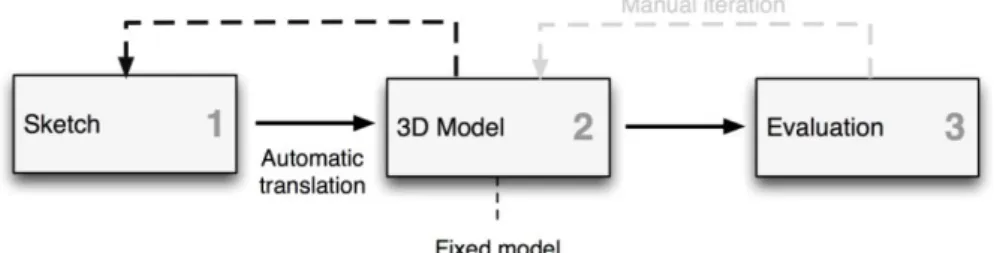
Fig. 7. Association process of sketch-based and parametric modeling methods for evaluation and optimization purposes
3.2 Advanced sketch based modeling process
Evaluation and generation activities need detailed design information. These information concern the project features participating the optimization process. For daylight behavior optimization process we need detailed information about project as wall reflection factor or aperture transmission one. We propose to associate these semantic information to the drawn sketches. Designer can characterizes the designed project by a drawing colored strokes on the drawn object. These strokes will be interpreted as extra-information to be transferred to the parametric tool. The exact semantic of this information is not embedded in SketSha Archi®, but is left to the user
and to the parametric tool itself. Designer can change the signification of the different tags to associate them to new features or new king of materials depending on design context.
Fig. 8. Illustration of some added information to the building description
The figure below illustrates the possibility to add extra information to the building. The window in blue is tagged with a green stroke, when the wall itself is tagged by a
single purple stroke. The designer can decide on the semantic signification of these tags. For instance, the green tags represent 10% of opacity. The user can then adapt the level of opacity of this window by adding or removing green strokes, thus changing the properties of its element without leaving the 2D graphical interface.
A specific file format has been developed for exchanging data between the sketching and parametric modeling tool (integrating evaluation and optimization devices). It is a text-based file in order to ease its parsing in the parametric-tool side. It contains all the information of the geometric 3D model, the semantic of the elements (wall, doors, etc), as well the tag information. The export file is structured by keywords describing the geometric features of the exported project and the associated annotations. Keywords describe the project from a global scale to a detailed one. It detail the number of floors composing the drawn project, the height, the wall count and the created space count for each identified floor. The keywords concern also the geometric features of the walls, the windows and the doors composing the different spaces. We mean by geometric features the number, the type of segments used to represent these objects. The keywords are also used to identify and describe the design information associated to the project objects and particular the tags count and types.
For instance, for the top-most wall in figure 11, the full wall is described with both the green and purple tags. Then its 3 sub-parts are described, as 2 walls and 1 window, each coming with their specific tags.
Floor_count-1 Floor-0 Height-3 Wall_count-4 Space_count-1 Wall-0; Segment_count-1 Segment w.Annotation_count-1 Annotation_magenta Polyline; w.Point_count-4 25521.44,24640.05 25523.0,24661.0 25525.0,24896.0 25503.66,25475.05 Wall 1; Segment_count-3 Segment; w.Annotation_count-1 Annotation_magenta
Polyline;
w.Point_count-3 25503.66,25475.05 25296.0,25485.0 25225.0,25483.58
Fig. 9. Example of exported file from SketSha Archi® describing a sketch
3.3 From sketches to parametric model
The generation of the parametric model and the evaluation process are implemented in a Grasshopper® definition. The generated 3D model integrates the project volumes,
opening faces and windows. We create a Grasshopper® definition to read the export
file generated from SketSha Archi®. It retrieves the information used to create the
parametric model components (walls, apertures) and their features (roof height, aperture dimension). These information are integrated in Grasshopper® components
that generated the different geometries (polygonal surfaces).
Tags are also used to identify annotations associated to the model components and translate them into features characterizing the generated model (aperture and wall material).
Fig. 10. Parametric model generation
The designer can modify the feature of the generated model. We associate four parameters to “roof”, “window” and “orientation” keywords. Designer can attributes new values to these parameters modifying the generated model features. By this way,
we create two modification scales. The fist one (global scale) concerns the sketches initially used to generate the 3D model and the second one (more local) concerns the model components.
Fig. 11. Parametric model modification features
The parametric model is used to initiate an optimization process of the quantitative and the qualitative features of the designed project. This process integrates the plugin
Diva For Rhino® [17] that links Grasshopper® to the daylight simulation software
Radiance®. The optimization algorithms control the parameters value attribution process and operate to find a target defined by the designer. We use an image (representing daylight effects) selection process to identify and characterize the designer daylight intentions. The characterization (quantitative one) of the identified daylight intentions constitutes the target function used to operate the optimization process. This identification and characterization process is a result of my precedent research work [18]. We use Galapagos®as the optimization algorithm associated to
the Grasshopper® and Diva For Rhino® as simulation device. We define the number
of simulation nodes to reduce the optimization process duration to less than 10 minutes. This duration respects the design activities and process features.
The parametric model is generated from digital sketches in a short amount of time. The automatic generation process helps the designer to simplify the parametric modeling activity and to quickly initiate an optimization process. These features allow the integration of optimization activities during the early design steps. The user can use his sketches to explore other spatial configurations and solutions using the same generated parametric model. The parametric model can be modified and updated to integrate more precise design information or parameters values (other materials, aperture features).
Fig. 12. Evaluation and optimization process
4
Conclusion
This paper presents a design method integrating sketch-based and parametric modeling tools for daylight optimization during early design steps. We consider sketch-based devices as a first externalization method respecting the designers praxis. Parametric modeling devices are considered as advanced externalization method integrating precise and controlled optimization activities.
The design method was implemented using a sketch-based modeling tool (SketSha Archi) and a parametric tool (Grasshopper® definition) integrating a simulation tool
(Diva For Rhino®) and an optimization algorithm (Galapagos®). Experimentation results shows that the process can support the design activities during the early design steps but needs some improvements. We are now working on the generation of complex parametric models and the ability to integrate more designer intentions and design constraints.
References
1. Aish, R. and R. Woodbury. 2005. Multi-level Interaction in Parametric Design. In SmartGraphics, 5th International Symposium, SG2005, Lecture Notes in Computer Science 3638, eds. Andreas Butz, Brian Fisher, Antonio Krüger and Patrick Oliver, 151-162. Berlin: Springer.
2. Ander, R. and R. Mendgen. 1996. Modelling with constraints: theoretical foundation and application. Computer-Aided Design 28(3):155-168.
3. Sanguinetti, P., & Abdelmohsen, S. (2007). On the Strategic Integration of Sketching and Parametric Modeling in Conceptual Design. In Expanding Bodies: Art “Cities” Environment. Presented at the Association for Computer Aided Design in Architecture (ACADIA), alifax, Nova Scotia, Canada, pp. 242–249.
4. Sanguinetti, P., & Kraus, C. (2011). Thinking in Parametric Phenomenology. In Parametricism (SPC) ACADIA Regional 2011 Conference Proceedings. University of Nebraska, Lincoln, Nebraska, USA, pp. 39–48.
5. Miller. N (2011). The Hangzhou Tennis Center: A Case Study in Integrated Parametric Design. In Parametricism (SPC) ACADIA Regional 2011 Conference Proceedings. University of Nebraska, Lincoln, Nebraska, USA.
6. Conan, M. (1990). Concevoir un projet d’architecture. L’Harmattan. 7. Pascale, B. (2008). Jacques Ripault Carnets de Croquis 2. A Tempera. 8. Schon, D (1983) The reflective practitioner Temple-Smith, London
9. Cross, N (1999) Natural intelligence in design Design Studies Vol 20 No 1 pp 25e39 10. Lawson, B (1990) How designers think: the design process demystified (2nd edn)
Butterworth Architecture, London
11. Wiggins, G. E. (1989). Methodology in architectural design (Thesis). Massachusetts Institute of Technology. Retrieved from http://dspace.mit.edu/handle/1721.1/14498
12. Sutherland, I. E. (1964). Sketch pad a man-machine graphical communication system (pp. 6.329–6.346). ACM Press.
13. SketSha, http://www.sketsha.be, 2011
14. Stéphane Safin, Roland Juchmes, Pierre Leclercq (2012), Use of graphical modility in a collaborative design distant setting, Proceedings of the 10th International Conference on theDesign of Cooperative System.
15. Stéphane Safin, Vincent Delfosse, Pierre Leclercq (2008), Mixed Reality Prototypes to Support Early Creative Design, The Engineering of Mixed Reality Systems, Springer, 2010 16. Catherine Elsen, Pierre Leclercq, "SketSha" or the sketch power to support collaborative
design, Lecture Notes in Computer Science, Springer.
17. Jakubiec, J. A., Reinhart, C. F. (2011). DIVA 2.0: Integrating daylight and thermal simulations using Rhinoceros 3D, Daysim and EnergyPlus. Presented at the Building Simulation, Sydney (Australia).
18. Gallas, M.A, Halin, G (2013). DaylightGen: from daylight intentions to architectural solutions. The impleme. ntation and the experimentation of a generative and parametric design tool. eCAADe 2013, The 31th International Conference of the Education and Research in Computer Aided Architectural Design in Europe, September 18th-20th 2013, Faculty of Architecture, Delft University of Technology, Delft, the Netherlands.
![Fig. 1. Evolution of the parametric model [5]](https://thumb-eu.123doks.com/thumbv2/123doknet/6175285.158765/3.892.209.694.243.795/fig-evolution-parametric-model.webp)