HAL Id: hal-02991525
https://hal.archives-ouvertes.fr/hal-02991525
Submitted on 15 Nov 2020
HAL is a multi-disciplinary open access
archive for the deposit and dissemination of
sci-entific research documents, whether they are
pub-lished or not. The documents may come from
teaching and research institutions in France or
abroad, or from public or private research centers.
L’archive ouverte pluridisciplinaire HAL, est
destinée au dépôt et à la diffusion de documents
scientifiques de niveau recherche, publiés ou non,
émanant des établissements d’enseignement et de
recherche français ou étrangers, des laboratoires
publics ou privés.
∼2.3 µ m: Effect of
Energy-Transfer Upconversion
Pavel Loiko, Remi Soulard, Lauren Guillemot, Gurvan Brasse, Jean-Louis
Doualan, Alain Braud, Aleksey Tyazhev, Ammar Hideur, Frédéric Druon,
Patrice Camy
To cite this version:
Pavel Loiko, Remi Soulard, Lauren Guillemot, Gurvan Brasse, Jean-Louis Doualan, et al.. Efficient
Tm:LiYF4 Lasers at
∼2.3 µ m: Effect of Energy-Transfer Upconversion. IEEE Journal of Quantum
Electronics, Institute of Electrical and Electronics Engineers, 2019, 55 (6), �10.1109/jqe.2019.2943477�.
�hal-02991525�
Abstract—The 3H4 → 3H5 transition of Thulium ions (Tm3+), which features laser emission at ~2.3 µm is studied in details. We revise the conditions for efficient laser operation using a rate-equation model accounting for the ground-state bleaching, cross-relaxation and energy-transfer upconversion (ETU). We show that ETU has a crucial role in reaching more than unity pump quantum efficiency (QY) for ~2.3 µm Tm lasers based on highly-doped crystals. A Ti:Sapphire pumped quasi-continuous-wave 3.5 at.% Tm:LiYF4 laser generated 0.73 W at 2306 nm with a record-high slope efficiency of 47.3% (versus the absorbed pump power) featuring a QY of 1.27. Diode-pumping of this crystal yielded a peak output power of >2 W. The first 2.3 µm Tm waveguide laser is also reported based on Tm:LiYF4 epitaxial layers with even higher doping of 6.2 at.% generating 0.23 W with a slope efficiency of 19.8%. The spectroscopic properties of Tm:LiYF4 relevant for the ~2.3 µm laser operation are revised as well.
Index Terms—Solid-state lasers, laser transitions,
mid-infrared, spectroscopy.
I. INTRODUCTION
OWADAYS,there is a great demand of mid-infrared (MIR) laser sources emitting at wavelengths around ~2.3 µm. In this spectral range, the absorption lines of such atmospheric pollutants as hydrogen fluoride (HF), carbon monoxide (CO), methane (CH4) and formaldehyde (H2CO) are located [1-5].
Such MIR emission falls into the 2.0–2.4 µm atmospheric window, the so-called K band. Thus, wavelength-tunable ~2.3 µm lasers are used for gas sensing in the atmosphere [1,3,5] or
Manuscript received February 1, 2019. This work was supported by French Agence Nationale de la Recherche (ANR) through the LabEx EMC3 project FAST-MIR; European Community funds FEDER and the Normandy region.
(Corresponding author: Patrice Camy.)
R. Soulard, P. Loiko, L. Guillemot, G. Brasse, J.-L. Doulan, A. Braud and P. Camy are with the Centre de recherche sur les Ions, les Matériaux et la Photonique (CIMAP), UMR 6252 CEA-CNRS-ENSICAEN, Université de Caen, 6 Boulevard du Maréchal Juin, 14050 Caen Cedex 4, France (e-mail: [email protected]; [email protected]; [email protected]; [email protected]; [email protected]; alain.braud@ ensicaen.fr; [email protected]).
A. Tyazhev and A. Hideur are with CORIA UMR6614, CNRS-INSA-Université de Rouen, Normandie CNRS-INSA-Université, Avenue de l’université, BP. 12, 76801 Saint Etienne du Rouvray, France (e-mail: [email protected]; [email protected]).
B. Guichardaz is with the FEMTO-ST Institute, Route de Gray, 25030 Besançon Cedex, France (e-mail: [email protected]).
F. Druon is with the Laboratoire Charles Fabry, 2 avenue Augustin Fresnel 91127 Palaiseau, France (e-mail: [email protected]).
during the combustion experiments [2]. They are also relevant for non-invasive glucose measurements [6].
There exist several possibilities to achieve laser emission at ~2.3 µm. The first option is to use transition-metal-ion doped II-VI materials, i.e., Cr2+:ZnS or Cr2+:ZnSe [7,8]. However,
the synthesis of zinc chalcogenide crystals and ceramics with high optical quality is complicated and, moreover, these gain media cannot be directly pumped by laser diodes. The second option is the use of semiconductor materials (GaInAs on InP or GaInAsSb on GaSb) [9-12], in Vertical-Cavity Surface-Emitting Lasers (VCSELs) with a sophisticated design.
An easier way to generate the ~2.3 µm laser emission is to use optically-pumped dielectric materials (crystals or glasses) doped with trivalent Thulium ions (Tm3+). Tm3+ possesses an electronic configuration of [Xe]4f12 and it is well-known for its near-infrared (NIR) laser emission at ~2 µm due to the 3F4
→ 3H
6 transition [13], see Fig. 1(a). Tm3+-doped materials are
typically pumped at ~0.8 µm (to the 3H
4 level), e.g., using
Ti:Sapphire lasers or high-power AlGaAs laser diodes. There exist a very efficient cross-relaxation (CR) process for adjacent Tm3+ ions which promotes this pumping scheme,
Tm1(3H4) + Tm2(3H6) → Tm1(3F4) + Tm2(3F4). Thus, the pump
quantum efficiency may approach 2 leading to reduced heat loading and high laser slope efficiency well exceeding the Stokes limit [14].
Fig. 1. (a) Simplified scheme of energy levels of Tm3+ ions in LiYF 4: blue
and red arrows – pump and laser transitions, respectively, black arrows – radiative relaxation, green arrows - non-radiative relaxation (NR), cross-relaxation (CR), energy-transfer upconversion (ETU), energy migration (EM); (b) equivalent scheme of energy levels for construction of rate equations. The Stark splitting for Tm3+ ions is according to [15].
The ~2.3 µm MIR emission is related to less common Tm3+
transition, 3H
4 → 3H5 [16], Fig. 1(a). Due to the small energy
gap of about 2000 cm-1 between the lower laser level (3H 5) and
Efficient Tm:LiYF
4
Lasers at ~2.3 µm: Effect of
Energy-Transfer Upconversion
Pavel Loiko, Rémi Soulard, Lauren Guillemot, Gurvan Brasse, Jean-Louis Doulan, Alain Braud,
Aleksey Tyazhev, Ammar Hideur, Blandine Guichardaz, Frédéric Druon and Patrice Camy
the lower-lying excited-state (3F
4), the former one is rapidly
depopulated by the multi-phonon non-radiative (NR) relaxation, so that the ions are accumulated in the 3F4
metastable multiplet [17]. Thus, the ~2.3 µm laser transition representing a quasi-four-level laser scheme is not self-terminating.
A summary of bulk ~2.3 µm free-running and continuous-wave (CW) Tm lasers reported to date is shown in Table I. In early papers [16,18], pulsed laser operation has been achieved in Tm,Cr:Y3Al5O12 and Tm,Cr:YAlO3 oxide crystals (the Cr3+
codoping enhanced the pump absorption efficiency) under flashlamp-pumping.
Further studies were performed with laser-pumping (using Alexandrite [19] and Ti:Sapphire [17,20] lasers) allowing for selective excitation to the 3H4 state. As gain materials, Tm3+
-doped fluoride LiYF4 and oxide Y3Al5O12 or Lu3Al5O12
crystals were employed. A Ti:Sapphire pumped Tm:LiYF4
laser generated 0.22 W at 2.30 µm with a slope efficiency of 15 % (versus the incident pump power, with 80% absorption) and a continuous tuning of the emission wavelength from 2.20 to 2.46 µm was also demonstrated [18]. Slightly higher slope efficiency was reported [20] (Table I) whilst still being lower than the Stokes efficiency for the 3H
4 → 3H5 laser transition
(~34%).
The suitability of Yb3+,Tm3+-codoped fluoride crystals for
laser emission at ~2.3 µm was analyzed theoretically in [21]. Regarding diode-pumping which may potentially allow for power scaling, the key results were achieved for Yb3+,Tm3+
-codoped LiYF4 crystals [22-24]. Here, the Yb3+ ions were
introduced to enhance the absorption efficiency when using InGaAs laser diodes emitting at ~0.98 µm. A diode-pumped Yb,Tm:LiYF4 laser generated 0.45 W at 2.30-2.32 µm
(broadband emission) with a slope efficiency of 18% (with 65% pump absorption) [22].
TABLE I
SUMMARY* OF ~2.3µM LASERS REPORTED SO FAR
Crystal Pump** λP, µm Pout, W Eout, mJ λL, µm η, % Ref. Tm,Cr:Y3Al5O12 FL – – – 2.32 – [16] FL – – 150 2.32 0.4 [18] Tm,Cr:YAlO3 FL – – 12 2.27, 2.35 – [16] Tm:LiYF4 AL 0.79 – 1.1 2.29–2.31 18 [19] TS 0.78 0.22 – 2.30 15 [17] TS 0.78 0.15 – 2.31 19 [20] Tm:Y3Al5O12 AL 0.79 – 1.1 2.30–2.34 14 [19] Tm:Lu3Al5O12 AL 0.79 1.0 ~2.3 13 [19] Yb,Tm:LiYF4 LD 0.98 0.45 – 2.30–2.32 18 [22] LD 0.69+ 0.96 0.62 – ~2.3 7.9 [23] Tm,Ho:LiYF4 LD 0.79 0.002 – 2.08+2.31 42 *** [24] Tm:LiYF4 LD 0.79 0.01 – ~2.3 10 [25]
*λP – pump wavelength, Pout and Eout – output power and pulse energy,
respectively, λL – laser wavelength, η – slope efficiency. **Pumping: FL –
flashlamp; AL – Alexandrite laser; TS – Ti:Sapphire laser, LD – laser diode. ***For both Tm3+ and Ho3+ emissions.
Pulsed laser operation in the passively Q-switched (PQS) [20] and mode-locked (ML) [26,27] regimes has been also achieved for ~2.3 µm bulk Tm lasers. The first ML ~2.3 µm bulk Tm laser using SEmiconductor Saturable Absorber
Mirror (SESAM) generated 94 ps pulses at 2305.9 nm [27]. Shorter ML pulses of 514 fs (emission bandwidth of >15 nm) were achieved based on Kerr-lens mode-locking [26].
There also exist reports about ~2.3 µm Tm fiber lasers [28-32].
For the Tm3+ ions, the lifetime of the 3H
4 state (upper laser
level for the ~2.3 µm transition) is subjected to quenching by different processes. Among them, multi-phonon NR relaxation which is strongly host-dependent, CR which raises fast with Tm3+ doping and energy-migration (EM) which is relevant for
certain materials and high Tm3+ doping levels, Fig. 1(a). Thus,
from the host-material-wise point of view, low-phonon hosts are preferred for ~2.3 µm lasers such as fluorides.
Among fluoride crystals, tetragonal lithium yttrium fluoride (LiYF4) has been considered for ~2.3 µm lasers [17,19,20].
This crystal is well-known for Tm3+ doping and it provides
highly efficient laser operation at the 3F
4 → 3H6 transition
[33,34]. LiYF4 features low maximum phonon energy, hνph =
446 cm-1 [35] diminishing the NR relaxation, good thermo-mechanical properties (the thermal conductivity is about 5–7 Wm-1K-1) [36] opening the ways for power scaling, low refractive index, broad transparency range and large range of available Tm3+ concentrations [34]. The growth of LiYF
4
crystals by Czochralski method is well-developed [37]. When doped with Tm3+ ions, the LiYF
4 crystals provide long (in the
ms-range) lifetimes of the excited-states (3H
4 and 3F4) and
anisotropic emission properties [38] leading to polarized laser output.
Now, let us consider the effect Tm3+ doping level on the ~2.3 µm laser performance. At a glance, it should be kept low so that the shortening of the upper laser level (3H4) lifetime by
CR is weak. In the opposite case, the laser threshold will raise significantly. However, the doping cannot be too low to keep a reasonable pump absorption efficiency. As a result of such considerations, ~2.3 µm Tm:LiYF4 lasers reported to date
were based on crystals with low doping levels, about 1–2 at.% [17,19,20,25].
In the present paper, we aimed to investigate the effect of two relevant energy-transfer processes, namely, the CR and energy-transfer upconversion (ETU), Tm1(3F4) + Tm2(3F4) →
Tm1(3H6) + Tm2(3H4) [39], on the performance of ~2.3 µm
Tm:LiYF4 lasers. As a result, we prove that the ETU can play
a positive role in highly Tm3+-doped crystals leading to the
laser slope efficiencies exceeding the Stokes limit (or, in other words, to pump quantum efficiency of more than unity).
II. SPECTROSCOPY OF TM:LIYF4
A. Crystal growth
Bulk Tm:LiYF4 crystals used for spectroscopic studies were
grown by the Czochralski (Cz) method using undoped [001]-oriented LiYF4 seeds. The growth temperature was ~780 °C.
The Tm3+ doping concentration was 0.5, 1, 3, 5 and 10 at.%. Tetragonal LiYF4 crystal (space group C64h – I41a) is optically
uniaxial (negative) and its optical axis is parallel to the crystallographic c-axis. The samples were thus oriented with respect to the a and c axes.
B. 3H
4→3H5 Tm3+ transition
The stimulated-emission (SE) cross-sections, σSE, for the 3H
4 → 3H5 transition of Tm3+ ions in LiYF4 were calculated
using the Füchtbauer–Ladenburg (F-L) formula [40]: . dλ ) λ ( ) ' ( ) λ ( 3 8 λ ) λ ( , , 3rad 2 5 SE
∑∫
= = α π σ λ β τ π σ j j j j i W JJ W c n (1)Here, W(λ) is the measured luminescence spectrum, n is the refractive index (no = 1.440 and ne = 1.462) [41], c is the speed
of light, τ3rad is the radiative lifetime of the emitting state (3H4),
β(JJ') is the luminescence branching ratio. The index j
indicates the light polarization. The transition 3H
4 → 3H5 is of
both electric dipole (ED) and magnetic dipole (MD, ΔJ = 0, ±1) nature. Thus, for a uniaxial crystal, three principal light polarizations can be defined, i.e., σ (E ⊥ c, k ⊥ c), π (E || c, k ⊥ c) and α (E ⊥ c, k || c) [42]. Here, E and k are the light polarization and propagation direction, respectively. Note that for purely ED transitions, π ≡ α. This difference originates from the dependence of MD transition probability on the orientation of H vector. A 1 at.% Tm:LiYF4 crystal was used
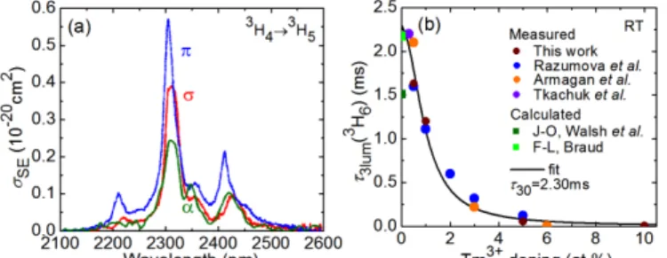
to measure W(λ). The results on σSE are shown in Fig. 2(a).
The maximum σSE = 0.57×10⁻²⁰ cm2 at 2305 nm for
π-polarization. The bandwidth (FWHM) for the corresponding emission peak is 25.8 nm.
Fig. 2. Spectroscopy of the 3H
4 → 3H5 transition of Tm3+ ions in LiYF4: (a)
stimulated-emission (SE) cross-sections for the π, σ and α light polarizations; (b) luminescence lifetime of the 3H
4 state τ3lum vs. the Tm3+ doping
concentration: symbols – experimental data, curve – their fit with Eqs. (2)-(3),
τ30 is the intrinsic lifetime. All results correspond to room temperature.
For the 3H
4 → 3H5 transition, the upper laser level is 3H4.
The results on the 3H
4 luminescence lifetimes τ3lum obtained in
the present work and in the previous papers [38,43-46] are summarized in Fig. 2(b). The τ3lum decreases with the Tm3+
doping due to the CR effect. For the limit of very small doping concentration and, consequently, zero CR, the so-called intrinsic lifetime τ30 can be deduced, see Fig. 1(b) [43]:
. /
1 /
1
τ
3lum=τ
30+WCR (2)Here, WCR is the CR rate (in s-1). In Eq. (2), we do not account
for other mechanisms of quenching of the 3H
4 lifetime such as
EM which is relevant for very high Tm3+ doping levels above
10 at.% [47]. One should distinguish τ30 and the radiative
lifetime τ3rad. The latter is in general longer, τ3rad ≥ τ30, because
it is an inverse of the probability of solely spontaneous
radiative transitions from the excited-state while τ30 also
includes the NR relaxation rate: 1/τ30 = 1/τ3rad + WNR. For
LiYF4 featuring a relatively low maximum phonon frequency
hνph, WNR is almost zero for the 3H4 state [48]. Thus, τ30 ≈ τ3rad.
Note that this condition is typically not satisfied in oxide materials.
The CR rate is a function of Tm3+ concentration [49]:
, 2 Tm CR Tm CR CR K N C N W = = (3)
where, KCR and CCR are the CR macro-parameter and the CR
concentration-independent micro-parameter, respectively. By using Eqs. (2)-(3), we fitted the experimental data on τlum(3H4)
yielding τ30 = 2.3±0.1 ms, Fig. 2(b). A classical way to
calculate τ3rad (and, thus, τ30) theoretically is to use the
Judd-Ofelt (J-O) theory. From the standard J-O calculations, Walsh
et al. determined τ3rad(3H4) = 1.51 ms [38]. This value seems to
be underestimated because longer luminescence lifetimes were measured for low doped Tm:LiYF4 crystals [43,44]. Indeed, a
simultaneous use of the reciprocity method (RM) and the F-L formula for transitions from the 3H
4 state yielded τ3rad = 2.2 ms
[46]. This value is in agreement with Fig. 2(b).
C. Cross-relaxation and quantum efficiency
CR is an important process defining populations of the Tm3+ multiplets and, thus, the laser efficiency [14]. The CR
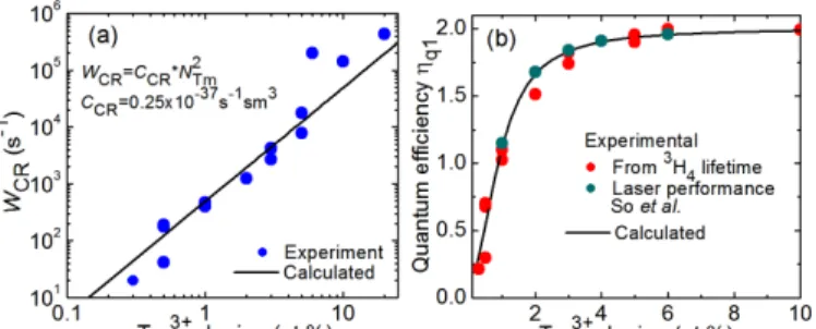
rate was determined using Eqs. (2)-(3) based on the experimental luminescence lifetimes of the 3H4 state, Fig. 3(a).
This figure is plotted in a double-log scale to illustrate the quadratic dependence of WCR on NTm, Eq. (3). The best-fit CCR
= 0.25±0.03×10-37 s-1cm3.
There exist another way to express the CR rate constant [50]: , 1 2 0 Tm 30 CR ⎟⎟ ⎠ ⎞ ⎜⎜ ⎝ ⎛ = C C W
τ
(4)where, CTm is the doping level (in at.%) and C0 is the critical
doping level which corresponds to a 2-fold decrease of the luminescence lifetime of the pump level (3H
4). For Tm:LiYF4,
we calculated C0 as 0.96 at.% (as 1 at.% Tm corresponds to
the ion density of 1.38×10²⁰ at/cm3, crystal density: ρ = 3.95
g/cm3).
The pump quantum efficiency for the 3F
4 state of Tm3+
-doped materials, ηq1, can exceed unity and approach 2 due to
the CR effect (pumping at the 3H6 → 3H4 transition) [14,49].
Assuming no ground-state bleaching and no other processes such as ETU and EM, Honea et al. determined ηq1 (a ratio of
ions excited to the 3F
4 state to the number of absorbed pump
photons) as [50]: . / 1 ) 1 )( / 1 ( 2 / 1 CR 30 32 3rad CR 30 q1 W W + − − + = τ β τ τ η (5)
Here, β32 is the total luminescence branching ratio for the 3H4
→ 3F
the 3H
5 state, both these transitions end up with the ions being
at the 3F
4 state). As explained above, for Tm:LiYF4, τ30 ≈ τ3rad.
The results on ηq1 are shown in Fig. 3(b). For very small Tm3+
doping, ηq1 is limited by the β32 value. For more than 6 at.%
Tm3+ doping, the theoretical pump quantum efficiency exceeding 1.95 (strong CR) is expected. The calculated results agree well with the estimation of So et al. based on analysis of the laser performance [39].
Fig. 3. Quantification of cross-relaxation in Tm:LiYF4: (a) cross-relaxation
rate WCR: symbols – determined from the experimental data on τ3lum(3H4), line
– theoretical calculation using Eq. (3); pump quantum efficiency for the 3F 4
state ηq1: symbols –determined from the experimental WCR rates (this work)
and from the laser performance [39], curve – theoretical calculation using Eq. (5). All data are plotted vs. Tm3+ doping concentration.
In Table II, we compared the parameters defining CR (τ30,
CCR and C0) for several widespread Tm3+-doped laser crystals
[50-52]. Note that CCR for Tm:LiYF4 is by order of magnitude
smaller that in oxide crystals because of much longer intrinsic lifetime of the 3H4 state for this fluoride crystal.
TABLE II
PARAMETERS* OF CROSS-RELAXATION IN TM3+-DOPED CRYSTALS
Crystal τ3rad(3F4), ms τ30(3F4), ms CCR, 10-37 cm6/s Cat.% 0, Ref.
Tm:LiYF4 ~2.2 [46] 2.3 0.25 0.96 This work
Tm:Lu2O3 0.69 0.35 1.25 0.53 [51]
Tm:Y3Al5O12 1.44 0.54 3.95 0.50 [50]
Tm:KLu(WO4)2 >>0.20 0.24 2.7 1.94 [52]
*τ3rad and τ30 – radiative and intrinsic (unquenched) lifetimes of the 3F4 Tm3+
state, respectively; CCR – CR concentration-independent micro-parameter;
C0 – critical Tm3+ doping level.
D. Energy-transfer upconversion
Energy-transfer upconversion in Tm:LiYF4, 3F4 + 3F4 → 3H
4 + 3H6, is a phonon-assisted process which is detrimental
for the ~1.9 µm laser transition [39] but can be useful for the ~2.3 µm one.
To quantify ETU, we excited Tm:LiYF4 crystals directly to
the 3F
4 state (at 1.68 µm) and monitored power dependence of
luminescence from the 3H
4 (at ~1.5 µm) and 3F4 (at ~1.9 µm)
multiplets. The observation of the former emission is a direct evidence of ETU. From the ratio of integrated intensities of these emissions, we deduced the ratio of the populations
N(3H4)/N(3F4), see Fig. 4(a). This ratio was also calculated
numerically using a rate-equation model accounting for the ground-state bleaching, CR, ETU and spatial distribution of the pump, as shown by the curves in Fig. 4(a). From such a modeling, we determined the ETU parameter KETU which
amounted to 3.5±1, 14.5±2 and 22±5×10-20 cm3s-1 for 3, 4 and
5 at.% Tm-doping, respectively. As expected, KETU increases
with the Tm3+ concentration.
A summary of KETU values for Tm:LiYF4 reported to date is
presented in Fig. 4(b). In [48,53], KETU was determined from
luminescence-decay measurements. In [54], we determined it from the modeling of the laser performance and in [55], it was calculated theoretically. For Tm3+ doping below 6 at.% which
is common for laser crystals, the results on KETU are in relative
agreement with each other while for higher doping, a strong discrepancy is observed.
The concentration dependence of KETU has been previously
expressed by a linear law using a concentration-independent micro-parameter CETU [49]:
.
Tm ETU ETUC
N
K
=
(6)In our case, CETU = 3.9±1×10-40 cm6s-1 and it is by two orders
of magnitude smaller than CCR. However, the KETU parameters
of Tm:LiYF4 are high enough to ensure efficient 2.3 µm laser
operation of this crystal, as will be shown below. Note the concentration dependence of KETU seems to be faster than
linear and well fitted with a quadratic curve, Fig. 4(b).
Fig. 4. Quantification of energy-transfer upconverison, 3F
4 + 3F4 → 3H4 + 3H6,
in Tm:LiYF4: (a) ratios of the fractional populations of the 3H4 and 3F4 Tm3+
multiplets for the 1.68 µm excitation (pump spot radius: wP = 120 µm) vs. the
incident pump power for various Tm3+ concentrations: symbols – experimental
data, curves – their rate-equation modeling yielding KETU values; (b) summary
of the ETU parameters reported to date, line and quadratic curve represent their possible concentration-dependences.
III. BULK LASERS AT ~2.3µM
A. Laser set-up
The laser experiments started using bulk Tm:LiYF4 crystal.
The laser crystal was an a-cut 3.5 at.% Tm:LiYF4 having a
cylindrical shape (diameter: 8.5 mm, length: 8.1 mm). The actual Tm3+ ion density NTm = 4.83×1020 cm-3. Both its faces
were polished to laser quality and antireflection (AR) coated for ~1.9 µm. The crystal was mounted on a Cu-holder using a silver thermal paste and it was passively cooled.
The scheme of the laser set-up is shown in Fig. 5. A hemispherical laser cavity was formed by a flat pump mirror (PM) coated for high transmission (HT) at the pump wavelength (T = 81% at 0.79 µm) and at ~1.9 µm (the 3F
4 → 3H
6 Tm3+ emission) and for high reflection (HR) at ~2.3 µm,
and a set of concave output couplers (OCs) with the radius of curvature of 100 mm and a transmission TOC of 0.7%, 1.3%
and 4.0% at 2.3 µm. Due to the R = 95% reflection from the OCs at the pump wavelength, the crystal was pumped in a
double-pass. Moreover, to suppress further the ~1.9 µm emission, all the OCs provided HT (T > 90%) at this wavelength. The geometrical cavity length was about 100 mm. As the first pump source, we used a CW Ti:Sapphire laser (model 3900S, Spectra Physics) delivering 3.2 W at 0.79 µm (M2 ≈ 1). The pump power incident on the crystal was varied
using a rotatory λ/2 plate and a Glan-Taylor polarizer. The pump polarization in the crystal corresponded to π. The pump beam was focused by a spherical lens (focal length: f = 150 mm) resulting in a spot radius wP of 61 µm and a confocal
parameter 2zR of 4.2 cm. The pump beam was mechanically
modulated using a chopper (duty cycle: 1:2, pulse duration: ~10 ms) leading to quasi-CW pumping.
Fig. 5. Scheme of the ~2.3 µm Tm:LiYF4 bulk laser pumped by a Ti:Sapphire
laser: λ/2 – rotatory half-wave plate, P – Glan-Taylor polarizer, L – lens, PM – pump mirror, OC – output coupler, F – cut-off filter.
The second pump source was a fiber-coupled AlGaAs laser diode (DILAS, fiber core diameter: 105 µm, numerical aperture, N.A.: 0.22) emitting up to 28 W of unpolarized output at a wavelength of 793.2 nm (emission bandwidth: <4 nm, M2 ≈ 46). The pump beam was collimated and focused by a pair of spherical lenses (f = 50 mm and 150 mm, respectively) resulting in wP of 150 µm and a Rayleigh length
zR of 5.7 mm. The pump beam was electrically modulated
(duty cycle: 1:20, pulse duration: ~10 ms). Due to the strong divergence of the pump, during the second pump pass (after the reflection from the OC), the diameter of the pump beam in the crystal was ~1.5 mm thus producing minor effect on inversion in the laser crystal. Consequently, the pumping was considered in single-pass.
The radius of the laser mode wL in the crystal was estimated
within the ABCD formalism to be 70 µm (taking into account thermal lens in the crystal).
The laser emission spectra were measured using an optical spectrum analyzer (OSA, model AQ6375B, Yokogawa). The laser output was filtered from the residual pump using a cut-off filter (FEL 900, Thorlabs).
B. Results: Ti:Sapphire pumping
First, we describe the results achieved using the Ti:Sapphire pumping. For all studied OCs, the laser operated solely at the
3H
4 → 3H5 transition with no emission at ~1.9 µm. The laser
output was linearly polarized; the polarization was determined by the gain anisotropy (π), see Fig. 2(a).
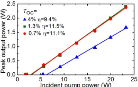
Fig. 6. Ti:Sapphire pumped ~2.3 µm Tm:LiYF4 bulk laser: (a) input-output
dependences, η – slope efficiency; (b) typical laser emission spectra. The laser polarization is π. The pumping is quasi-CW (duty cycle: 1:2).
The maximum peak output power was achieved using 1.3% OC, namely 0.73 W at 2306 nm with a slope efficiency η of 34.6% (vs. the incident pump power Pinc). The input-output
dependence was nonlinear close to the laser threshold (at Pinc
= 0.40 W). Because of this, the fit for the determination of η was performed for pump powers of about 3 times higher than the threshold value, Fig. 6(a). The maximum optical-to-optical efficiency ηopt was 26.7%. For higher TOC = 4%, the laser
operated with slightly higher slope efficiency (35.9%) whilst with lower peak output power of 0.55 W at 2305 nm and much higher laser threshold of 0.81 W. Further power scaling was limited by the available pump power. No thermal roll-over of the input-output dependences or crystal fracture were observed during the laser experiments.
The passive losses in the crystal were estimated to be 0.5% using the Findlay-Clay analysis [56].
The laser emission spectra for all OCs were similar, Fig. 6(b).
We have also studied true CW performance of this laser for the optimum 1.3% OC (i.e., when removing the chopper from the pump beam). The Pinc value was limited to approximately
half of the available power, ~1.5 W. The achieved CW output power was similar to the peak power achieved under quasi-CW regime. The maximum output power reached 0.24 W.
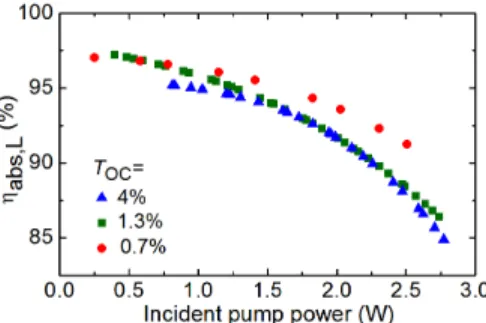
Fig. 7. Pump absorption under lasing conditions ηabs,L for 3.5 at.% Tm:LiYF4
crystal (Ti:Sapphire pumping, wP = 61 µm).
The pump absorption under lasing conditions ηabs,L was
determined by measuring the residual pump power after the OC with a short-pass filter. The results are shown in Fig. 7. The saturation of absorption was observed. In particular for 1.3% OC, ηabs,L decreased from 97.2% to 86.3% when the
pump power increased from the laser threshold to its maximum value, i.e., from 0.40 to 2.74 W. For other OCs, a similar behavior was observed.
According to the measured pump absorption, the slope efficiency vs. the absorbed pump power Pabs for the 1.3% and
4% OCs reached 47.3% and 51.7%, respectively. Here, the fit of the input-output dependence was performed starting from the pump power well above the laser threshold as explained above. Thus, this work represents the best results in terms of output power and slope efficiency for any laser-pumped 2.3 µm laser, cf. Table I.
C. Results: diode-pumping
The results for diode-pumping are shown in Fig. 8. For all OCs, the laser generated a linearly polarized emission (π) at ~2306 nm. The input-output dependences were linear. For 1.3% OC, the laser generated a maximum peak output power of 2.4 W (average power: 0.12 W) with η = 11.5%. The laser threshold was at Pinc = 2.0 W and ηopt amounted to 10.3%. For
higher output coupling, the laser performance deteriorated. The input-output dependences were linear up to at least Pinc =
23.2 W.
The pump absorption ηabs,L was weakly dependent on the
OC and the pump power and amounted to 60%. Thus, the maximum slope efficiency vs. the absorbed pump power was 19.2% (for TOC = 1.3%) which is much lower than in the case
of Ti:Sapphire pumping.
Fig. 8. Input-output dependences of diode-pumped ~2.3 µm Tm:LiYF4 bulk
laser, η – slope efficiency. The laser polarization is π. The pumping is quasi-CW (duty cycle: 1:20).
D. Modeling of the laser performance
For modeling of the laser performance, we will consider the results achieved under Ti:Sapphire pumping. The model will account for ground-state bleaching, CR and ETU. The system of rate equations for Tm3+ ions is as following:
, 2 2 L2 L2 3 SE 2 2 2 2 ETU 3 1 CR 2 K NN K N N I N dt dN
σ
τ
+ − − = (7a) , 3 L2 L2 SE 30 3 2 2 ETU 3 1 CR 1 P P abs 3 I N K NN K N N I N dt dNσ
τ
σ
− + − − = (7b)where, Ni (i = 1, 2, 3) is the ion density for the i-th level,
Fig. 1(b), N1 + N2 + N3 = NTm, t is time, KCR = WCR/NTm is the
CR macroscopic parameter expressed in cm3s-1, τ2 is the
lifetime of the 2nd level (3F4), τ30 is the intrinsic (unquenched)
lifetime of the 3rd level (3H4), σL2SE is the SE cross-section at
the laser frequency νL2 (3H4 → 3H5) σPabs is the absorption
cross-section at the pump frequency νP, IP and IL2 are the pump
and laser intensities expressed in photons/(s·cm²). We will neglect the radiative decay in the 3 → 2 channel because the
corresponding luminescence branching ratio β32 is small [38].
In Eq. (7), we assume no lasing at the 3F
4 → 3H6 transition
with a frequency νL1 (so that IL1 ≡ 0).
In the first approach, we will derive the pump quantum efficiency for the 3H4 → 3H5 transition ηq2 from the measured
output power of the laser Pout. According to the definition of
ηq2 (the ratio of the number of emitted photons at ~2.3 µm to
the number of absorbed pump photons), from the formalism of the rate equations, we have:
. 1 P P abs 3 L2 L2 SE 30 3 q2 I N N I N
σ
σ
τ
η
+ = (8)The population of the upper laser level N3 can be estimated
from the threshold condition (gain is equal to losses):
. 2 OC 3 L2 SE L T N ℓ= +
σ
(9)Here, ℓ is the thickness of the crystal and L are the passive losses. In this equation, we neglect the axial dependence of the population N3. By deriving N3 from Eq. (9) and substituting it
into Eq. (8), we determined IL2 and, then, the output laser
intensity Iout = TOC·(IL2/2). The output power Pout is then given
by: , out 2 L L2 out h w I P =
ν
π
(10a) . 2 L2 30 SE 2 L L2 OC inc abs q2 OC OC 2 P 2 L P L2 outτ
σ
π
ν
η
η
ν
ν
T h w P L T T w w h h P − + = (10b)Here, wL is the radius of the laser mode in the crystal and we
have also taken into account that the pump absorption ηabs =
σPabsN1ℓ and the incident pump power Pinc = hνPπwP2IP. The
first term of Eq. (10b) represents an expression for the laser slope efficiency vs. the absorbed pump power Pabs = ηabs·Pinc
containing four factors: the Stokes efficiency ηSt = hνL2/hνP,
the mode overlap efficiency ηmode = wL2/wP2 (we assume ηmode
≈ 1), the output-coupling efficiency ηOC = TOC/(TOC+L) and the
pump quantum efficiency ηq2. From Eq. (10b), the laser
threshold is: . 2 L2 30 q2 abs SE OC 2 P P th
η
η
τ
σ
π
ν
w T L h P = + (11)Using Eq. (10b), we were able to determine ηq2 for each point
at the input-output laser dependence from Fig. 6(a).
The calculated ηq2 values are shown in Fig. 9. For all
studied OCs, the quantum efficiency gradually increases with the incident pump power. The variation is from 0.14 to 1.27 for the optimum 1.3% OC. The values of ηq2 exceeding unity
represent a direct evidence of the effect of ETU on the laser performance. Indeed, ETU is responsible for re-feeding the upper laser level (3H
4) at the expense of the 3F4 population.
threshold clearly represents the effect of CR which is a detrimental process decreasing the upper laser level population.
Fig. 9. Pump quantum efficiency for the 3H
4 → 3H5 laser channel (pumping to
the 3H
4 state) ηq2 calculated using Eq. (10b).
To reveal the effect of CR and ETU on the pump quantum efficiency, we have derived another expression for ηq2 based
on the populations of the Tm3+ multiplets. In the steady-state
conditions (dNi/dt = 0), by combining Eq. (8) and Eq. (7b), we
obtained: . 1 1 P P abs 2 2 ETU 1 P P abs 3 1 CR q2 I N N K N I N N K
σ
σ
η
= − + (12)This equation shows that that there exist two competitive energy-transfer processes which determine ηq2, namely CR
and ETU. If both processes are negligible (an ideal case of almost zero doping concentration), ηq2 ≡ 1 and the laser slope
efficiency will be limited by the Stokes efficiency. If there is no ETU, the quantum efficiency will be less than unity due to CR. Finally, if there are two processes (CR and ETU), ηq2 may
exceed unity as observed in Fig. 9.
There exist upper limit for ηq2. By combining Eq. (12), the
rate-equation, Eq. 7(a), at the steady-state (dN2/dt = 0), and the
intuitive expression for ηq2, Eq. (8), we obtain:
. 1 2 2 2 30 3 1 P P abs q2 ⎟⎟ ⎠ ⎞ ⎜⎜ ⎝ ⎛ + − =
τ
τ
σ
η
N N N I (13)From this equation, ηq2 ≤ 2. The upper limit can be reached for
a material exhibiting strong ETU and long lifetimes of the 3H 4
and 3F
4 multiplets and pumped well above the laser threshold
when the laser operates solely at the 3H
4 → 3H5 transition, so
that the 3H4 level is depopulated by ~2.3 µm laser emission
and the 3F4 one is depopulated by ETU.
From these considerations, it is possible to explain the decrease of pump absorption ηabs (bleaching) with the pump
power, Fig. 7. This is because when there is no laser operation at the 3F
4 → 3H6 transition, the population of the ground-state 3H
6 is not clamped by the threshold condition. Thus, with an
increased pump power, the ground-state is depopulated while the Tm3+ ions are accumulated in the metastable intermediate 3F
4 state. Note that when the laser operates at both the 3H4 → 3H
5 and 3F4 → 3H6 transitions simultaneously, ηabs is expected
to be nearly constant with the pump power.
Within the second approach, we solved the system of rate equations, Eq. (7), numerically accounting for the spatial and axial distribution of the pump and laser fields in the crystal. Then, the laser output power at ~2.3 µm was determined from Eq. (10a) and ηq2 was determined from Eq. (12).
First, we performed the calculations assuming that the laser operates solely at the 3H
4 → 3H5 transition (IL1 ≡ 0). Three
different Tm3+ doping levels of 1.5, 3.5 and 6.5 at.% were
considered. The CR and ETU parameters were as following:
KCR = 0.52, 1.21 and 2.24×10⁻¹⁷ cm3s-1 and KETU = 0.3, 1.4 and
4.5×10⁻¹⁹ cm3s-1, respectively. The calculations were done
under two assumptions: (i) there exist both CR and ETU processes (KCR ≠ 0, KETU ≠ 0); (ii) there exist only CR while
ETU is absent (KCR ≠ 0, KETU = 0). The spectroscopic
parameters of Tm3+ ions were as following: σL2SE = 0.57×10⁻²⁰
cm2, σP
abs = 0.63×10⁻²⁰ cm2 at 791 nm (for π-polarization) [46],
τ30 = 2.3 ms, τ2 = 10 ms [46]. The incident pump power was
fixed (Pinc = 3.0 W).
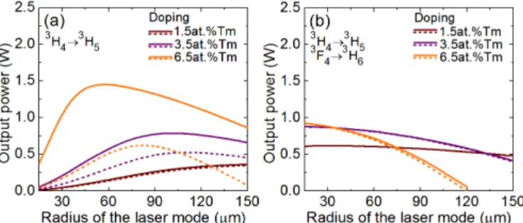
The results on the output power at ~2.3 µm are presented in Fig. 10(a). When there is no ETU in the system (KCR ≠ 0, KETU
= 0), for a fixed (small) radius of the laser mode (e.g., wL = 60
µm as in our case), the output power slightly increases with the Tm3+ doping due to the increased pump absorption. When
the ETU is present (KCR ≠ 0, KETU ≠ 0), the output power is
greatly increased and this effect becomes more evident for higher Tm3+ doping levels because the action of ETU against
CR is enhanced. Moreover, for each Tm3+ concentration, there
is an optimum radius of the laser mode maximizing the output power. With an increase of the Tm3+ doping, the optimum wL
value decreases. For 3.5 at.% Tm-doping, the laser geometry used in the present work, cf. Fig. 5, provided almost optimum
wL value.
Fig. 10. Calculated output power at ~2.3 µm of a diode-pumped Tm:LiYF4
laser with different doping levels, solid curves – KCR ≠ 0, KETU ≠ 0, dashed
ones - KCR ≠ 0, KETU = 0: (a) the laser operating at the 3H4 → 3H5 transition
only; (b) the laser operating at both the 3H
4 → 3H5 and 3F4 → 3H6 transitions
simultaneously. The Tm3+ doping is 1.5, 3.5 and 6.5 at.%, P
inc = 3.0 W, TOC =
2.0%, L = 0.2%, ℓ = 9.0 mm.
Furthermore, we have analyzed the laser performance for operation at both the 3H4 → 3H5 and 3F4 → 3H6 transitions
simultaneously. For this, the term –σL1SEIL1N2 representing
stimulated-emission at νL1 (at ~1.9 µm) was added to the
rate-equation, Eq. (7a). The results are shown in Fig. 10(b). In this case, the effect of ETU on the laser performance is minor because population of the 3F
4 state is clamped by the threshold
condition for the 3F
4 → 3H6 laser. For a fixed (small) wL, the
the increased pump absorption and finally saturates.
To conclude, the simultaneous operation of the Tm lasers at both the 3H4 → 3H5 and 3F4 → 3H6 transitions is mostly
detrimental for their ~2.3 µm laser performance, especially at high doping levels. Moreover, in the case of single laser operation (3H
4 → 3H5) the efficiency of the ~2.3 µm laser can
be greatly enhanced by using highly Tm3+-doped crystals due
to the ETU effect.
The existence of the optimum size of the laser mode for the ~2.3 µm Tm:LiYF4 laser operating solely at the 3H4 → 3H5
transition is due to (i) strong dependence of pump absorption
ηabs or, equivalently, ground-state bleaching, on the pump spot
radius wP (notice that in this modeling, we assumed wL ≈ wP),
see Fig. 11(a), and (ii) increase of the laser threshold with increasing pump spot size. Physically, the first effect is explained as following: if there is no laser operation at the 3F
4
→ 3H
6 transition, the population of the ground-state (3H6) is
not clamped by the threshold condition and thus it can be depopulated for high pump intensities (for small wP). ETU
increases the pump absorption because it brings excited Tm3+ ions back to the ground-state. Thus, the optimum size of the laser mode decreases with Tm3+ doping due to enhanced ETU.
When the laser operates at both the 3H
4 → 3H5 and 3F4 → 3H
6 transitions simultaneously, the size of the pump mode and
ETU have minor action on the pump absorption, Fig. 11(b).
Fig. 11. Calculated pump absorption ηabs for a diode-pumped Tm:LiYF4 laser
with different doping levels, solid curves – KCR ≠ 0, KETU ≠ 0, dashed ones -
KCR ≠ 0, KETU = 0: (a) the laser operating at the 3H4 → 3H5 transition only; (b)
the laser operating at both the 3H
4 → 3H5 and 3F4 → 3H6 transitions
simultaneously. The parameters used for modeling are listed in the text.
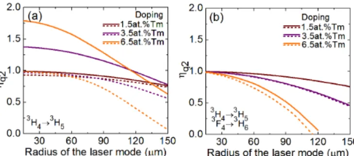
In Fig. 12, the calculated pump quantum efficiency ηq2 for
the Tm:LiYF4 laser is shown. When the laser operates solely
at the 3H
4 → 3H5 transition and there is no ETU in the system
(KCR ≠ 0, KETU = 0), the ηq2 value has an upper limit of 1 and it
has almost no dependence on the Tm3+ doping level for small radii of the pump mode. If the ETU is present (KCR ≠ 0, KETU ≠
0), the pump quantum efficiency greatly increases with Tm3+ doping approaching the upper limit of 2, Fig. 12(a). Note that for about 1–2 at.% Tm-doping which was typically used in the previous studies [17,19,20,25], ηq2 is below 1 which agrees
with the observed laser slope efficiencies. For 3.5 at.% Tm-doping, as in our case, ηq2 > 1 can be observed, cf. Fig. 9.
Fig. 12. Calculated pump quantum efficiency ηq2 for for a diode-pumped
Tm:LiYF4 laser with different doping levels, solid curves – KCR ≠ 0, KETU ≠ 0,
dashed ones - KCR ≠ 0, KETU = 0: (a) the laser operating at the 3H4 → 3H5
transition only; (b) the laser operating at both the 3H
4 → 3H5 and 3F4 → 3H6
transitions simultaneously. The parameters used for modeling are listed in the text.
When the laser operates at both the 3H4 → 3H5 and 3F4 → 3H
6 transitions simultaneously, ηq2 cannot exceed unity even
under the conditions of high Tm3+ doping and, consequently,
strong ETU, Fig. 12(b).
Using the above described second approach, we calculated the values of the maximum output power Pout, threshold power
Pth, slope efficiency η (vs. the incident pump power) and the
maximum pump quantum efficiency ηq2(max) for the studied 3.5
at.% Tm:LiYF4 laser, see Table III. The results of calculation
are in reasonable agreement with the experimental data. This confirms the first observation of more than unity pump quantum efficiency ηq2 for the ~2.3 µm laser transition in bulk
Tm:LiYF4.
TABLE III
LASER PERFORMANCE* OF ~2.3µM BULK TM:LIYF4LASERS
TOC Data Pout, W Pth, W η, % ηq2(max)
0.7% Exp. 0.49 0.24 30.3 1.08 Calc. 0.52 0.24 20.8 1.30 1.3% Exp. 0.73 0.40 34.6 1.27 Calc. 0.65 0.36 27.2 1.23 4% Exp. 0.55 0.81 35.9 0.85 Calc. 0.63 0.99 36.3 0.93
*Pout – output power, Pth – threshold incident power, η – slope efficiency
vs. the incident pump power, ηq2(max) – pump quantum efficiency at the
maximum pump power.
IV. WAVEGUIDE LASERS AT ~2.3µM
A. Fabrication of waveguides
Single-crystalline 6.2 at.% Tm, 3.5 at.% Gd:LiYF4 thin film
was grown on undoped (001)-oriented LiYF4 substrate by the
Liquid Phase Epitaxy (LPE) method [54]. The actual Tm3+ ion
density NTm = 8.56×1020 cm-3. The optically passive Gd3+ ions
were added to enhance the refractive index contrast between the active layer and the substrate (Δn = 2.3±0.5×10⁻³). The film thickness was 30 µm.
The films were further microstructured by diamond saw dicing resulting in surface channel (ridge) waveguides (WGs) oriented along the a-axis and having a square cross-section of 30×30 µm2. The length of the WGs was 8.0 mm. The WG
propagation losses were 0.28±0.1 dB/cm at ~1.9 µm. More details can be found in [54].
B. Laser set-up
The scheme of the waveguide laser is shown in Fig. 11. The sample with the WG was mounted on a Cu-holder using a silver thermal paste. It was passively cooled. The laser cavity was composed of a flat PM coated for HR at 1.88-2.32 µm and HT at the pump wavelength (T = 69% at 0.79 µm), and a set of two flat OCs coated for HT at 1.83-1.88 µm (T = 90% / 97%) and having a transmission of 4% / 1.3% at 2.3 µm, respectively. Both PM and OC were placed as close as possible to the WG end-facets. No index-matching liquid was used to avoid damage of the optical elements.
As a pump source, we used the same Ti:Sapphire laser, see Section IIIA. The pump polarization corresponded to π in the WG. The pump beam was focused by an uncoated CaF2
spherical lens (f = 40 mm, T = 93.8% at 0.79 µm) providing a pump spot diameter at the input face of the WG 2wP of ~30
µm. The pump coupling efficiency ηcoupl was determined from
pump-transmission measurements at 0.84 µm (out of Tm3+ absorption) to be 87±1%. The pump absorption at the laser threshold ηabs(1-pass) was measured to be 71.0±0.5%. Both OCs
provided partial reflection at the pump wavelength (R = 93% / 96%, respectively) and thus the WG was pumped in a double-pass. The calculated total pump absorption ηabs(2-pass) amounted
to 90.1%. The pump beam was mechanically modulated using a mechanical chopper (1:2 duty cycle, 10 ms pump pulses).
The WG laser operated at the fundamental transverse mode. The mode radius wL was 15 µm.
Fig. 13. Scheme of the ~2.3 µm Tm:LiYF4 channel WG laser: λ/2 – rotatory
half-wave plate, P – Glan-Taylor polarizer, L – lens, PM – pump mirror, OC – output coupler, F –cut-off / bandpass filter.
The output laser beam was collimated using a spherical lens (f = 50 mm). The total output power was determined after filtering the residual pump using a cut-off filter (FEL 900, Thorlabs). The power at ~2.3 µm was separately determined using a bandpass filter (FB2250-500, Thorlabs).
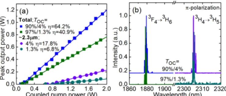
C. Laser performance
The WG Tm:LiYF4 laser operated at both ~1.9 µm and ~2.3
µm transitions for both OCs. The laser output was linearly polarized (π).
The best results were achieved using the output coupler having a transmission of 90% / 4% at ~1.9 µm / 2.3 µm. The maximum peak total output power reached 1.13 W with a total slope efficiency ηΣ of 64.2% (vs. the coupled pump power). The laser threshold was at 0.10 W and the total optical-to-optical efficiency ηΣopt amounted to 59.4%. Near the threshold,
the laser operated solely at the 3F
4 → 3H6 transition. For the
pump power exceeding 0.68 W, the emission due to the 3H 4 →
3H
5 transition appeared, as shown in Fig. 11(a). The
corresponding peak output power reached 0.23 W with η = 17.8%. According to the pump absorption efficiency ηabs(2-pass),
the slope efficiency vs. the absorbed pump power was 19.8% being smaller than in the bulk laser. For the second studied OC, the laser performance was inferior.
The typical spectra of the laser emission are shown in Fig. 11(b). The emission corresponding to the 3F
4 → 3H6
transition occurred at 1877-1881 nm in agreement with the gain spectra for π-polarization. The 3H
4 → 3H5 laser transition
operated at 2304-2307 nm (both for TOC = 90% / 4%). The
multi-peak spectral behavior for both transitions is due to the etalon effects at the WG / mirror interfaces.
The achieved results represent the first ~2.3 µm thulium
waveguide laser.
Fig. 14. Ti:Sapphire pumped ~1.9 µm & 2.3 µm Tm:LiYF4 waveguide laser:
(a) input-output dependences, η – slope efficiency; (b) typical laser emission spectra. The laser polarization is π. The pumping is quasi-CW (duty cycle: 1:2).
D. Modeling of laser performance
The performance of the WG laser was modeled numerically using the second approach described above. The results of this modeling are summarized in Table IV. Here, PΣout is the total
output power (for both the 3H
4 → 3H5 and 3F4 → 3H6 laser
transitions), PΣ
th is the corresponding laser threshold and ηΣ is
the corresponding slope efficiency (both vs. the coupled pump power). The values without the “Σ” superscript refer solely to the ~2.3 µm emission. For the WG laser, it was not possible to derive the ηq2 value from the output power (using the first
approach) because of simultaneous operation of the laser at ~1.9 µm and ~2.3 µm.
TABLE IV
LASER PERFORMANCE* OF ~2.3µM WAVEGUIDE TM:LIYF4LASERS
TOC Data PΣout, W PΣ th, W ηΣ, % Pout, W Pth, W η, % ηq2(max) 90% / 4% Exp. 1.13 0.10 64.2 0.23 0.68 17.8 – Calc. 0.99 <0.1 37.4 0.23 <0.2 12.0 0.91 97% / 1.3% Exp. 0.71 0.11 40.9 0.09 0.64 6.8 – Calc. 0.84 <0.1 37.1 0.10 <0.2 5.1 0.93
*Pout –output power, Pth – threshold incident power, η – slope efficiency vs.
the incident pump power (the values with “Σ”: emission at both the 3H 4 → 3H5
and 3F
4 → 3H6 transitions, without “Σ”: emission at the 3H4 → 3H5 transition,
ηq2(max) – pump quantum efficiency at the maximum pump power.
The model reasonably explains the observed output power at ~2.3 µm while it predicts lower values for the laser threshold. The maximum ηq2 values are still below 1 in
the 3H
4 → 3H5 and 3F4 → 3H6 transitions, Fig. 12(b).
V. CONCLUSIONS
To conclude, the laser operation at the 3H4 → 3H5 Tm3+
transition is a promising route towards efficient mid-IR bulk and waveguide oscillators operating around ~2.3 µm. Under the condition that the competitive 3F
4 → 3H6 laser channel is
suppressed, a pump quantum efficiency of more than unity (potentially, up to 2) can be achieved thus leading to a laser slope efficiency well exceeding the Stokes limit. This is due to the energy-transfer upconversion acting against cross-relaxation and populating the upper laser level. Strong ETU is linked to the use of moderate and high Tm3+ doping levels that simultaneously bring high pump absorption efficiency and, in part, to the adjusted pump mode size.
Fluoride LiYF4 crystals with moderate Tm3+ doping levels
of few at.% appear as excellent candidates for highly-efficient ~2.3 µm lasers because of a combination of easy Tm3+ doping,
low phonon energies and good thermo-mechanical properties of the host crystal and suitable spectroscopic behavior of the dopant Tm3+ ions. In the present work, we report on a compact bulk 3.5 at.% Tm:LiYF4 laser generating a maximum output
power of 0.72 W (quasi-CW operation) at 2306 µm with a record-high slope efficiency of 47.3% versus the absorbed pump power (thus overcoming the Stokes efficiency, 34.4%). We show the first experimental evidence of more than unity pump quantum efficiency in this laser. By applying diode pumping, the power scaling strategy is demonstrated with a clear potential for improvement.
We also report on the first ~2.3 µm Tm waveguide laser based on epitaxially-grown 6.2 at.% Tm:LiYF4 layers. Due to
the simultaneous operation of the waveguide laser at both the
3H
4 → 3H5 and 3F4 → 3H6 transitions, the pump quantum
efficiency was upper-limited to be less than unity despite the high Tm3+ doping level. The laser generated 0.23 W at
2304-2307 nm with a slope efficiency of 19.8% versus the absorbed pump power. Further efforts on ~2.3 µm Tm waveguide lasers should be focused on suppression of laser operation at the high-gain 3F4 → 3H6 transition, e.g., by dielectric coatings.
Our conclusions about the mechanism of ~2.3 µm laser operation are valid for other Tm3+-doped fluoride crystals, such as CaF2, LiLuF4, BaY2F8, or even other oxide hosts. A
comparative study of CR and ETU parameters of these materials is required to select the best fluoride gain material for the laser operation at the 3H
4 → 3H5 transition.
REFERENCES
[1] F. J. McAleavey, J. O'Gorman, J. F. Donegan, B. D. MacCraith, J. Hegarty, and G. Mazé, “Narrow linewidth, tunable Tm3+-doped fluoride
fiber laser for optical-based hydrocarbon gas sensing,” IEEE J. Sel. Top.
Quantum Electron., vol. 3, No. 4, pp. 1103–1111, Aug. 1997.
[2] M. E. Webber, J. Wang, S. T. Sanders, D. S. Baer, and R. K. Hanson, “In situ combustion measurements of CO, CO2, H2O and temperature
using diode laser absorption sensors,” Proc. Combust. Inst., vol. 28, no. 1, pp. 407–413, 2000.
[3] F. J. McAleavey, J. O'Gorman, J. F. Donegan, J. Hegarty, and G. Maze, "Extremely high sensitivity gas detection at 2.3 µm using a grazing incidence Tm3+ fibre laser cavity," Sens. Actuator A – Phys., vol. 87, no.
3, pp. 107–112, Jan. 2001.
[4] J. Cihelka, I. Matulková, and S. Civiš, "Laser diode photoacoustic and FTIR laser spectroscopy of formaldehyde in the 2.3 µm and 3.5 µm spectral range," J. Molec. Spectr., vol. 256, no. 1, pp. 68–74, July 2009. [5] A. Garnache, A. Liu, L. Cerutti, and A. Campargue, “Intracavity laser
absorption spectroscopy with a vertical external cavity surface emitting laser at 2.3 µm: Application to water and carbon dioxide,” Chem. Phys.
Lett., vol. 416, no. 1-3, pp. 22–27, Nov. 2005.
[6] S.T.Fard, W. Hofmann, P. T. Fard, G. Bohm, M. Ortsiefer, E. Kwok, M. C. Amann, and L. Chrostowski, “Optical absorption glucose measurements using 2.3 µm vertical-cavity semiconductor lasers,” IEEE
Photon. Technol. Lett., vol. 20, no. 11, pp. 930-932, June 2008.
[7] I. T. Sorokina, E. Sorokin, S. Mirov, V. Fedorov, V. Badikov, V. Panyutin, and K. I. Schaffers, "Broadly tunable compact continuous-wave Cr2+:ZnS laser," Opt. Lett., vol. 27, no. 12, pp. 1040-1042, June
2002.
[8] G. J. Wagner, T. J. Carrig, R. H. Page, K. I. Schaffers, J.-O. Ndap, X. Ma, and A. Burger, "Continuous-wave broadly tunable Cr2+:ZnSe laser,"
Opt. Lett., vol. 24, no. 1, pp. 19-21, Jan. 1999.
[9] L. Cerutti, A. Garnache, A. Ouvrard, M. Garcia, and F. Genty, “Vertical cavity surface emitting laser sources for gas detection,” Phys. Status
Solidi A, vol. 202, no. 4, pp. 631-635, Feb. 2005.
[10] E. Geerlings, M. Rattunde, J. Schmitz, G. Kaufel, H. Zappe, and J. Wagner, “Widely tunable GaSb-based external cavity diode laser emitting around 2.3 µm,” IEEE Photon. Technol. Lett, vol. 18, no. 18, pp. 1913-1915, Sept. 2006.
[11] R. Wang, S. Sprengel, A. Malik, A. Vasiliev, G. Boehm, R. Baets, M. C. Amann, and G. Roelkens, “Heterogeneously integrated III–V-on-silicon 2.3µm distributed feedback lasers based on a type-II active region,”
Appl. Phys. Lett, vol. 109, no. 22, pp. 221111, Nov. 2016.
[12] G. Boehm, A. Bachmann, J. Rosskopf, M. Ortsiefer, J. Chen, A. Hangauer, R. Meyer, R. Strzoda, and M.C. Amann, “Comparison of InP-and GaSb-based VCSELs emitting at 2.3 µm suitable for carbon monoxide detection,” J. Cryst. Growth, vol. 323, no. 1, pp. 442-445, May 2011.
[13] R. C. Stoneman, and L. Esterowitz, "Efficient, broadly tunable, laser-pumped Tm:YAG and Tm:YSGG cw lasers," Opt. Lett., vol. 15, no. 9, pp. 486-488, May 1990.
[14] K. van Dalfsen, S. Aravazhi, C. Grivas, S. M. García-Blanco, and M. Pollnau, "Thulium channel waveguide laser with 1.6 W of output power and ~80% slope efficiency," Opt. Lett., vol. 39, no. 15, pp. 4380-4383, Aug. 2014.
[15] H. P. Jenssen, A. Linz, R. P. Leavitt, C. A. Morrison, and D. E. Wortman, “Analysis of the optical spectrum of Tm3+ in LiYF
4,” Phys.
Rev. B, vol. 11, no. 1, pp. 92-101, Jan. 1975.
[16] J. Caird, L. DeShazer, and J. Nella, “Characteristics of room-temperature 2.3-µm laser emission from Tm3+ in YAG and YAlO
3,”
IEEE J. Quantum Electron., vol. 11, no. 11, pp. 874-881, Nov. 1975.
[17] J. F. Pinto, L. Esterowitz, and G. H. Rosenblatt , “Tm3+:YLF laser
continuously tunable between 2.20 and 2.46 µm,” Opt. Lett., vol. 19, no. 12, pp. 883-885, June 1994.
[18] D. Bar-Joseph, “2.32-micron flash-lamp-pumped high-repetition-rate laser operation in Tm:Cr:YAG,” Proc. SPIE, vol. 1627, pp. 81-85, June 1992.
[19] V. Sudesh, and J.A. Piper, “Spectroscopy, modeling, and laser operation of thulium-doped crystals at 2.3 µm,” IEEE J. Quantum Electron., vol. 36, no. 7, pp. 879-884, July 2000.
[20] F. Canbaz, I. Yorulmaz, and A. Sennaroglu, “2.3-µm Tm3+:YLF laser
passively Q-switched with a Cr2+:ZnSe saturable absorber,” Opt. Lett.,
vol. 42, no. 9, pp. 1656-1659, May 2017.
[21] A. Braud, S. Girard, J. L. Doualan, M. Thuau, R. Moncorgé, and A. M. Tkachuk, “Energy-transfer processes in Yb:Tm-doped KY3F10, LiYF4,
and BaY2F8 single crystals for laser operation at 1.5 and 2.3 µm,” Phys.
Rev. B, vol. 61, no. 8, pp. 5280-5292, Feb.2000.
[22] A. Diening, P.A. Möbert, and G. Huber, “Diode-pumped continuous-wave, quasi-continuous-continuous-wave, and Q-switched laser operation of Yb3+,
Tm3+:YLiF
4 at 1.5 and 2.3 µm,” J. Appl. Phys., vo. 84, no. 11, pp.
5900-5904, Nov. 1998.
[23] P. S. F. De Matos, N. U. Wetter, L. Gomes, I. M. Ranieri, and S. L. Baldochi, “A high power 2.3 µm Yb:Tm:YLF laser diode-pumped simultaneously at 685 and 960 nm,” J. Opt. A, vol.10, no. 10, pp. 104009-1-7, Aug. 2008.
[24] G. J. Kintz, L. Esterowitz, and R. Allen, “Cascade laser emission at 2.31 and 2.08 µm from laser diode pumped Tm,Ho:LiYF4 at room
Williamsburg, Virginia United States: OSA Technical Digest, 1987, vol.
paper MC2.
[25] I. Yorulmaz, and A. Sennaroglu, “Low-threshold diode-pumped 2.3-µm Tm3+: YLF lasers,” IEEE J. Sel. Top. Quantum Electron., vol. 24, no. 5,
pp. 1601007-1-7, Sept-Oct. 2018.
[26] F. Canbaz, I. Yorulmaz, and A. Sennaroglu, “Kerr-lens mode-locked 2.3-µm Tm3+:YLF laser as a source of femtosecond pulses in the
mid-infrared,” Opt. Lett., vol. 42, no.19, pp. 3964-3967, Oct. 2017. [27] R. Soulard, A. Tyazhev, J.L. Doualan, A. Braud, A. Hideur, M. Laroche,
B. Xu, and P. Camy, “2.3 µm Tm3+:YLF mode-locked laser,” Opt. Lett.,
vol. 42, no. 18, pp. 3534-3536, Sept. 2017.
[28] R. Allen, and L. Esterowitz, “CW diode pumped 2.3 µm fiber laser,”
Appl. Phys. Lett., vol. 55, no. 8, pp. 721-722, June 1989.
[29] J. N. Carter, D. C. Hanna, R. G. Smart, and A. C. Tropper, “Thulium-doped fluorozirconate fiber lasers operating at around 0.8, 1.47, 1.9, and 2.3 µm pumped at 0.79 µm,” in Advanced Solid State Lasers, 18 March
1991, Hilton Head, South Carolina, United States: OSA Proceedings
Series, 1991, vol. 10, paper. MIL13.
[30] R.M. El-Agmy, and N.M. Al-Hosiny, “2.31 µm laser under up-conversion pumping at 1.064 µm in Tm3+: ZBLAN fibre lasers,”
Electron. Lett., vol. 46, no. 13, pp. 936-937, June 2010.
[31] S. V. Muravyev, E. A. Anashkina, A. V. Andrianov, V. V. Dorofeev, S. E. Motorin, M. Y. Koptev, and A. V. Kim, “Dual-band Tm3+-doped
tellurite fiber amplifier and laser at 1.9 µm and 2.3 µm,” Sci. Rep., vol. 8, no. 1, pp. 16164, Nov. 2018.
[32] C. Jia, B.J. Shastri, P.R. Prucnal, M. Saad, and L. R. Chen,
“Simultaneous Q-switching of a Tm3+:ZBLAN fiber laser at 1.9 µm and
2.3 µm using graphene,” IEEE Photon. Technol. Lett., vol. 29, no. 4, pp. 405-408, Jan. 2017.
[33] M. Schellhorn, “High-power diode-pumped Tm:YLF laser,” Appl. Phys.
B, vol. 91, no. 1, pp. 71–74, Apr. 2008.
[34] P. Loiko, J. M. Serres, X. Mateos, S. Tacchini, M. Tonelli, S. Veronesi, D. Parisi, A. Di Lieto, K. Yumashev, U. Griebner, and V. Petrov, "Comparative spectroscopic and thermo-optic study of Tm:LiLnF4 (Ln =
Y, Gd, and Lu) crystals for highly-efficient microchip lasers at ~2 µm,"
Opt. Mater. Express, vol. 7, no. 3, pp. 844-854, Mar. 2017.
[35] S. A. Miller, H. E. Rast, and H. H. Caspers, “Lattice vibrations of LiYF4,” J. Chem. Phys., vol. 52, no. 8, pp. 4172-4175, Apr. 1970. [36] R. L. Aggarwal, D. J. Ripin, J. R. Ochoa, and T. Y. Fan, “Measurement
of thermo-optic properties of Y3Al5O12, Lu3Al5O12, YAlO3, LiYF4,
LiLuF4, BaY2F8, KGd(WO4)2, and KY(WO4)2 laser crystals in the 80–
300 K temperature range,” J. Appl. Phys., vol. 98, no. 10, pp. 103514-1-14, Nov. 2005.
[37] B. Cockayne, J. G. Plant, and R. A. Clay, “The Czochralski growth and laser characteristics of Li(Y,Er,Tm,Ho)F4 and Li(Lu,Er,Tm,Ho)F4
scheelite single crystals,” J. Cryst. Growth, Vol. 54, No. 3, pp.407-413, Sept. 1981.
[38] B. M. Walsh, N. P. Barnes, and B. Di Bartolo, “Branching ratios, cross sections, and radiative lifetimes of rare earth ions in solids: Application to Tm3+ and Ho3+ ions in LiYF
4,” J. Appl. Phys., vol. 3, no. 5, pp.
2772-2787, Mar. 1998.
[39] S. So, J. I. Mackenzie, D. P. Sheperd, W. A. Clarkson, J. G. Betterton, and E. K. Gorton, “A power-scaling strategy for longitudinally diode-pumped Tm:YLF lasers,” Appl. Phys. B, vol. 84, no. 3, pp. 389–393, Sept. 2006.
[40] B. Aull, and H. Jenssen, “Vibronic interactions in Nd:YAG resulting in nonreciprocity of absorption and stimulated emission cross sections,”
IEEE J. Quantum Electron., vol. 18, no. 5, pp. 925-930, May 1982.
[41] N. P. Barnes and D. J. Gettemy, “Temperature variation of the refractive indices of yttrium lithium fluoride,” J. Opt. Soc. Am., vol. 70, no. 10, pp. 1244-1247, Oct. 1980.
[42] C. Görller-Walrand, and K. Binnemans, “Spectral intensities of f-f transitions,” Handbook on the physics and chemistry of rare earths, vol. 25, pp.101-264, 1998.
[43] I. Razumova, A. Tkachuk, A. Nikitichev, and D. Mironov, “Spectral-luminescent properties of Tm:YLF crystal,” J. Alloy Compd., vol. 225, no. 1-2, pp. 129-132, July 1995.
[44] G. Armagan, A. M. Buoncristiani, A. T. Inge, and B. Di Bartolo, "Comparison of spectroscopic properties of Tm and Ho in YAG and YLF crystals,” in Advanced Solid State Lasers, 18 March 1991, Hilton
Head, South Carolina, United States: OSA Proceedings Series, 1991,
vol. 10, paper. MIL14.
[45] A. M. Tkachuk, I. K. Razumova, E. Y. Perlin, M. F. Joubert, and R. Moncorge, “Luminescence self-quenching in Tm3+:YLF crystals: II. The
luminescence decay and macrorates of energy transfer,” Opt. Spectr., vol. 90, no. 1, pp. 78-88, Jan. 2001.
[46] A. Braud, “Caractéristiques spectroscopiques et émission laser de l’ion Tm3+ à 1.5 µm dans les fluorures," PhD thesis, Caen University, 1999
[In French].
[47] R. Soulard, M. Salhi, G. Brasse, P. Loiko, J.L. Doualan, L. Guillemot, A. Braud, A. Tyazhev, A. Hideur, and P. Camy, “Laser operation of highly-doped Tm:LiYF4 epitaxies: Towards thin-disk lasers,” Opt.
Express, vol. 27, no. 6, pp. 9287-9301, Mar. 2019.
[48] B. M. Walsh, N. P. Barnes, M. Petros, J. Yu, and U. N. Singh, “Spectroscopy and modeling of solid state lanthanide lasers: Application to trivalent Tm3+ and Ho3+ in YLiF
4 and LuLiF4,” J. Appl. Phys., vol. 95,
no. 7, pp. 3255-3271, Apr. 2004.
[49] P. Loiko, and M. Pollnau, “Stochastic model of energy-transfer processes among rare-earth ions. Example of Al2O3:Tm3+,” J. Phys.
Chem. C, vol. 120, no. 46, pp. 26480-26489, Nov. 2016.
[50] E. C. Honea, R. J. Beach, S. B. Sutton, J. A. Speth, S. C. Mitchell, J. A. Skidmore, M. A. Emanuel, and S. A. Payne, “115-W Tm:YAG diode-pumped solid-state laser,” IEEE J. Quantum Electron., vol. 33, no. 9, pp. 1592-1600, Sept. 1997.
[51] P. Loiko, P. Koopmann, X. Mateos, J. M. Serres, V. Jambunathan, A. Lucianetti, T. Mocek, M. Aguiló, F. Díaz, U. Griebner, V. Petrov, and C. Kränkel, “Highly-efficient, compact Tm3+:RE
2O3 (RE = Y, Lu, Sc)
sesquioxide lasers based on thermal guiding,” IEEE J. Sel. Top.
Quantum Electron., vol. 24, no. 5, pp. 1600713-1-13, Sept-Oct. 2018.
[52] X. Mateos, P. Loiko, J.M. Serres, K. Yumashev, U. Griebner, V. Petrov, M. Aguiló, and F. Díaz, “Efficient micro-lasers based on highly-doped monoclinic double tungstates,” IEEE J. Quantum Electron., vol. 53, no. 3, pp. 1700110, June 2017.
[53] M. Falconieri, A. Lanzi, G. Salvetti, and A. Toncelli, “Fluorescence dynamics in Tm,Ho:YLF following 800 nm pulsed laser excitation,”
Appl. Phys. B, vol. 66, no. 2, pp. 153-162, Feb. 1998.
[54] P. Loiko, R. Soulard, G. Brasse, J.L. Doualan, B. Guichardaz, A. Braud, A. Tyazhev, A. Hideur, and P. Camy. “Watt-level Tm:LiYF4 channel
waveguide laser produced by diamond saw dicing,” Opt. Express, vol. 26, no.19, pp. 24653-24662, Sept. 2018.
[55] E. Y. Perlin, A. M. Tkachuk, M. F. Joubert, and R. Moncorge, “Cascade-avalanche up-conversion in Tm3+:YLF crystals,” Opt. Spectr.,
vol. 90, no. 5, pp. 691-700, May 2001.
[56] D. Findlay, and R. A. Clay, “The measurement of internal losses in 4-level lasers,” Phys. Lett., vol. 20, no. 3, pp. 277-278, Feb. 1966.