C JACQ, Th MAEDER and P RYSER
∗Laboratoire de Production Microtechnique, Ecole Polytechnique F´ed´erale de Lausanne, BM 3.142 – Station 17, CH-1015 Lausanne, Switzerland
e-mail: [email protected]
Abstract. Reliable operation in harsh environments such as high temperatures, high pressures, aggressive media and space, poses special requirements for sen-sors and packages, which usually cannot be met using polymer-based technolo-gies. Ceramic technologies, especially LTCC (Low-Temperature Cofired Ceramic), offer a reliable platform to build hermetic, highly stable and reliable sensors and packages. This is illustrated in the present work through several such devices. The examples are discussed in terms of performance, reliability, manufacturability and cost issues.
Keywords. Thick-film materials; LTCC; harsh environments; sensors; packaging.
1. Thick-film and LTCC technologies
Thick-film technology and LTCC, based on glass and ceramic compositions, are very stable in severe conditions such as high temperature or corrosive environments. Thick-film technology and LTCC are used for electronic devices such as sensors, packages and high-reliability modules (Pitt 2005; Barlow & Elshabini 2007; Prudenziati 1994; White & Turner 1997).
Classical thick-film technology mostly uses pre-fired 96% alumina substrates. Manufac-turing consists of successively printing, drying and firing a series of functional layers such as conductors, dielectrics, resistors, sensor materials and overglazes (Coleman 1982). Depo-sition of the layers is most commonly carried out by screen-printing for high volume and low-cost production. For prototypes, dispensing may also be applied.
Each layer is printed with a paste comprising of a functional mineral material and a tempo-rary organic vehicle. After deposition, drying removes the solvent in the vehicle, allowing the part to be handled. The final operation is firing, in order to eliminate the organic binder and sinter the materials. Glass frits are commonly used alone for overglazes, and as a permanent binder for dielectrics, resistors, and to some extent for conductors.
LTCC, ‘Low-Temperature Co-fired Ceramic’, is an evolution of standard thick-film tech-nology, where the (multilayer) substrate is co-fired together with the other layers (conductors, resistors, etc.). Most LTCC compositions, usually proprietary, are mainly based on alkaline ∗For correspondence
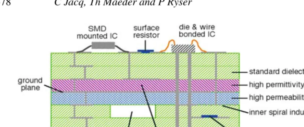
Figure 1. 3-D structuration of LTCC and example of achievable features.
earth aluminium borosilicate materials (in fact very similar to those of modern thick-film dielectrics), and exhibit outstanding chemical and thermal stability, as well as excellent high-frequency properties (Nishigaki & Fukuta 1989, Rauscher & Roosen 2007, Jones et al 2000, Dziedzic 2000). LTCC comes as unfired ‘green’ sheet (tape) of various thicknesses (ceramic powder with polymer binder). Each sheet is shaped and screen-printed with conductive, resis-tive or other pastes. Finally, the sheets are pressed and fired together. Firing of LTCC is done in air below 900◦C, which makes it compatible with silver conductors and thus leads to a relatively low-cost process. As the module is fired essentially once, LTCC technology is especially advantageous for complex devices having many layers.
In addition to the standard LTCC dielectric materials, compatible tapes with high electric permittivity or magnetic permeability are available, and can be used to integrate capacitors and inductors (figure 1). Moreover, 3D hermetic structures, internal membranes cavities and channels are also possible.
The following section describes representative applications of both classical thick-film and LTCC technologies in harsh environments.
2. Representative applications 2.1 Liquid level sensor
A thick-film liquid level sensor has been developed for continuous immersion in water, mildly aggressive aqueous solutions and fuels (figure 2), for remote tank telemetry applications (Huba 2004). Level is measured by means of an absolute thick-film piezo-resistive pressure sensor. The thick-film module at the heart of the sensor consists of three elements: (1) a base comprising only interconnections, (2) the pressure sensitive membrane and (3) the sensor electronics. Protection of the electronics and the cable attachment is achieved by an epoxy
Figure 2. Liquid level sensor — ceramic module.
Figure 3. Packaged liquid level sensor.
potting compound, which covers the corresponding half of the module, with the other half, carrying the membrane, being left free standing. This construction effectively decouples the membrane from the stresses induced by the potting, avoiding drift of the signal (figure 3).
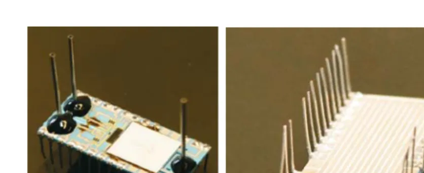
The sensitive membrane (figure 4) is based on a very thin deformable alumina substrate (0·17 mm) with a piezo-resistive thick-film Wheatstone bridge that also includes resistors for coarse offset adjustment. The membrane is attached to the base by a ‘flip chip’ glass sealing process, which simultaneously accomplishes three functions: (i) hermetic separation of the sensor cavity and resistors from the outside environment, (ii) definition of the deformable area of the membrane (e.g. the area that is not sealed), and (iii) electrical connection of the sensing bridge to the base, by means of special conductive glass pads. This one-step sealing process is compatible with low-cost batch production.
2.2 Jet engine AMB sensor
For active magnetic bearing (AMB) applications as position sensors (Burdet 2006), inductive and eddy current sensors are widely used. They are typically installed as several coils mounted
Figure 4. Membrane with sealing-glass ring and assembled membrane.
Figure 5. Diagram and photograph (without top dielectric layer) of the AMB sensor.
symmetrically around the rotor. For jet engine eddy current radial position sensors, the severe condition is the high temperature, together with potentially aggressive exhaust gases. Thick-film technology, which has proven its capability to work at high temperature, for example in applications such as heating elements (Tait et al 1994) and high temperature electronics packaging (Chen et al 2000), was used to fabricate silver coils printed on ceramic substrates (Burdet et al 2006).
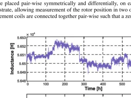
An excitation coil (figure 5), which is printed on a ceramic substrate, surrounds a non-magnetic metallic rotor and creates eddy currents on the rotor surface. Four measurement coils are placed pair-wise symmetrically and differentially, on each cardinal directions of the substrate, allowing measurement of the rotor position in two orthogonal directions. The measurement coils are connected together pair-wise such that a zero signal is obtained when
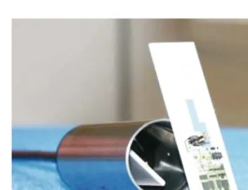
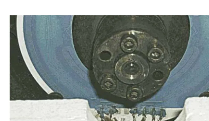
Figure 7. Jet engine AMB sen-sor mounted on the rotor (Burdet 2006).
the rotor is centred. When the rotor is not centred, a voltage appears on the measuring coils. This signal is synchronous with the excitation signal and can be thus demodulated in order to obtain a suitable position signal. Printing a coil on a substrate means that at least two conducting layers are needed in order to have the connectors outside the inductor. A long outside track was added for resistive temperature measurement. The sensor shown here is not complete, in order to keep the 2ndlayer of the coils visible. In the complete version, the coils
are covered with dielectric, leaving only the connecting pads exposed.
Long-term measurements showed a good stability of this technology at high temperature. Use of an AC current source at 900 kHz and high impedance amplifiers enabled the sensor temperature compensation. The sensor response was measured from room temperature up to 600◦C (figure 6). Finally, a solution is given to mount radial sensor ceramic disk into a metallic housing (figure 7).
2.3 Hydrostatic high-pressure sensor
For this sensor, the stability, hermeticity, and capability for 3D multilayer circuits of LTCC have been used to fabricate a hydrostatic high pressure (≥ 1 to 2 kbar) sensor (Maeder
et al 2007a). In this pressure range, sensors using classical deformable structures such as
membranes progressively run into difficulties, due to the decreasing ratio between the available sensing strain on the outer membrane surface and the maximal material strain experienced on the pressurised side. In this novel concept, thick-film piezo-resistors have been embedded hermetically in LTCC beams whose high-pressure side is directly exposed to the pressure. To be measured. The actual device is depicted in figure 8 (transverse and cross sections).
Figure 9. Fired LTCC sensing module (left), and layout of core layers (right).+/− = positive/ negative supplies;s + /− = positive/negative bridge outputs (Maeder et al 2007a).
A metal body compatible with any type of mounting (screwing, welding, etc.) is fabricated, and two cavities (pressure and reference) are drilled at each end, linked by a hole just large enough to accommodate the sensing element. This element, best fabricated as a stick-shaped LTCC module with buried resistors in a Wheatstone bridge configuration, is then inserted into the hole, and bonded by filling the remainder of the cavity with a strong adhesive such as epoxy.
This design has several advantages. First, the sensing materials are nominally in isostatic compression — pressure capacity is mainly limited by the adhesive feedthrough. Moreover, direct vertical loading of the resistor gives a high sensitivity, due to a much lower elastic modulus (60. . . 85 GPa) (Santo-Zarnik et al (2003), White (1988)) than the substrate 110 GPa for LTCC and 300. . . 340 GPa for Al2O3 (Santo-Zarnik et al 2003; White 1988). This is
also seen in force sensors where piezo-resistors are directly loaded in compression (Puers
et al 1987). LTCC has two advantages over alumina. (i) Using a buried-resistor configuration
reliably protects the bridge against aggressive media, and (ii) its much smaller elastic modulus gives a larger output signal.
The LTCC pressure sensing module, depicted in figure 9, was designed with length, width and height of 58, 2·2 and 0·85 mm, respectively. A four-layer configuration was used: 1) bottom lid; 2) bottom sensing half-bridge; 3) top sensing half-bridge; 4) top lid. Thus, the sensing resistors are fully buried in the LTCC, and the resulting ‘stick’ is very thin. This is important, as a small feedthrough hole is more reliable and allows operation at higher pres-sures.
The observed sensor response (figure 10) is very close to the values calculated from the LTCC and piezo-resistor materials properties (shifted only by the bridge offset), and is much higher than the nominal bridge signal of thick-film sensors using membrane structures (around 3 mV/V). Tests have shown drift to be negligible up to at least 1200 bar, which is expected from the isostatic loading.
Figure 10. Sensor response under pressure and expected value (Maeder et al 2007a).
Figure 11. Chemical liquid microreactor, view on both sides, heating by conductor meander (bottom side).
2.4 Chemical liquid microreactor
Fabrication of a 3D LTCC structure has been used here to produce a fluidic device: a chemical liquid microreactor (Maeder 2006) (figure 11), which combines both a fluidic and a screen-printed electrical circuit. The channels have been fabricated by laser cutting of intermediate layers of green tapes, followed by lamination and firing.
The reactor, which is heated using a conductive meander on the bottom side of an alumina carrier (figure 11), is divided into several parts (figure 12, left), with liquid flowing from left to right. First, the reactants coming through the inlet ports pass through a preheating meander, which allows them to reach thermal equilibrium with the microreactor body. Next, the flow of each reactant is measured by a thermal flow sensor. Then, both reactants enter the reaction zone separately, meet and react in a meander, which ensures effective plug flow (Schneider
et al 2004). Thermistors allow the measurement of the temperature rise of the reaction zone
with respect to the reactor body, and thus can be used to determine the heat of reaction. This calorimetric measurement is calibrated by the means of a separate reactor heater resistor. Comparing with a previous version fabricated using classical thick-film technology and glass sealing (Figure 12, right) (Schneider et al 2004, Schneider 2004), the much higher complexity allowed by LTCC for fluidic devices becomes evident.
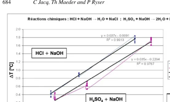
Figure 13 depicts the reaction zone temperature rise vs. the generated heat (calculated from the reactant compositions and flows), for two classical acid-base reactions. Good agreement is seen between measurements and calculated values, accounting for some offsets due to parasitic heat losses in this prototype device.
Figure 12. Chemical LTCC microreactor/microcalorimeter elements (left), compared to its classical thick-film predecessor (right). The fluidic layout is shown superimposed in semi-transparent mode.
Figure 13. Calorimetric measurement of two acid–base reactions.
2.5 Gas viscosity and thermal conductivity sensor
Another fluidic device (Maeder et al 2006, 2007b) is used for identification of natural gas mixtures, by measurement of viscosity and thermal conductivity, which allows determination of the Wobbe index, and thus optimisation of the combustion of gas-fired heaters. The sensor (figure 14) comprises 3 modules: (1) a heated cavity to generate a controlled pressure rise, (2) a pressure sensor made of a membrane, connected to the heater, which measures the pressure variation, and (3) a flow resistance, which is a meander structure connected to the gas inlet.
Two separate 3D fabrication techniques of LTCC have been used to fabricate this device (Maeder et al 2007c): (i) laser cutting and lamination, as in the case of the microreactor, for the heater/cavity module, and (ii) the carbon sacrificial layer method for the rest of the fluidic circuit (membrane, meander and connecting channels). In the latter case, a carbon paste is screen printed in an inner layer of the LTCC stack, and is burned off during firing of the
Figure 14. Wobbe sensor (mem-brane+ meander integrated into sensor base).
LTCC. This is a very powerful method that allows to create narrow channels (e.g. 10µm), which are well-suited for creating a well-controlled resistance to gas flow, and large and flat membranes allowing measurement of low pressures, provided the process parameters are tightly controlled (Birol et al 2007).
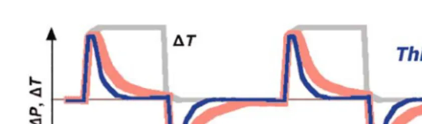
Viscosity is measured by periodically turning the heater on and off. This results in a very fast (e.g. 1 s) change of the gas temperature in the cavity, and a corresponding differential pressure peak (figure 15). This pressure, which is monitored by the membrane, relaxes by controlled leakage through the meander, and viscosity is directly proportional to this relaxation time. The pressure is measured thermally, through the heat losses of a thermistor placed in the center of the membrane, which are dependent on both differential pressure and thermal conductivity (figure 16). Thermal conductivity measurement is simply carried out at zero differential pressure, e.g. when the pressure inside the cavity is fully relaxed.
The device has been tested with three gases: butane, air and helium (figure 16). Mea-surements done on optimised sensors are reproducible, and gases may be differentiated both through thermal resistance and viscosity (pressure relaxation time).
3. Conclusions and outlook
Classical thick-film technology is advantageous in terms of cost and mechanical strength for relatively simple structures. Here it was applied to a ‘flip-chip’ immersed pressure sensor and an inductive eddy current position sensor for jet engine active magnetic bearings.
Figure 16. Thermal resistance (thermistor to base) vs. membrane displacement, for 3 different gases and different applied voltages on the thermistor (Maeder et al 2007b).
and a gas viscosity sensor.
The ever increasing requirements for energy efficiency, process control and reliability create needs for devices operating under severe conditions, in industries such as deep-well drilling, aerospace, automotive, and chemical. Both classical thick-film and LTCC ceramic-based technologies are ideal platforms to meet these demands in an efficient, reliable and cost effective way.
References
Barlow F D, Elshabini 2007 A Ceramic interconnect technology, Handbook CRC Press
Birol H, Maeder T, Ryser P 2007 Application of graphite-based sacrificial layers for fabrication of LTCC (low temperature co-fired ceramic) membranes and micro-channels. J. Micromechanics and Microengineering 17: 50–60
Burdet L 2006 Active Magnetic Bearing Design and Characterization for High Temperature Appli-cations, Th`ese N◦3616, EPFL, Lausanne
Burdet L, Maeder T, Siegwart R, Buehler P, Aeschlimann B 2006 Thick-film radial position sensor for high temperature active magnetic bearings, Proceedings, 10th International Symposium on Magnetic Bearings (ISMB 10), Martigny (CH), 555–559
Coleman M V 1982 Thick-film materials for hybrids. The Radio and Electronic Engineer 52(5): 227–234
Chen L Y, Hunter G W, Neudeck P G 2000 Thin and thick film materials based interconnection tech-nology for 500◦C operation, Transaction of First International AVS Conference on Microelectronics and Interfaces
Dziedzic A, Golonka L J, Kita J, Kozlowski J M 2000 Macro- and microstructure of LTCC tapes and components, Proceedings, IMAPS 2000, Poland
Huba Control A G 2004 Pressure sensor for immersion probe has converter for converting bending caused by pressure into signal and has amplification electronic that is in contact with the converter, Gebrauchsmusterschrift DE 20 2004 004 671 U1, Germany
Jones W K, Liu Y, Larsen B, Wang P, Zampino M 2000 Chemical, structural and mechanical proper-ties of the LTCC tapes, Proceedings, International Symposium on Microelectronics IMAPS-2000, 669–674
Maeder T 2006 Integrated calorimetric microreactor in low-temperature co-fired ceramic (LTCC) technology, STK Calorim´etrie Fribourg, Switzerland 1/43, 06–08
Maeder T, Jacq C, Saglini I, Corradini G, Straessler S, Birol H, Ryser P 2006 LTCC thermal gas viscometer — Heater module, Proceedings, European Microelectronics and Packaging Symposium, Terme ˇCateˇz, Slovenia, IMAPS pp. 61–66
Maeder T, Afra B, Fournier Y, Johner N, Ryser P 2007a LTCC ultra high isostatic pressure sensors, Proceedings, 16th IMAPS – EMPC, Oulu, Finland, 375–380
Maeder T, Dumontier N, Jacq C, Corradini G, Ryser P 2007b LTCC Gas-Viskosit¨atssensor, Deutsche IMAPS-Konferenz, M¨unchen, Germany
Maeder T, Fournier Y, Wiedmer S, Birol H, Jacq C, Ryser P 2007c 3D structuration of LTCC/thick-film sensors and fluidic devices, Proceedings, 3rd International Conference on Ceramic Interconnect and Ceramic Microsystems Technologies (CICMT), Denver USA, THA13
Nishigaki S, Fukuta J 1989 Low-temperature, co-fireable, multilayered ceramics bearing pure-Ag conductors and their sintering behaviour, Ceramic Substrates and Packages for Electronic Appli-cations. Advances in Ceramics 26: 199–215
fast exothermic reactions in liquid phase: Characterization of the system, Chemical Eng. J. 101: 241–250
Schneider M A 2004 Development of a novel microreactor-based calorimeter for the study of fast exothermal reactions in liquid phase, thesis no 3069, EPFL, Switzerland
Santo Zarnik M, Belaviˇc D, Macek S, Kita J 2003 Modelling of a piezo-resistive ceramic pressure sensor, Proceedings, MIDEM 2003, Ptuj, SI
Tait R B, Humphries R, Lorenz J 1994 Thick film heater elements and temperature sensors in modern domestic appliances. IEEE Transactions on Industry Applications 30: 573–577
White N M 1988 A study of the piezo-resistive effect in thick-film resistors and its application to load transduction, thesis, University of Southampton, Faculty of Engineering and Applied Science White N M, Turner J D 1997 Thick-film sensors: past, present and future, Proceedings, 14th
International Conference on Solid-State Sensors, Actuators and Microsystems – Transduc-ers/Eurosensors’07 107–111