Publisher’s version / Version de l'éditeur:
Vous avez des questions? Nous pouvons vous aider. Pour communiquer directement avec un auteur, consultez la
première page de la revue dans laquelle son article a été publié afin de trouver ses coordonnées. Si vous n’arrivez pas à les repérer, communiquez avec nous à [email protected].
Questions? Contact the NRC Publications Archive team at
[email protected]. If you wish to email the authors directly, please see the first page of the publication for their contact information.
https://publications-cnrc.canada.ca/fra/droits
L’accès à ce site Web et l’utilisation de son contenu sont assujettis aux conditions présentées dans le site LISEZ CES CONDITIONS ATTENTIVEMENT AVANT D’UTILISER CE SITE WEB.
Proceedings of 2006 Fire Suppression and Detection Research Application Symposium: 01 February 2006, Orlando, FL., U.S.A., pp. 1-5, 2006-02-01
READ THESE TERMS AND CONDITIONS CAREFULLY BEFORE USING THIS WEBSITE.
https://nrc-publications.canada.ca/eng/copyright
NRC Publications Archive Record / Notice des Archives des publications du CNRC :
https://nrc-publications.canada.ca/eng/view/object/?id=48631385-c6d9-406c-bb14-0d21031a5029 https://publications-cnrc.canada.ca/fra/voir/objet/?id=48631385-c6d9-406c-bb14-0d21031a5029
NRC Publications Archive
Archives des publications du CNRC
This publication could be one of several versions: author’s original, accepted manuscript or the publisher’s version. / La version de cette publication peut être l’une des suivantes : la version prépublication de l’auteur, la version acceptée du manuscrit ou la version de l’éditeur.
Access and use of this website and the material on it are subject to the Terms and Conditions set forth at
Compressed-air-foam (CAF) system for fire protection of power transformers
http://irc.nrc-cnrc.gc.ca
Compressed-air-foam (CAF) system for fire protection of
power transformers
N R C C - 4 8 3 2 0
K i m , A . ; C r a m p t o n , G .
A version of this paper is published in / Une version de ce document se trouve dans: Proceedings of 2006 Fire Suppression and
Detection Research Application Symposium, Orlando, FL., Feb. 1-3, 2006, pp. 1-5
COMPRESSED-AIR-FOAM (CAF) SYSTEM FOR FIRE PROTECTION OF POWER TRANSFORMERS
by
Andrew Kim* and George Crampton
Fire Research Program, Bldg. M-59, Institute for Research in Construction,
National Research Council of Canada 1200 Montreal Road,
Ottawa, Ontario, K1A 0R6, Canada
e-mail: [email protected]
INTRODUCTION
Power transformers play an important role in making communities function by
distributing the power. Power transformers deal with high voltage electric power and there is a strong possibility of accidental fire incidents in the power transformer. Because of the high possibility of fire occurrence and the important role they play in the maintenance of normal life in the community, the power transformers must have a proper fire protection system in place to provide the best fire protection.
Current fire protection systems for power transformers using sprinklers require a large quantity of water, which may cause a problem to their electrical function as well as creating water damage and environmental effects. Also, clean-up after fire suppression is another problem. Power transformers contain hazardous materials, and any run-off water from the fire suppression activities has to be collected. It is a costly proposition to provide infrastructure to contain the run-off water resulting from the fire suppression of a power transformer. Another fire protection approach is to use an air-aspirated foam system. However, current air-aspirated foam systems produce poor quality foam, therefore a large quantity of foam is needed to provide proper fire protection to the power transformers. This again creates a clean-up problem
afterwards, delays the re-start of the power transformers and prolongs the power shutdown to the community.
The National Research Council of Canada (NRC) has developed a means of producing Compressed-Air-Foam (CAF) in a fixed pipe system. This system provides superior quality foam with uniform distribution and high momentum. In previous studies, NRC has proven by full-scale tests that CAF has superior fire suppression performance compared to current foam or sprinkler systems. Therefore, CAF may be an ideal solution in providing fire protection for
*
Author to whom correspondence should be addressed: E-mail; [email protected], Phone #; (613) 993-9555, Fax #; (613) 954-0483
power transformers, with its superior fire suppression performance and low water requirement, thus minimizing the clean-up problem.
Recently, a study was carried out to develop a CAF distribution system and to evaluate the fire suppression capability of the CAF system for the protection of power transformers. This paper describes the experimental facility, including the power transformer mock-up and
instrumentation, and presents experimental results of the fire suppression capability of the CAF system for power transformer protection.
EXPERIMENTAL SET-UP AND PROCEDURE
A series of full-scale fire tests was carried out to determine the fire suppression capability of the CAF system using a power transformer mock-up facility. Also, one full-scale fire test was carried out with a traditional water deluge system, to compare the fire suppression capabilities of the newly-developed CAF system with the water deluge system in providing fire protection for power transformers.
Power transformer mock-up test facility
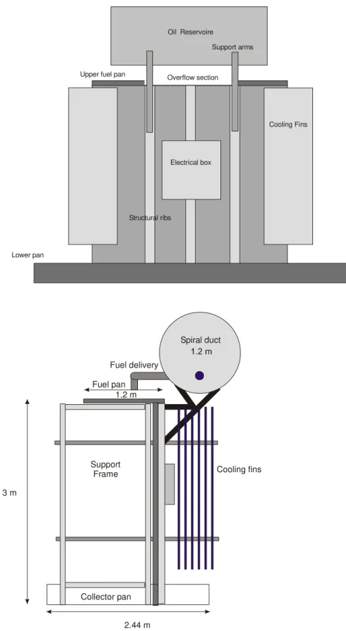
A mock-up power transformer was constructed for the experimental study. The power transformer mock-up was constructed of 20 gauge formed steel panels fastened to a tubular steel frame 3.9 metres wide by 1.2 metres deep by 3 metres high. This was a scale representation of an actual power transformer at Hydro Quebec’s Berri Station in Montreal. The mock-up was built to represent the front half of the transformer including the oil reservoir and cooling fins. The front half was chosen because it represented more severe challenges to the fire protection systems than the back half, due to more obstacles on the transformer and also a greater fire hazard with a larger amount of fuel. Figure 1 shows the schematic drawing of the power transformer mock-up.
The fire scenario envisioned in the power transformer fire was an explosion in the main transformer body due to internal arcing, resulting in the blowing of a high voltage bushing through the top of the power transformer or the rupturing of the transformer oil reservoir leaking oil onto the top of the transformer. The oil on top of the transformer would be involved in fire and overflowing over the side and front of the power transformer, producing cascading fires as well as pool fires around the bottom of the transformer. This worst case fire scenario for the power transformer was simulated in this experimental study.
Several fire pans were constructed to provide the fire hazard on the top, bottom centre and sides of the mock-up. The top pan had a cut out section along the front wall to produce a
cascading fire 1.8 metres wide under the reservoir and between the cooling fins. This would be the area considered to be the most challenging for a fire protection system. The oil reservoir was simulated by a 1.2 m diameter and 2.1 m long cylindrical steel duct. A 5 cm steel pipe with a length of 9 m was used to safely provide the oil to the top pan from a 205 litre heated drum. The oil was delivered to the top pan by gravity fed through the pipe with a flow rate of approximately 80 litres/minute. The oil in the top pan then overflowed down the face of the mock-up.
Instrumentation
Four thermocouples were installed on the power transformer mock-up. One was located over the center of the top pan and the second one was located in the middle of the space between the oil reservoir and the main body of the transformer. The other two thermocouples were located beside the two fire detectors of the water deluge system, which was installed in the mock-up for experimental evaluation. This water deluge system had the same configuration as the one actually installed in a Montreal sub-station for the power transformers protection.
Heat flux meters were used to monitor the radiation fluxes from the power transformer fires. A mast containing 5 heat flux meters was located 6 m from the front corner of the mock-up. The bottom heat flux meter was located 2.5 m above the floor, and the second one was 3.75 m above, a third one was 4.375 m above, a fourth one was 5 m above, and the top one was 6.25 m above the floor. All heat flux meters, except the middle one, were placed 6 m away from the front corner of the mock-up. The middle heat flux meter was 5.375 m away from the front corner of the mock-up.
Two video cameras were used for a visual record of the experiments. One video camera was located at 4 m above the top front corner of the mock-up and the second one was at ground level near the front corner.
Test fuels
Tests were conducted using electrical insulating oil typically used in power transformers. The electrical insulating oil used in the tests was Voltesso 35, which was produced by Imperial Oil. Voltesso 35 has a density of 877 kg/m3 at 15ºC, and its flash point is 150ºC. The normal operating temperature of the insulating oil in the power transformer is 75ºC. Therefore, during the experiments, the electrical insulating oil was pre-heated to approximately 75ºC before it was ignited for the test.
Suppression systems
A CAF distribution system was developed for the power transformer protection. Several CAF configurations were studied to determine the most efficient way to distribute foam around the vertical and horizontal obstacles of the power transformer. The final CAF system selected for this project incorporated two types of nozzles; Large Flow Gear Driven Rotary (GDR) Nozzle and Small Flow Turbine Action Rotary (TAR) Nozzle. The TAR nozzles were utilized in 3 to 8 nozzle CAF configurations in the tests for the fire suppression of the mock-up test facility. The GDR nozzles were utilized in 2 nozzle configuration for the mock-up facility. CAF was
generated using Fire Flex’s ICAF generating system.
For the 4 nozzle CAF system, one TAR nozzle was located on each of the two sides of the mock-up and two TAR nozzles were used to provide protection on the front of the mock-up. In the 3 nozzle system, one nozzle was used for each side of the mock-up and only one nozzle was used to provide protection on the front of the mock-up. For the 8 nozzle CAF system, two nozzles were located on each side of the mock-up (one nozzle near the top, spraying onto the top
of the mock-up, and one nozzle below the top, spraying onto the side wall) and four nozzles were used to provide protection on the front of the mock-up (two nozzles at the top edge spraying toward the top side of the front wall and oil reservoir, and two nozzles below the top spraying onto the front wall).
For the GDR nozzle CAF system, one GDR nozzle was located on the left side of the mock-up and one GDR nozzle was located at the front of the mock-up. Both nozzles were placed above the top level of the mock-up, spraying down in an angle. The right side of the mock-up was not protected in these tests with the assumption that that side of the mock-up can be protected by a CAF system protecting the back half of the power transformer.
A test was also conducted using a water deluge system as a comparison to the CAF system. The water deluge system tested was similar to the one installed in an actual power transformer at Hydro Quebec’s Berri Station in Montreal. The deluge system consisted of a ring of 21 nozzles, with a total flow rate of 910 litres/min.
Test procedure
The test fuel in the top pan was ignited at time zero, then the fuels in the side pan and front pan were ignited in sequence. At 30 s, the fuel was allowed to flow onto the top pan with a flow rate of approximately 80 litres/minute. This resulted in an overflow of the fuel from the top pan down the front face of the mock-up onto the front pan, causing a cascading fire on the front face of the mock-up. At approximately 1 min 10 s, when the flame from the front pan was fully developed with a flame height reaching the top of the mock-up and flames attacking the side of the oil reservoir, the CAF or water deluge suppression system was activated to control the fire. The suppression action was maintained until the fire was completely extinguished. During the test, the solution flow rate of the suppression system, temperature readings at several points of the mock-up, radiation fluxes from the fire, fire suppression time (99% extinguishment) and complete extinguishment time were recorded.
RESULTS AND DISCUSSION
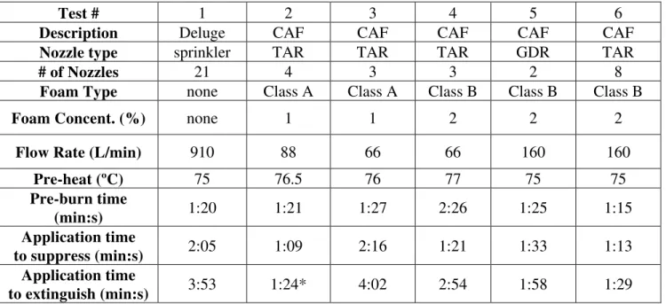
Table 1 shows the summary of the test conditions and fire suppression performance results of the water deluge and CAF systems for power transformer protection.
In Test #1, the water deluge system extinguished the test fire in 3 min 53 s. The water deluge system had 21 spray nozzles, and the total flow rate was 910 L/min. The test fuel was transformer oil (Voltesso 35), which was pre-heated to 75ºC before the start of the test. The water deluge system took 2 min 5 s to control (99% extinguishment, obtained from heat flux meter data; heat flux value is 1% of the peak heat flux value) the fire, eventually extinguishing it completely in 3 min 53 s. This fire suppression performance of the water deluge system will be the basis of comparison for all the CAF systems tested in this study.
In Test #2, 4 TAR nozzles were used in the CAF system. Total flow rate was 88 L/min, and Class A foam concentrate was used at 1%. The test fuel was transformer oil, pre-heated to 76.5ºC. The CAF system controlled the fire in 1 min 9 s and extinguished most of the fire,
except one small pan on the side, in 1 min 24 s. The foam distribution was not ideal, and the small side pan did not receive proper foam distribution density and was left burning. In subsequent tests, the side nozzle of the TAR CAF system was adjusted to improve its foam distribution.
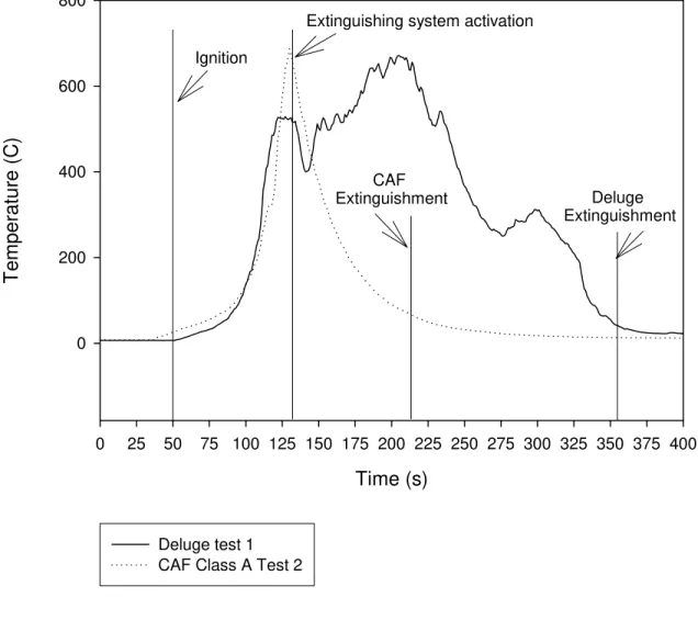
Figure 2 shows the temperatures measured at the space between the front top edge and the oil reservoir of the transformer mock-up during fire suppression by the water deluge system (Test #1) and CAF system (Test #2). These temperatures indicate the flame condition on the front face of the mock-up. The figure shows that there was an initial fire flare up with the water deluge system, whereas with CAF, there is a substantial decrease in temperature as soon as the CAF system was activated.
In Test #3, 3 TAR nozzles were used in the CAF system, with the angle of the side nozzle adjusted to improve the foam distribution. The 3 TAR nozzle CAF system had only one nozzle at the front of the mock-up instead of two nozzles in Test #2. The total flow rate was 66 L/min, and the foam concentrate and the test fuel were the same as in Test #2. The CAF system
controlled the fire in 2 min 16 s and extinguished the fire in 4 min 2 s. The test showed similar fire suppression performances by the CAF system with 3 TAR nozzles (test #3) and the water deluge system (Test #1), however, the CAF system used less than 8% of the water flow rate of the water deluge system.
Test #4 was similar to Test #3, except Class B foam concentrate was used instead of Class A. Also, in Test #4, the pre-burn time was extended to 2 min 26 s, which made the fire to grow bigger and produced a much more challenging fire scenario for the suppression system. Even with such a large fire, a 3 TAR nozzle CAF system, using 2% Class B foam concentrate, extinguished the transformer fire in 2 min 54 s.
Test #5 used a 2 GDR nozzle CAF system. The transformer oil was pre-heated to 75ºC, and was allowed a pre-burn of 1 min 25 s. The CAF system using 2% Class B foam concentrate controlled the fire in 1 min 33 s and extinguished it in 1 min 58 s.
In Test #6, an 8 TAR nozzle CAF system was used. Transformer oil was pre-heated to 75ºC, and was allowed a pre-burn of 1 min 15 s. The CAF system using 2% Class B foam concentrate controlled the fire in 1 min 13 s and extinguished it in 1 min 29 s.
CONCLUSION
CAF systems with 3 or 4 TAR nozzles and with 2 GDR nozzles were developed to protect power transformers. A series of full-scale fire tests was conducted using a test mock-up, which represents a one half section of a power transformer, to measure the effectiveness of water deluge and CAF systems in extinguishing a large simulated power transformer fire, using Class A and Class B foam concentrates.
The test results clearly showed that the CAF system, either with 2 large GDR nozzles or with 3 or 4 small TAR nozzles, performed much better than the water deluge system with 21 sprinkler heads. The CAF system with 3 TAR nozzles using 1% Class A foam concentrate
extinguished the test fire in 4 min 2 s, which is almost the same as the results of the water deluge system. However, the 3 TAR CAF system used less than 8% of the total water flow rate of the water deluge system.
The CAF system with 2 GDR nozzles using 2% Class B foam concentrate extinguished the test fire in 1 min 58 s, which is almost one half of the extinguishment time of the water deluge system. And, the water usage was less than 18% of the total flow rate of the water deluge system. The CAF system with 8 TAR nozzles using 2% Class B foam concentrate extinguished the test fire in 1 min 29 s, with far less water requirement than the water deluge system.
The study clearly shows that a CAF system can provide necessary fire protection for power transformers, more effectively with much less water requirement, compared to a traditional water deluge system.
ACKNOWLEDGEMENT
Authors would like to acknowledge the assistance of Michael Ryan in conducting the tests. Authors would also like to express deep appreciation to Mr. Jean-Pierre Asselin and Mr. Raymond Quenneville of Fire Flex Systems Inc. for their assistance in the CAF testing.
Table 1 Summary of Test Conditions and Results
Test # 1 2 3 4 5 6
Description Deluge CAF CAF CAF CAF CAF
Nozzle type sprinkler TAR TAR TAR GDR TAR
# of Nozzles 21 4 3 3 2 8
Foam Type none Class A Class A Class B Class B Class B
Foam Concent. (%) none 1 1 2 2 2
Flow Rate (L/min) 910 88 66 66 160 160
Pre-heat (ºC) 75 76.5 76 77 75 75 Pre-burn time (min:s) 1:20 1:21 1:27 2:26 1:25 1:15 Application time to suppress (min:s) 2:05 1:09 2:16 1:21 1:33 1:13 Application time to extinguish (min:s) 3:53 1:24* 4:02 2:54 1:58 1:29
* pan on the side did not receive foam and was left burning
Cooling Fins
Structural ribs
Oil Reservoire
Support arms
Electrical box Upper fuel pan
Lower pan Overflow section vii Spiral duct Cooling fins Support Frame Fuel delivery Fuel pan Collector pan 3 m 1.2 m 2.44 m
Side view Transformer Setup
Scale 10mm = 0.3 m
Plume temperature (C)
Deluge and CAF
Time (s) 0 25 50 75 100 125 150 175 200 225 250 275 300 325 350 375 400 T e mper atur e ( C ) 0 200 400 600 800 Deluge test 1 CAF Class A Test 2
Extinguishing system activation Ignition
CAF
Extinguishment Deluge
Extinguishment