https://doi.org/10.1061/41171(401)37
READ THESE TERMS AND CONDITIONS CAREFULLY BEFORE USING THIS WEBSITE. https://nrc-publications.canada.ca/eng/copyright
Vous avez des questions? Nous pouvons vous aider. Pour communiquer directement avec un auteur, consultez la
première page de la revue dans laquelle son article a été publié afin de trouver ses coordonnées. Si vous n’arrivez pas à les repérer, communiquez avec nous à PublicationsArchive-ArchivesPublications@nrc-cnrc.gc.ca.
Questions? Contact the NRC Publications Archive team at
PublicationsArchive-ArchivesPublications@nrc-cnrc.gc.ca. If you wish to email the authors directly, please see the first page of the publication for their contact information.
NRC Publications Archive
Archives des publications du CNRC
This publication could be one of several versions: author’s original, accepted manuscript or the publisher’s version. / La version de cette publication peut être l’une des suivantes : la version prépublication de l’auteur, la version acceptée du manuscrit ou la version de l’éditeur.
For the publisher’s version, please access the DOI link below./ Pour consulter la version de l’éditeur, utilisez le lien DOI ci-dessous.
Access and use of this website and the material on it are subject to the Terms and Conditions set forth at
Effects of thermal expansion and support restraints on performance of composite floors in fire
Mostafaei, H.; Alfawakhiri, F.
https://publications-cnrc.canada.ca/fra/droits
L’accès à ce site Web et l’utilisation de son contenu sont assujettis aux conditions présentées dans le site LISEZ CES CONDITIONS ATTENTIVEMENT AVANT D’UTILISER CE SITE WEB.
NRC Publications Record / Notice d'Archives des publications de CNRC:
https://nrc-publications.canada.ca/eng/view/object/?id=55e25633-2103-4d82-aafd-9b108bcbaf9d https://publications-cnrc.canada.ca/fra/voir/objet/?id=55e25633-2103-4d82-aafd-9b108bcbaf9d
http://www.nrc-cnrc.gc.ca/irc
Effe c t s of t he rm a l e x pa nsion a nd support re st ra int s on pe rform a nc e of c om posit e floors in fire
N R C C - 5 3 5 3 9
M o s t a f a e i , H . ; A l f a w a k h i r i , F .
A p r i l 2 0 1 1
A version of this document is published in / Une version de ce document se trouve dans:
The Structures Congress, Las Vegas, Nevada, April 14-16, 2011, pp. 1-12
The material in this document is covered by the provisions of the Copyright Act, by Canadian laws, policies, regulations and international agreements. Such provisions serve to identify the information source and, in specific instances, to prohibit reproduction of materials without written permission. For more information visit http://laws.justice.gc.ca/en/showtdm/cs/C-42
Les renseignements dans ce document sont protégés par la Loi sur le droit d'auteur, par les lois, les politiques et les règlements du Canada et des accords internationaux. Ces dispositions permettent d'identifier la source de l'information et, dans certains cas, d'interdire la copie de documents sans permission écrite. Pour obtenir de plus amples renseignements : http://lois.justice.gc.ca/fr/showtdm/cs/C-42
Effects of Thermal Expansion and Support Restraints on Performance of Composite Floors in Fire
H. Mostafaei1, F. Alfawakhiri2 1
Research Officer, National Research Council Canada, M-59, 1200 Montreal Rd, Ottawa, ON K1A 0R6; Hossein.Mostafaei@nrc-cnrc.gc.ca
2
Senior Engineer, American Iron and Steel Institute, 594 Windham Lane, Naperville, IL 60563; falfawakhiri@steel.org
ABSTRACT
This paper presents results of a numerical study on the effects of thermal expansion and support restraint conditions on the performance of composite floors in fire. Previously, two full-scale composite floor specimens were tested to investigate factors, such as the supports restraint conditions, that affected the failure of the World Trade Center buildings’ floors. Although higher fire resistance was expected for the restrained floors, the test results showed higher fire resistance rating for the unrestrained floor specimen. The purpose of this research was to understand the rationale behind these results numerically. The structural analysis software SAFIR was employed to evaluate the response of the composite floor specimens in fire, such as strain and stress distributions and floor deflection. The results show that the concrete spalling during the first hour of the test for the restrained specimen would have been due to concrete compression failure caused by the restraint condition and thermal expansion.
INTRODUCTION
Since the 9/11 disaster, various studies have been carried out to investigate the performance and collapse simulation of the World Trade Center (WTC) buildings subjected to the impact of the aircrafts and the following fire. Significant efforts have been extended to investigate performance of the WTC’s building structures in the fire (NIST, 2005). Although damage from the impacts could have had considerable effects on the structural response of the two towers, the WTC’s towers had not collapsed in fire shortly after the impacts. In fact, the WTC’s north tower burned for 102 minutes, after it was hit by the aircraft, before it collapsed. As for the WTC south tower, the collapse of the structure occurred after burning for 56 minutes in fire. Therefore, fire was considered as a major factor in the collapse of the two towers.
One of the experimental studies was carried out by the National Institute of Standards and Technology (NIST) on the fire resistance and performance of the WTC’s towers composite floors (Gross et al., 2005). A main objective of this experimental study was to explore “why and how WTC towers collapsed following the initial impacts of the aircraft and to determine factors that most influenced the buildings’ composite floors failure”. Two full-scale composite floors were tested by NIST at the Underwriters Laboratories of Canada fire testing facility in Toronto (ULC). In order to investigate the support restraining effects on fire performance of the floors, one specimen was tested with restrained supports and the other - with unrestrained supports conditions. Although higher fire resistance was expected for the restrained floors, the test results showed higher
fire resistance for the unrestrained full-scale floor specimen compared to the restrained floor. Observations during the two tests indicated more damage and spalling of concrete for the restrained floor specimen compared to the unrestrained specimen.
This paper provides results of a numerical study for the two floor test assemblies. The main objective is to investigate and understand the failure mechanism of these two full-scale specimens, which simulate the WTC’s towers composite floors. The analysis was done using the SAFIR structural analysis package (Franssen, 2007). Furthermore, a post-processor was developed to generate stress and strain profiles on the cross-sections of the floors’ elements.
FLOOR SYSTEM OF THE WTC TOWERS
The World Trade Center towers had a steel/concrete composite floor system. It consisted of a concrete slab and steel trusses supported at the two truss ends between the building’s core columns and exterior wall columns. The steel trusses were installed in pairs with 2.0 m spacing, on center, with a nominal clear span of either 18.3m or 10.7m. Both top and bottom chords were made of double steel angles. Double round bars were used as the diagonal members of the trusses. The diagonal bars were extended beyond the top chord, in form of a “knuckle”, to play the role of the shear connectors for the composite floor. In addition, bridging trusses were used, perpendicular to main trusses, in the floor system, to transfer the applied loads to the main trusses, spaced 4.0 m on center (Gross et al., 2005).
The Cafco Type D was used as the Spray-Applied Fire-Resistive Materials (SFRM) for fire protection of the WTC’s floor truss steel elements. The two full-scale floors test assemblies, selected for the purpose of numerical studies in this paper, have been designed to simulate the performance of the WTC’s towers composite floors in fire. Results of the numerical studies are provided in the following sections.
FLOOR TEST ASSEMBLIES
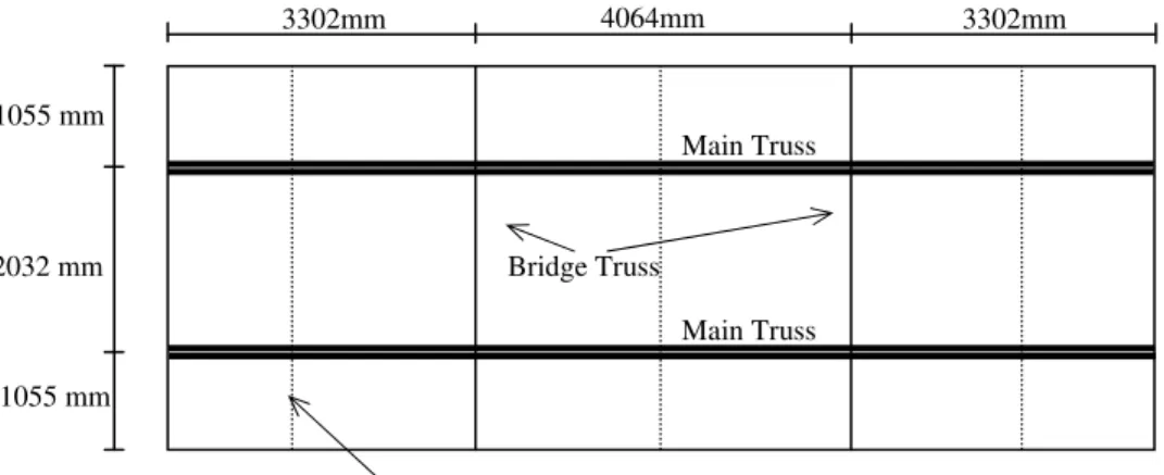
Two floor specimens were tested by the NIST at the ULC Toronto based on the ASTM E119 standard, one with restrained and one with unrestrained supports. The floor specimen configuration and dimensions are provided in Figure 1. The floor main truss, for specimen No. 1 with restrained support, the main truss for specimen No. 2 with unrestrained support and the details of the bridging truss are plotted in Figure 2.
4064mm
3302mm 3302mm
1055 mm
Main Truss
Figure 1. Configuration of the full-scale floor specimens.
2032 mm Bridge Truss
Main Truss 1055 mm
3×2×1/4“Angle welded at the top
Figure 3 identifies types of the steel sections for the top and bottom chords and the diagonal members of the truss specimens. A cross-section for the truss system, including the entire steel truss section and the concrete slab, is provided in Figure 4. Top and bottom chords and diagonal elements of the main and bridging trusses were coated by 19.05 mm thickness of the available SFRM (BLAZE-SHIELD DC/F by Isolatek International). Further details of the specimens can be found in the test report by Gross et al. (2005).
8K @ 997mm=7976mm
838mm 1854mm
10668mm 737 mm
a) Main truss specimen No. 1 with restrained supports.
b) Main truss specimen No. 2 with unrestrained supports.
c) Bridging truss.
Figure 2. Structural dimensions for a) main truss of specimen No. 1 and b) main truss for specimen No. 2 and c) bridging Truss.
Figure 3. Sections of steel elements for the main truss.
NUMERICAL MODELING Geometry and configuration
The floor specimens were modeled using the SAFIR software (Franssen, 2007), which is a program for analysis of structures for both structural and fire loads. Based on the support details shown in Figure 2-c, the bridging trusses have less stiffness than the main truss and would not be capable of transferring high shear force to the supports.
6×508mm=3048mm 597mm 597mm 4142mm 610 mm 127mm 127mm 146mm 146mm 8K @ 997mm=7976mm 1854mm 838mm 10668mm 737 mm 2L 2×1-1/2×0.25“ ø0.98“ 2L 2×1-1/2×0.25“ Web Splice ø0.92“ 3
Therefore, it was assumed that the main structural elements transferring the applied load to the test frame would be the main trusses. The concrete slab was assumed acting as a one-way slab in the direction of the main trusses, and compositely with the main trusses. These assumptions simplified the analysis to model only the main trusses with the concrete slab, and to ignore the bridging trusses. In addition, due to the symmetrical geometry only half of the floor specimen was modeled.
Figure 5 shows the model of the main truss for specimen No. 2, with unrestrained supports and the applied load. The geometry and the element sections for restrained specimen No.1 are similar to that of specimen No. 2. Except that for specimen No. 1 the truss’s right end support is restrained for horizontal displacement.
Figure 4. Cross-section of the floor system at the main truss location.
737 mm ø0.98“ Web Splice ø0.92“ 8K @ 997mm=7976mm 838mm 1854mm 10668mm 15075N/m 2L 2×1-1/2×0.25“
Figure 5. The main truss model for analysis of unstrained specimen No. 2. Material mechanical properties
Bottom chord angles of the truss were made of 2 L2×1-1/2×0.25“, as shown in Figure 4, with A572 steel and yield strength of fy= 425.5 MPa. Round bars with two different diameters, 0.92” and 0.98” were used as the diagonal elements for the truss. Figure 5 shows the web splice where the diagonal round bars changed from 0.98” to 0.92” section through the truss. The yield strength for bar 0.92” is fy= 402 MPa and for bar 0.98” is fy= 372 MPa. The concrete slab reinforcement of the floor consists of two layers of welded wire fabric 254mm × 102mm (10 in. by 4 in.), as shown in Figure 4. W4.2 wires with a diameter of 5.8mm (0.23”), a yield strength of 492 MPa and spacing of 254mm were placed in the longitudinal direction. W4.3 wires with a diameter of 5.9mm (0.234”), a yield strength of 498 MPa and spacing of 102 mm were located in the transverse direction. For the purpose of this study only longitudinal bars were included in the analysis, based on the assumption that the floor would act as a one-way slab structure. The above steel material properties were derived from the individual material property
tests reported by Gross et al. (2005), and applied to both specimens No. 1 and No. 2. The concrete slabs of the specimens were made of lightweight concrete. Mechanical properties of the concrete are provided in Table 1 for both specimens. The concrete compression strengths were taken from the test reports and the tensile strength of concrete were estimated according to equation (1) proposed by Vecchio in Wong and Vecchio (2002).
(1) where, is the tensile strength in MPa and is the concrete compression strength at 56 days in MPa.
Table 1. Mechanical properties of the floor lightweight concrete of specimens. Specimen Compressive Strength at 28 Days (MPa) Compressive Strength at 56 Days (MPa) Tensile Strength* (MPa) No.1 28.8 32.6 1.9 No.2 20.2 26.8 1.7
* estimated according to equation (1). Applied loads
The total uniform load for each floor specimen consists of two load cases: the uniform self weight construction load of 2298 N/m2 (48 psf) and an additional superimposed load of 4981 N/m2 (104 psf). Hence, the total applied uniform load on the floor is 7279 N/m2 (152psf). Since only one truss is modeled, due to the floors symmetrical geometry and loading, the linear uniform load on each truss is determined with multiplying the total uniform load by half of the floors’ width; uniform load (per unit length) = 7279N/m2 × 4.142 m / 2 =15075N/m, as shown in Figure 5.
Material thermal properties
In both floor specimens, the BLAZE-SHIELD DC/F was used as the SFRM in multiple coats with an average thickness of 0.75”, to protect elements of the main and bridging trusses. The test report indicated that no attempt was made to control overspray of material onto the deck of the test assemblies. Thermal properties of the SFRM were obtained at different temperatures based on the test repot by Carino et al. (2005). Thermal conductivity of the SFRM changes from 0.046 W/(m.K) at 25 oC to 0.53 W/(m.K) at 1200 oC. Specific heat for the SFRM starts with 826 J/(kg.K) at 25 oC and increases up to 1392 J/(kg.K) at 1200 oC. The density of the SFRM was considered variable for the analysis from 236 (kg/m3) at 25 oC to 432 (kg/m3) at 1200 oC, Carino et al. (2005).
For all steel elements of the truss, STEELEC3 material model of the SAFIR was used for both thermal and material properties. As for concrete, thermal properties were derived from the study results reported by Prasad and Baum (2005). Appendix A of the report provides these properties at different temperatures for the lightweight concrete. For concrete thermal conductivity the value is varied from 1.5 W/(m.K) at 25 oC to 1.00 W/(m.K) at 1200 oC and for specific heats it is from 880 J/(kg.K) at 25 oC to 1500 J/(kg.K) at 1200 oC. The lightweight concrete of the two specimens was designed for a density of 1600 kg/m3 (100 pcf) at ambient temperature, which is different from that of the concrete reported by Prasad and Baum (2005). Therefore, for this analysis, the
concrete density was reduced from 1600 kg/m3 at 20 oCto 1300 kg/m3 for 1200 oC. The reduction function was selected as those of the lightweight concrete used by Prasad and Baum (2005). Moisture content of concrete was obtained as 51 kg/m3, based on the reported 70% relative humidity, 0.23 chemically bound water, 237 kg (522lb) cement, and concrete water mix of 127 kg (281 lb).
Heat transfer analysis
Due to the round shape cross section, finite element (FE) meshes with triangle elements were generated to model cross sections of the diagonal elements of the truss assemblies. Figure 6 shows the FE mesh for these elements. Elements with a darker color represent the steel bars and elements with a lighter color form the SFRM materials. Using SAFIR, the heat transfer analysis was carried out for the web elements while they were exposed to standard fire, ASTM E 119. The results for the temperature distributions on the cross sections at the time = 3600 seconds are plotted in Figure 7. Figure 8 shows the comparison between analysis and test results for the temperature at the surface of the web elements at different time steps.
Figure 6. FE mesh for the double bar web elements, each with diameter of 0.98”.
Figure 7. Temperature distribution on sections of the web elements at time = 3600 sec.
Figure 8. Temperatures on the surface of the bar, web elements, for specimen No. 1.
0 200 400 600 800 1000 0 1200 2400 3600 4800 6000 7200 Te m p e ra tu re (d e g re e C) Time (sec) Test Analysis
In this figure, although the test results show a little lower temperature profile than that of the analysis, they are in close correlation. For the structural analysis, the
temperature results of the test were employed.
FE meshes with rectangular elements were assigned to both concrete and steel angles of the truss’s top and bottom chords of the assemblies. Based on the total cross-section area of the longitudinal steel reinforcement wires, two fiber elements on the top and two on the bottom of the slab cross-section were assigned as the slab steel
reinforcement, with each fiber away from the slab top and bottom edges in accordance with the cover concrete thicknesses. Since BEAM element, a fiber model, of the SAFIR package was used for modeling the cross sections, this lumping of reinforcement wires
into a limited number of fibers would have no effect on the results. Figure 9 shows the mesh generated for the top chord of the truss, concrete slab and steel angels. The steel deck was modeled for heat transfer analysis; however it was not included in the structural analysis as there would be no shear interaction between the deck and the concrete. The test observations for both assemblies indicated separation of the steel deck at the very early stage of the tests.
Figure 9. FE mesh for the top chord steel elements and the concrete slab.
In the initial thermal analysis, SFRM overspray was ignored, so the lower face of the floor was exposed directly to the assigned furnace temperature profile. First, the metal deck and the protected steel truss top chord angles were exposed to the furnace
temperatures measured in test and the analysis was carried out. In order to impose the exact test temperatures to the angles and the metal deck, large values were assigned to the convection coefficient on hot surfaces, convection coefficient on cold surfaces and
relative emissivity of the steel deck in the SAFIR input file. This would accelerate the heat transfer through the slab frontiers by convection and radiation.
In this initial analysis, the analytical results showed considerably higher temperatures, at the unexposed side of the slab, compared to that of the test data. This could be due to the separation of the metal deck from concrete, reported during the test. The gap between the concrete slab and the steel deck, which was not modeled in the initial analysis, could act as an additional insulation layer delaying the heat transfer to/through the slab. Therefore, the second analytical approach was to expose the slab directly to the measured concrete temperature profiles. However, no measurement was reported from the tests for temperatures on the bottom surface of the concrete. Therefore, an attempt was made to determine such temperatures for the bottom surface of the
concrete slab. Figure 10 illustrates the developed temperature histories for both
specimens. The concrete slabs were then exposed to the developed temperature histories for the heat transfer analysis.
The top chord steel angles of the specimens were subjected directly to the test temperatures, since the measurements were available. Figure 11 verifies that the temperatures on the top chord angles, measured during the test, are in exact agreement with those of the top chord mesh, determined from the analysis. The same verifications were obtained for the web elements and the bottom chords.
Figure 12 illustrates the results for temperatures at the unexposed surface of the floor assemblies. It indicates a consistent correlation between the test and the analytical results. The calculated temperature distribution in the concrete slab and top chord angles of the truss assembly No. 1 are illustrated in Figure 13.
Figure 10. Developed temperature histories for bottom surface of concrete. 0 200 400 600 800 1000 0 1200 2400 3600 4800 6000 7200 Te m p e ra tu re s (De g re e C) Time (Sec.) Specimen No. 1 Specimen No. 2
Specimen No. 1 Specimen No. 2
Figure 11. Temperatures on the top chord angles.
0 200 400 600 800 1000 0 1200 2400 3600 4800 6000 7200 Te m p er a tu res (D e g re e C) Time (Sec) p p Test Analysis 0 200 400 600 800 1000 0 1200 2400 3600 4800 6000 7200 Tem p er a tu res (De g re e C) Time (Sec) p p Test Analysis
Specimen No. 1 Specimen No. 2
Figure 12. Temperature results measured and determined on the unexposed surface of concrete. 0 200 400 600 800 1000 0 1200 2400 3600 4800 6000 7200 T e mp e rat u re s (Deg re e C) Time (Sec.) Test Analysis 0 200 400 600 800 1000 0 1200 2400 3600 4800 6000 7200 T em p er a tu res (D eg re e C) Time (Sec.) Test Analysis 260 233 206 178 151 124 97 70 43o C
Figure 13. Temperature distribution on the top chord cross-section of the floor assembly No.1 at time = 3600 sec.
Structural analysis
Structural analysis of the two truss assemblies were carried out using the same software package, SAFIR, by employing the defined material properties for each section and the calculated temperature distributions from the heat transfer analysis. In the
structural analysis, the metal deck of the floor was not simulated since, as mentioned earlier, there was no shear interaction between the slab and the steel deck. The
temperature distributions and material properties of the structural elements had minor differences in the two specimens. Hence, practically, the main difference between the two specimens was the restrained conditions of the truss end supports; that is being restrained for assembly No. 1 and unrestrained for assembly No. 2. Figure 14 shows the truss deflection, for specimen No. 1, generated by the SAFIR post-processor software, before and after fire exposure. Figures 15 and 16 compare analytical and experimental results for deflections in specimen No. 1 and No. 2, and indicate a consistent agreement between the analysis and the test results.
Figure 14. Truss specimen No. 1 with restrained ends before and after fire exposure.
Figure 15. Deflections histories for specimen No. 1: analysis and experimental results.
0 0.1 0.2 0.3 0 600 1200 1800 2400 3000 3600 4200 De fl e ct io n (m) Time (Sec.) Test Analysis
Figure 16. Deflections histories for specimen No. 2: analysis and experimental results.
0 0.1 0.2 0.3 0 600 1200 1800 2400 3000 3600 4200 De fl e ct io n (m ) Time (Sec.) Test Analysis
The floor assemblies were able to last significantly longer in the tests, compared to the analytical results shown in Figures 15 and 16. That was because the SAFIR software would fail to converge when the structure suffered certain level of damage; which was compression failure of the top fibers/layers of the slab for this analysis. However, during the tests, the floors can sustain higher levels of damage and
deformation. Observations from the test indicate significant spalling of the concrete in specimen No. 1, at both ends of the floor. This spalling occurred at about the same time as the convergence failure obtained from the analysis, preceded by sharp acceleration of deformations, as shown in Figure 15.
Figure 17 shows the total axial load in element #10 of the truss in Figure 14, for both the restrained specimen No. 1, and the unrestrained specimen No. 2. These
analytical results indicate a difference of about 15 times between the restrained and unrestrained specimen axial loads, which show the considerable effects of supports restraint conditions on the structural response. The results convey the fact that the significant spalling observed during the test for specimen No. 1 would be the result of compression failure of the top fibers/layers of the concrete slab.
Figure 17. Axial load in element 10 of both restrained, specimen No. 1, and unrestrained specimen No. 2, assemblies (see Figure 14 for elements number).
0 500 1000 1500 2000 2500 0 600 1200 1800 2400 3000 3600 Ax ia l Lo a d (k N ) Time (sec) Specimen No. 1 Specimen No.2
In addition to the deformation and load response, strain and stress results for the concrete were investigated. Figure 18 and Figure 19 provide stress and strain distributions on the cross section of the concrete slab for element #10 of the restrained truss, specimen No. 1, at the time of failure. Figure 19 provides mechanical strains on the section, which is determined by SAFIR by subtraction of the thermal expansion strain from the total strain. Both results indicate that at this time step, the extreme top fibers of the concrete, cover concrete, fail in compression when concrete compression stress reaches 32 MPa or concrete compression strain achieved 0.002.
-40 -30 -20 10 0.0 10 20 30 40 MPa
Figure 18. Stress distribution on the top chord of specimen No. 1 for element #10 of the truss at the time of concrete failure.
-0.002 -0.0015 -0.0015 -0.0005 0.0 0.0005 0.001 0.0015 0.002
Figure 19. Mechanical strain distribution on the top chord of specimen No. 1 for element #10 of the truss at the time of concrete failure.
To study the stress and strain development, stress and strain distributions of the concrete slab were obtained for the vertical center line section of the slab at different time steps. Figures 20 through 23 illustrate the stresses and curvatures for both specimens. The analytical results clearly indicate that the stress and strain are considerably higher in the case of restrained specimen compared to that of the unrestrained assembly. It can also
be pointed out that the section experienced significantly larger curvature at the time of failure compared to that of the ambient temperature, which could be the result of large thermal expansion of the truss.
0 25 50 75 100 Co n c re te Fl oo r Se c ti o n He ig h t (mm) Time (min) = 1 10 20 30 40 50 53‐F C.L. ‐ 32MPa
Figure 20. Stress profile at the vertical center line of the concrete slab section for specimen No. 1 at different time steps.
0 25 50 75 100 Co n c re te F loor Se c ti o n He ig h t (m m) Time (min) = 1 10 20 30 40 50 53‐F C.L. ‐ 0.002
Figure 21. Mechanical Strain profile at the vertical center line of the concrete slab section for specimen No. 1 at different time steps.
Figure 22. Stress profile at the vertical center line of the concrete slab section for specimen No. 2 at different time steps.
0 25 50 75 100 Co n c re te Fl oor Se c ti o n He ig h t (mm) Time (min) = 1 10 20 30 40 50 53 C.L. ‐8MPa 0 25 50 75 100 Co n cret e Fl oor Se ct io n He ig h t (mm) Time (min) = 1 10 20 30 40 50 53 C.L. ‐0.0006
Figure 23. Mechanical Strain profile at the vertical center line of the concrete slab section for specimen No. 2 at different time steps.
Results from this numerical study and the two test assemblies indicated that overall performance of unrestrained floor specimen was better than the restrained
specimen. Future comparative tests of restrained vs. unrestrained floor assemblies would be suggested to confirm if unrestrained floors perform better in other comparative tests.
In this study, no damage to the fireproofing materials of the truss, due to the initial impact and jet fuel explosion, is considered. In the 9/11 fire, the WTC towers’ floors were exposed to a hydrocarbon fire load, however, in this investigation the composite floors were exposed to a standard fire, ASTM E119. In addition, the horizontal support
12
restraint condition for the test assembly No. 1 was only in compression. The floor specimen was free to displace in tension. However, in practice such restraint conditions would be imposed both in compression and tension.
Future studies would be recommended to investigate the above mentioned deficiencies in different scenarios.
CONCLUSIONS
A numerical study was carried out to investigate failure mechanism of the World Trade Center composite floors. The results from the analysis and the comparisons with the test results of the two full-scale floor assemblies, suggested the following conclusions:
Separation of the metal deck from the concrete slab during the fire would have decreased the heat transfer to the concrete slab.
The significant spalling of concrete and large deformation of specimen No. 1 at about 50 minutes would have been due to the thermal expansion of the truss resulting in compression failure of the top fibers of the concrete slab.
The axial load in the restrained truss assembly was significantly (about 15 times) higher than that of the unrestrained specimen.
ACKNOWLEDGMENT
Acknowledgements are extended to Mr. Joe Hum from NRC Fire Research Program for developing a post-processor software to simulate the stress and strain diagrams and his contribution in this study.
REFERENCES
Carino, N.J., Starnes, M.A., Gross, J.L., Yang, J.C., Kukuck, S.R., Prasad, K.R., Bukowski, R.W. (2005). “Passive Fire Protection”, Federal Building and Fire Safety Investigation of the World Trade Center Disaster, NIST NCSTAR 1-6A, National Institute of Standards and Technology, 326 pp.
Franssen, J.M. (2007). User’s Manual for SAFIR 2007a Computer Program For Analysis of Structures Subjected to Fire, University of Liege, Belgium, 79 pp.
Gross, J., Hervey, F., Izydorek, M., Mammoser, J., Treadway, J. (2005). “Fire Resistance Tests of Floor Truss Systems”, Federal Building and Fire Safety Investigation of the World Trade Center Disaster, NIST NCSTAR 1-6B, National Institute of Standards and Technology, 202 pp.
NIST (2005). “Final Report of the National Construction Safety Team on the Collapses of the World Trade Center Tower “, Reports of the Federal Building and Fire Investigation of the World Trade Center Disaster, NIST NCSTAR 1, , National Institute of Standards and Technology, 298 pp.
Prasad, K., Baum H., (2005). “Fire Structure Interface and Thermal Response of the World Trade Center Towers”, Federal Building and Fire Safety Investigation of the World Trade Center Disaster, NIST NCSTAR 1-5G, National Institute of Standards and Technology, 338 pp.
Wong, PS, Vecchio, FJ. (2002). “Vector2 & Formwork user’s manual”, Department of Civil Engineering, University of Toronto; 214 pp.