Publisher’s version / Version de l'éditeur:
Canadian Journal of Civil Engineering, 37, 4, pp. 511-521, 2010-05-01
READ THESE TERMS AND CONDITIONS CAREFULLY BEFORE USING THIS WEBSITE. https://nrc-publications.canada.ca/eng/copyright
Vous avez des questions? Nous pouvons vous aider. Pour communiquer directement avec un auteur, consultez la première page de la revue dans laquelle son article a été publié afin de trouver ses coordonnées. Si vous n’arrivez pas à les repérer, communiquez avec nous à PublicationsArchive-ArchivesPublications@nrc-cnrc.gc.ca.
Questions? Contact the NRC Publications Archive team at
PublicationsArchive-ArchivesPublications@nrc-cnrc.gc.ca. If you wish to email the authors directly, please see the first page of the publication for their contact information.
NRC Publications Archive
Archives des publications du CNRC
This publication could be one of several versions: author’s original, accepted manuscript or the publisher’s version. / La version de cette publication peut être l’une des suivantes : la version prépublication de l’auteur, la version acceptée du manuscrit ou la version de l’éditeur.
For the publisher’s version, please access the DOI link below./ Pour consulter la version de l’éditeur, utilisez le lien DOI ci-dessous.
https://doi.org/10.1139/L09-169
Access and use of this website and the material on it are subject to the Terms and Conditions set forth at
Innovative design approach of precast-prestressed girder bridges using ultra high performance concrete
Almansour, H.; Lounis, Z.
https://publications-cnrc.canada.ca/fra/droits
L’accès à ce site Web et l’utilisation de son contenu sont assujettis aux conditions présentées dans le site LISEZ CES CONDITIONS ATTENTIVEMENT AVANT D’UTILISER CE SITE WEB.
NRC Publications Record / Notice d'Archives des publications de CNRC:
https://nrc-publications.canada.ca/eng/view/object/?id=1932fd24-b57b-45b0-bc4e-530002a9624b https://publications-cnrc.canada.ca/fra/voir/objet/?id=1932fd24-b57b-45b0-bc4e-530002a9624b
http://www.nrc-cnrc.gc.ca/irc
I nnova t ive de sign a pproa c h of pre c a st -pre st re sse d girde r bridge s using ult ra high pe rform a nc e c onc re t e
N R C C - 5 1 1 2 8
A l m a n s o u r , H . ; L o u n i s , Z .
M a y 2 0 1 0
A version of this document is published in / Une version de ce document se trouve dans:
Canadian Journal of Civil Engineering, 37, (4), pp. 511-521, May 01, 2010,
DOI: 10.1139/L09-169
The material in this document is covered by the provisions of the Copyright Act, by Canadian laws, policies, regulations and international agreements. Such provisions serve to identify the information source and, in specific instances, to prohibit reproduction of materials without written permission. For more information visit http://laws.justice.gc.ca/en/showtdm/cs/C-42
Les renseignements dans ce document sont protégés par la Loi sur le droit d'auteur, par les lois, les politiques et les règlements du Canada et des accords internationaux. Ces dispositions permettent d'identifier la source de l'information et, dans certains cas, d'interdire la copie de documents sans permission écrite. Pour obtenir de plus amples renseignements : http://lois.justice.gc.ca/fr/showtdm/cs/C-42
1
Innovative Design Approach of Precast-Prestressed Girder Bridges
Using Ultra High Performance Concrete
H. Almansour1, Z. Lounis2
1 Research Officer, National Research Council Canada, 1200 Montreal Road, Ottawa, ON, K1N 6N5.
2 Senior Research Officer and Group Leader, National Research Council Canada, 1200 Montreal Road, Ottawa, ON, K1N 6N5.
2
Abstract: The construction of new bridges and the renewal of aging highway bridge network using ultra high performance concrete can lead to the construction of long life bridges that will require minimum maintenance resulting in low life cycle costs. Ultra high performance concrete (UHPC) is a newly developed concrete material that provides very high strength and very low permeability. UHPC could enable major improvements over conventional high performance concrete (HPC) bridges in terms of structural efficiency, durability and cost-effectiveness over the long term. A simplified design approach of concrete slab on UHPC girders bridge using the Canadian Highway Bridge Design Code and the current recommendations for UHPC design is proposed. An illustrative example demonstrates that the use of UHPC in precast/prestressed concrete girders yields a more efficient design of the superstructure where considerable reduction in the number of girders and girder size when compared to conventional HPC girders bridge with the same span length. Hence, UHPC results in a significant reduction in concrete volume and then weight of the superstructure, which in turn leads to significant reduction in the dead load on the substructure, especially for the case of aging bridges, thus improving their performance.
Key words: flexural design approach, precast/prestressed bridge girder, performance based design, ultra-high performance concrete
3
Introduction
The recent developments in high and ultra high performance concrete and fast precast concrete construction technologies for highway bridges should be used to develop the new generation of high performance bridge systems that will satisfy the requirements of safety, serviceability durability and economy. The development of such high performance bridge systems is becoming an urgent need to address the challenges facing Canada’s as well as North America’s aging and deteriorating concrete and steel bridges that are approaching the end of their design life.
The construction of new bridges and the renewal of existing highway bridge network using ultra high performance concrete can lead to the construction of long life bridges that will require minimum maintenance resulting in low life cycle costs. Ultra high performance concrete (UHPC) is a newly developed concrete material that provides very high strength and very low permeability. UHPC could enable major improvements over conventional high performance concrete (HPC) bridges in terms of structural efficiency, durability and cost-effectiveness over the long term.
Slab on precast girders is one the most common forms of structural systems used for the construction of highway bridges in North America due to their good long term performance and cost effectiveness (Lounis et al. 1993, 1997). Over the past century and throughout a progressive improvement process, the precast/prestressed practice and industry standardized the girder sections for use with conventional and high performance concrete. The use of standard precast/prestressed girder sections is a popular and cost-effective choice for the construction and replacement of short and medium span bridges,
4 as well as the construction of long span bridges using segmental construction and splicing girders by post-tensioning (Lounis et al. 1997). Throughout the last four decades there was a considerable growth in the use of high strength/high performance concrete (HSC/HPC) in highway bridges. With a compressive strength up to 85 MPa and tensile strength up to 3 MPa, the benefits of using HPC/HSC to extend the span length capability or reduce the weight of slab-on-precast girder bridge systems reach a limit at about 50 MPa, beyond which there are only marginal improvements, as the governing design criterion is the condition of no cracking at service (Lounis et al. 1993, 1997). The development of UHPC represents a major innovation in the concrete industry that can help overcome some of the shortcomings of HPC/HSC such as strengths that are at least twice the compressive and tensile strengths of HSC/HPC and permeability to chlorides order of magnitude lower than that of HPC/HSC. The use of UHPC in slab on girder bridges could lead to considerable reduction in the number of girders and girder size, and could enable the construction of long life bridges.
As of now, a limited number of bridges have been designed and built using UHPC in Europe (Hajar et al. 2004) and in the United States (Meda et al. 2003) and opened to traffic recently. There is a need for comprehensive structural evaluation of the behaviour of such bridge systems, as well as the development of design methodologies for this type of construction is still required. The first UHPC highway bridge (Hajar et al. 2004) was designed and constructed in France and opened to traffic in 2001 with two simply
supported spans of 22 m each. At the same time, another UHPC bridge (Meda et al. 2003) was constructed in Italy with a span of 11.8 m. More recently, a 33.8 m span UHPC bridge was designed and constructed in Iowa and opened to traffic in late 2005
5 (Bierwagen et al. 2005). The only available design guidelines for UHPC structures are the French Interim Recommendations (AFG-IR 2002), which provide modifications to the existing French design standards for reinforced and prestressed concrete structures. The recent draft recommendation of the Japan Society of Civil Engineers for the design and construction of UHPC structures (JSCE No 9 2006) proposed some modifications compared to the earlier French recommendations.
Both recommendations are not developed specifically for highway bridge structures and not necessarily compatible with the Canadian bridge design code safety requirements and traffic load models. Hence there is an urgent need to develop a procedure for the design of UHPC bridges according to the Canadian Highway Bridge Design Code (CAN/CSA-S6-06 2006 or CHBDC 2006) and using the available standard Canadian Prestressed Concrete Institute (CPCI Design Manual 1996) precast/prestressed I-girder sections. An iterative analysis and design procedure was proposed for concrete slab on
precast/prestressed UHPC girders (Almansour and Lounis 2007) and a preliminary evaluation of the structural performance of this type of bridge and comparison to typical HPC bridges is carried out (Almansour and Lounis 2008).
The objectives of this paper are twofold; (i) propose a simplified design approach for slab on ultra high performance concrete UHPC girder bridges, and (ii) compare its structural efficiency to conventional concrete slab on HPC girder bridges.
6
Mechanical Properties of Ultra High Performance Concrete
Based on advances in nano-technology, ultra high performance concrete (UHPC) was developed to achieve very high durability through ultra-high dense packing by means of refined mix-design involving minimum water cement ratio (w/cm < 0.2), high percentages of cement and silica-fume, fine sand without using aggregates (Ulm et al. 2008). UHPC is reinforced at the micro level by means of uniformly distributed short fibres with a percentage that can vary from 2 to 12 % (by volume of concrete). The fibre length is either constant or variable ranging from 1 to 20 mm. Depending on the fibres length and volumetric proportion, there are three major types of UHPC: (i) UHPC with high proportions of short fibres, introduced in Denmark in 1987 (Rossi 2008); (ii) UHPC with intermediate proportion of long fibres, introduced in France 1995; and (iii) UHPC with very high proportion of fibres of various lengths, introduced in France 2000 (Parant et al. 2007; Rossi 2008).
Fibre reinforcement of UHPC, heat treatment and materials’ high homogeneity due to the use of very fine aggregate only contribute to eliminate the initiation of extensive early age cracks that are the major disadvantage of high strength/ high performance concrete. The superior macro-level mechanical properties of UHPC, such as very high compressive and tensile strengths and high modulus of elasticity, high ductility, and high fatigue strength, could enable the development of lighter bridge superstructures that would reduce number of girders and/or support longer spans than conventional HPC/HSC. The compressive strength of UHPC can vary in a very wide range from 120 to 400 MPa, its direct tensile strength can vary from 8 to 30 MPa, and its modulus of elasticity is in the range of 60 – 100 GPa (Acker et al. 2004; Buitelaar et al. 2004). Typical stress-strain
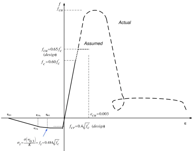
7 relationships and typical tensile (bending) stress versus displacement of ultra high performance fibre reinforced concrete are compared to those of a typical high performance concrete in Figure 1-a and Figure 1-b, respectively. Figure 1-a also shows the conservative elasto-plastic approximation of compressive behaviour of UHPC that is assumed in design.
The uniform distribution of the fibres in the UHPC matrix is hard to achieve and different fibre orientations are observed in practice due to the casting process, element size,
geometry, thickness, and distribution of non-prestressed and prestressed reinforcement throughout the element length (Kim et al. 2008; Schnell et al. 2008; Pansuk et al. 2008). Since the fibre alignment could result in local or overall anisotropy in UHPC, the
mechanical properties are affected locally or throughout the entire structural element depending on the affected region, location and size. The material properties could be improved in some directions and lowered in other directions, which could result in weak regions that would develop cracks under tensile stresses or fail under compressive stresses well below the anticipated levels. Furthermore, the anistropic behaviour adds more complications in the structural analysis of UHPC system; nevertheless in some situations the anisotropy could improve the overall performance of the structural element if it properly is accounted for in the structural design. However, and to simplify the analysis and design procedure and given the lack of comprehensive experimental data on UHPC behaviour, it is generally recommended to use a reduction factor applied to the homogenized properties from the standard material tests (AFG-IR 2002; JSCE No 9 2006).
8 General design recommendations for the use of UHPC in reinforced and prestressed concrete structures have been first developed in France (AFG-IR 2002), followed by the Japanese recommendations (JSCE No 9 2006) and recently a new design recommendations for UHPC structures was released in Germany (2008). FIB is also developing a first set of European design rules for UHPC. However, no recommendations have been developed yet in North America. On the other hand, no specified recommendations for the use of UHPC in bridge design have been developed in Europe or North America.
Design Approach for Prestressed UHPC Girders
GeneralMost existing structural concrete design codes and standards (including the bridge design codes)limit the concrete compressive strength to a maximum of 80 to 85 MPa. The use of UHPC with its very high compressive and flexural strengths is investigated in the present study with reference as much as possible to the French and Japanese UHPC design recommendations (AFG-IR 2002) and (JSCE No 9 2006), Canadian highway bridge design code CHBDC 2006, and use of engineering judgment. The material reduction factor at ultimate limit state (ULS) for UHPC must be calibrated based on lifetime target reliability index of CHBDC 2006. A rigorous reliability-based analysis is needed to determine the appropriate reduction factor for UHPC to ensure lifetime reliability indices that are consistent with the requirements of the bridge design code for flexural and shear design. However, given the lack of data on strength variability and performance to failure
of UHPC beams, the material reduction factors are assumed conservatively in this study to be the lowest of the values given by the French recommendations (AFG-IR 2002) and the CHBDC 2006. The derivation of more appropriate factors for UHPC is being investigated by Lounis and Almansour.
Serviceability Limit States
Given the lack of data on the performance of UHPC girders in the field, the bridge will be designed for no crack at transfer and at serviceability limit states (SLS), by keeping the tensile stresses below the cracking limit for both cases i.e. assuming fully prestressed girders. Compressive strength of heat-treated UHPC gains almost 95% of its full strength within the first few days and way before transfer (AFG-IR Cl 1.2 2002) and (JSCE No 9 Cl 3.2 2006). A conservative limit on the compression strength at transfer of 85% of the 28 day strength is assumed in the present paper, or (i.e. ). The allowable compressive stress at transfer is taken conservatively as (CHBDC Cl 8.8.4.6 2006) and (AFG-IR Cl 6.1,12 2002). Using both CHBDC (2006) and AFG-IR (2002), the allowable tensile strength at transfer is assumed equal to:
' ' 0.85 c ci f f = ' 6 . 0 fci = ci f cri f [1] 0.4 ' ci cri f f =
The allowable compressive stress at SLS is equal to 60% of the UHPC compressive strength (Figure 2), i.e.,
c
f
[2] f 0.60fc'
c =
The maximum tensile strength is equal to the first crack strength
( )
fcr . Linear elastic analysis is to be carried out at SLS with the assumption that plane sections remain plain and stresses are linearly proportional to strains. The static deflection of the bridge under gravity loads and the maximum deflection for superstructure vibration should satisfy the bridge design code limits.Although the CHBDC (2006) and AFG-IR (2002) allow tensile stresses that exceed the cracking limit at SLS, in this paper the tensile stress is limited to the cracking limit. Hence, the stiffness calculations at SLS involve the entire cross sectional area. Using the French recommendations AFGC, Cl 6.1,11 (2002), the allowable tensile strength of UHPC at serviceability limit state is given by:
[3a]
( )
K w ft 3 . 0 σ =where ft is the allowable tensile stress, σ
( )
w0.3 is the tensile stress corresponding to acrack width of 0.3 mm (see Figure 2) and represents the basis for fibre tensile strength, and 1/K is an orientation coefficient to account for the actual variability in fibre orientation due to placement. K is equal to 1.25 for all loading other than local effects (which is used in this paper), and equal to 1.75 for local load effects. Expressing the allowable tensile strength in terms of '
c
f to be consistent with the Canadian bridge design code and substituting in equation (3a), the allowable tensile strength at serviceability limit state is equal to '
484 . fc
0 and will be conservatively assumed equal
to:
[3b] ' 4 . 0 c t f f =
This value will be the design cracking limit at SLS, which is much lower than the direct tension test result of UHPC (Figure 2).
Proposed Approach for Flexural Design of UHPC Girders at Ultimate Limit State
At the Ultimate Limit State (ULS), a bi-linear stress-strain relationship is assumed (AFG-IR Cl. 6.3,313, 2002) as shown in Figure 1(a) which includes: (i) a first line from zero stress and zero strain up to a strength of
( )
fcu and a strain of(
fcu /Euhpc)
003
; and (ii) a second line that is horizontal up to the ultimate strain of εcu =0. , (εcu =0.0035in the Japanese recommendations). The ultimate strength is given as (AFG-IR 2002) and adapting to CHBDC (2006) yields: ) (fcu [4a] θ ϕc cj cu f f =0.85
where: is the cylinder compressive strength at age j, which is taken in the present study equal to 28 days;
cj f
θ: is a factor related to the probability of the load application period or rate of loading: θ =1.0 for loads with application period equal or exceeds 24 hours, θ =0.9 for loads applied over a period between 1 hour and 24 hours, and θ =0.85 for the loads with period of application of less than one hour.
c
φ : is a coefficient that takes into account the variability of UHPC resistance as well as localized effects. UHPC resistance factor in the present paper is derived from the French recommendation as φc =1/γb, which is equal to φc =0.75 for load combinations 1 and 2 11
and 95φc =0. for exceptional combinations, e.g. seismic load (AFG-IR Cl 6.2.1, 2002). The Japanese recommendations suggest φc =0.75for all loading cases, however, with further availability of material test data, increase of φc value is possible. It is important to mention here that while undergoing heat curing, there is significant decrease in shrinkage and creep of UHPC, while there is significant decrease in permeability. Compared to the conventional concrete, UHPC would be less vulnerable to the effects of time-dependent changes and sustained loading.
Substituting the factors values and using the symbol for the compressive strength, the ultimate compressive strength of UHPC varies from to . Equation (4a) conservatively yields: ' c f ' 65 . 0 fc ' 77 . 0 fc [4b] '. c f 65 . 0 cu f =
For a conservative estimation of flexural strength of pretensioned UHPC element, the effect of tension stiffening of the fiber reinforced UHPC is ignored in this paper. At ultimate limit state (ULS), the factored bending moment and shear force should be less or equal to the factored flexural strength and shear strength, respectively. A ductile failure at ULS has to be ensured so that the tensile stresses in the prestressing steel are kept below the factored ultimate tensile strength (i.e. 0.95 fpu) by ensuring that the prestressing steel tensile strain at failure is beyond the yield strain. In CHBDC, this is ensured by checking that the amount of flexural reinforcement provided shall be such that the factored flexural resistance is developed with relative neutral axial depth (c/d) is less than 0.5.
Assume that the slab acts compositely with the girders through a composite section formed from concrete slab of thickness and UHPC prestressed girder of depth , ( Figure 3a and b). The equivalent slab width is equal to the effective slab width
(according to CHBDC 2006) divided by the modulus of elasticity ratio
slab
t Hs
(
Egirder /Eslab)
c =
. Assuming a linear strain distribution over the composite section depth and a bilinear stress distribution for UHPC under compression, while the tensile resistance of UHPC under tension is ignored. From Figure 3, equilibrium conditions dictates that C ,
where is the sum of all the internal compressive force components on the
cross section, and is the tensile force in the prestressing steel at ULS.
p T
∑
=
i c cC
iC
TpThree major cases can be identified as follows:
Case A: Neutral axis in the girder web - c ≥hft +tslab
As shown in Figure 3(a), the compressive stress varies linearly from zero to (Eq. 3b), then the distance from the neutral axis to the first fiber under stress equal to
is cu cgu f f = cgu f c r cu bc fo =ε × ε
and the strain at this fiber is
cg cgu bu E f =
ε . The depth of the fully stressed compressive zone, or the zone under constant compressive stress of
( )
fcgu is given by:[5] r c cu bc cu fu ⎟⎟× ⎠ ⎞ ⎜⎜ ⎝ ⎛ − = ε ε ε
Comparing rfuwith tslabandtslab +hft, three secondary cases can be considered as follows:
Case A-1: Depth of fully stressed zone - rfu ≥tslab +hft
Both the slab and the top flange in this case are under compressive stresses equal to . A portion of the compressive zone of the web is under a stress of and the rest is under a linearly varying stress from to zero at the neutral axis. The compressive force component in the slab is equal to:
cgu f cgu f cgu f
[6a] Cc1=befcgutslab
and the resulting compressive force component of the top flange is given by:
[6b] Cc2=bftfcguhft
The compressive force component in the web is given by:
[6c]
{
(
)
}
⎥ ⎥ ⎦ ⎤ ⎢ ⎢ ⎣ ⎡ ⎟⎟ ⎠ ⎞ ⎜⎜ ⎝ ⎛ + + − = 2 3 cgu fo cgu ft slab fu w c f r f h t r b CCase A-2: Depth of fully stressed zone: tslab ≤rfu ≤tslab +hft
In this case, the slab is under maximum compressive stress , while only a portion of the top flange with area equal to
cgu f
(
)
[
rfu −tslab ×bft]
is under the maximum compressivestress, fcgu, and the rest of the top flange is under stress that varies linearly from fcgu to
(
)
fo cw fo cgu r h r × f f = − , where hcw =tslab +hft −rfu 3 c C. For simplicity in calculating the
compressive resistance, the force acting on a small strip of area equal to is removed from and added to . The compressive zone of the web and the added
w cw b h × 2 c C 14
strip of the flange are under linearly varying stress from to zero at the neutral axis. The compressive force component of the slab is equal to:
cgu f
[7a] Cc1=befcgutslab
The compressive force resulting from the integration of the compressive stress over the flange (minus the deducted strip) is equal to:
[7b]
(
) (
)
⎟⎟ ⎠ ⎞ ⎜⎜ ⎝ ⎛ + − + − = 2 2 cgu cw w ft slab fu cgu ft c f f h b b t r f b Cand the web component (plus the added strip) is equal to:
[7c]
(
)
⎟⎟ ⎠ ⎞ ⎜⎜ ⎝ ⎛ − = 2 3 cgu fu w c f r c b CCase A-3: Depth of fully stressed zone: rfu ≤ tslab
In this case, only part of the slab is under stress . The depth of the partially stressed slab zone is . The compressive stress of girder’s top fiber is
cgu f fu slab cw t r h 1= −
(
)
fo cw fo r h 1 − cgu r ff1= × and the distance from the neutral axis to the bottom fiber of the
compressive girder flange ishcw2=rfo+hcw1−hft and the compressive stress at the girder top-flange to web connection is
[8a] fo cw cgu r h f f 2 2 = × 15
The compressive force component of the fully and partially stressed zones of the slab is equal to: [8b] ⎟⎟ ⎠ ⎞ ⎜⎜ ⎝ ⎛ + + = 2 1 1 1 f f h b r f b Cc ecgu fu e cw cgu
the compressive force component of the compressive girder flange is equal to:
[8c] ⎟ ⎠ ⎞ ⎜ ⎝ ⎛ + = 2 2 1 2 f f h b Cc ft ft
The compressive force component of the web is equal to:
[8d]
(
)
⎟ ⎠ ⎞ ⎜ ⎝ ⎛ − − = 2 2 3 f h t c b Cc w slab ftCase B: Neutral axis in top flange of girder, i.e.tslab ≤c ≤hft +tslab, as shown in Figure 3b [9a] r c cu bc fo = ε × ε [9b] cg cgu bu E f = ε [9c] r c cu bc cu fu ⎟⎟× ⎠ ⎞ ⎜⎜ ⎝ ⎛ − = ε ε ε
Two secondary cases can be derived as follows:
Case B-1: tslab ≤rfu ≤tslab +hft
The slab is under stress equal to . The top flange is divided into two zones: a compressive zone under a stress varying from to zero and a possible fully stressed portion, and a tensile stress zone over the remaining top flange depth, i.e.
(
)
cgu f cgu f c h tslab + ft − . The compressive component from integrating the stresses in the slab is given by:
[10a] Cc1=befcgutslab
The compressive force component in the flange is given by:
[10 b]
(
)
(
)
⎟⎟ ⎠ ⎞ ⎜⎜ ⎝ ⎛ − + − = 2 2 cgu fu ft cgu slab fu ft c f r c b f t r b C Case B-2: rfu <tslabA portion or the slab is under stress equal to , while the other part is under a linearly
varying stress from to
cgu f cgu f
(
)
fo cw fo cgu r h r ff = × − at the lower fiber of the slab, where
. The top flanges’ compressive stress zone is under stress varying from
fu slab cw t r
h = − f
to zero. The compressive force component in the slab is giving by:
[11 a]
(
)
⎟⎟ ⎠ ⎞ ⎜⎜ ⎝ ⎛ + − + = 2 1 f f r t b r f bCc ecgu fu e slab fu cgu
The compressive force component in the flange is:
[11 b]
(
)
⎟ ⎠ ⎞ ⎜ ⎝ ⎛ − = 2 2 f t c b Cc ft slabCase C: Neutral axis is located in the slab, i.e.
c
≤
t
slabThen the slab is divided into two zones, a compressive stress zone under stress vary from to zero and a tensile stress zone, while the entire girder will be under tensile stress. The compressive force component of the fully stressed zone is givin by:
cgu f
[12 a] Cc1=befcgurfu
while the compressive force component of the linearly varying stress zone is given by:
[12 b] ⎟⎟ ⎠ ⎞ ⎜⎜ ⎝ ⎛ = 2 2 cgu fo e c f r b C
For any of the cases A, B or C shown above the resultant compressive force is given by:
[13]
∑
= = m i ci c C C 1where, m is the number of compressive force components according to the suitable case given above. The location of the resultant from the top compression fiber of the composite section is given by:
c C [14]
∑
∑
= = × = m i ci ci m i ci C C a C a 1 1 18where, is the location of force component from the top compression fiber of the composite section. ci a Cci 19
)
The centre of gravity of the prestressing steel is then calculated for critical flexural sections, and through a trial-and-error process, the equilibrium of the internal forces is satisfied
(
Cc =T . Hence, the flexural resistance of UHPC is giving by:[15] Mr =Cc
(
dp −ac)
p
d
where, is the depth of the prestressed steel from the top compression fiber.
Two limits for the moment resistance are to be checked, which are: (i) for minimum reinforcement, where is the section flexural capacity at first crack; and (ii)
for maximum reinforcement to ensure ductile failure (CHBDC 2006).
cr r M M ≥1.2 cr M 5 . 0 /dp < c
Shear Design of UHPC Girders at Ultimate Limit State
The ultimate shear strength Vu of ultra high performance concrete girders consists of three components: (i) UHPC contribution, Vc; (ii) shear reinforcement contribution, Vs; and (iii) prestressing reinforcement contribution through the effective prestressing force component in the direction of applied shear, Vp. UHPC is treated as a composite material that combines the contribution of the cementitious matrix and fiber reinforcement. Hence, meeting the terms of the conventional shear resistance requires that all the strength
parameters of the fibers and the matrix should be integrated into one factor that represents the overall shear strength of the material. Therefore, it is essential to simulate the load carrying mechanism in one expression rather than dividing it into components, which are
not representing the real UHPC shear failure mechanism. After UHPC cracks, the randomly distributed fibers provide most of the shear capacity. However, there is a lack of knowledge and data at the present time on how to include the effect of the fiber reinforcement into such an expression of shear strength.
A simplified approach is used to estimate the shear strength of ultra high performance fiber reinforced concrete UHPC (with at least 2% volumetric fiber content), which is based on the proposed models of AFGC-IR (2002) and JSCE No 9 (2006).
The shear resistance of UHPC or the shear load carrying mechanism is hypothetically divided it into three components: (i) first component represents the composite action of the matrix and the fiber; and (ii) the second component represents the shear capacity provided by the average fiber tensile resistance (before fiber pull out) acting along the diagonal cracks; and (iii) the third component is shear capacity provided by stirrups and prestressing. The overall shear resistance is given by:
[16] Vr =
(
Vc +Vf)
+Vp +VsThe limited available experimental results (FHWA-HRT-06-115, 2006) are in agreement with AFG-IR (2002) estimation; however, more research is needed to assess the shear resistance of UHPC.
Following the simplified approach of AFG-IR
(
2002)
, the shear strength of UHPC composite (concrete matix and fibers) is divided into two components (AFG-IR Cl 7.3,21, 2002) and adapting to the Canadian Bridge Code: (i) the concrete contribution,Vc:[17] V fcjb z E c c 0 24 . 0 γ φ =
The coefficient γE characterizes the current uncertainty regarding the possibility of extrapolating to UHPC the design equations established for HPC for which f’c≤ 85 MPa.γE is taken equal to 1.15 for CHBDC ultimate limit states 1 and 2; fcj is the concrete compressive strength at age j days (or 28 days in the present paper), b0 and z are the effective web shear width and depth, respectively. Then the concrete contribution to shear strength is Vc fc b0z
'
16 .
0 ⋅
= , and the fiber contribution Vf:
[18] u bf p f S V β γ σ tan =
where σ is the residual tensile strength: p
[19] =
∫
lim 0 lim ) ( 1 1 w p w dw w K σ σwhere, wlim =max
(
wu,0.3mm)
;wu =lcε
u,ε
uis the ultimate strain of 0.003, lc h3 2
= , h is the total height of the section;σ(w)is the experimental characteristic post-cracking stress corresponding to a crack width w; is the ultimate crack width; S is the area of the fiber effect, or ; d is the depth of the prestressing steel from the top compression fiber; K is the fiber orientation coefficient for general effect (K = 1.25);
u w d b S=0.9 0 S=b0z 3 . 1 = bf
γ and βu is the angle of the compression struts as measured from the horizontal and lower bounded to 30º (AFG-IR Cl 7.3,3 2002).
The shear reinforcement contribution, , is calculated in the same way as for HPC girders following CHBDC (2006). It is important to mention here that the French Recommendations (AFG-IR 2002) allow the use of shear reinforcement with UHPC structural elements in a similar manner as for conventional concrete elements where
s
V
(
fc' ≤80MPa)
. On the other hand, the Japanese recommendations (JSCE 2006) provide more restrictions on the use of non-prestressed reinforcements with UHPC as the use of reinforcement with UHPC would result in disturbance of fiber orientation that would cause cracks. Some cracks may also develop due to internal constraints of UHPC due to shrinkage unless the effects of the constraint are properly evaluated and measures to prevent cracks are properly taken into account (JSCE No 9 2006).Illustrative Example - Slab on Prestressed UHPC Girders Bridge
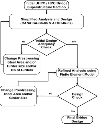
Proposed Iterative Design ProcedureThe iterative design procedure proposed for prestressed UHPC bridge is illustrated in Figure 4. The procedure involves two steps: (i) a simplified semi-analytical approach to obtain the preliminary feasible superstructure design; and then (ii) a refined finite element based analysis is carried out to check that the preliminary design is acceptable and if necessary modifications are required. The refined analysis generates a detailed stress distribution in all girders that enable to identify the zones of maximum stresses and to optimize the girder section and prestressing steel area and layout.
In order to verify the structural efficiency of UHPC bridge girders, a comparative study is conducted between two girder bridges having a conventional concrete slab compositely
23 integrated with HPC girders in the first bridge system, and a slab of the same geometrical and material properties is compositely integrated with UHPC girders in the second system. Both bridges are designed to have the same capacity, i.e. support the same traffic and superimposed dead loads. The major parameters in this comparison are the number of girders (or the girder spacing), the girder size, stresses at SLS, the girders deformations under service loads and the ultimate bridge load capacity. Other parameters such as the slab thickness, span length, number of lanes, traffic speed, prestressing system pattern, and boundary conditions are assumed the same for both bridges. The traffic load and bridge design is complying with all Serviceability and Ultimate Limit States (SLS and ULS) requirements of CHBDC (2006), however the material reduction factors are as shown earlier. The bridge girders are designed for no crack at transfer and serviceability limit states.
The bridge center-to-center span is 25 m and the total width of the deck including the barrier walls is 11.6 m. The slab thickness for both bridges is 175 mm, which corresponds to the minimum slab thickness accepted in the Canadian Bridge Code. According to CHBDC (2006), the assumed deck width can accommodate two or three design lanes. Two types of live loads are applied on the deck surface, lane loading and a single moving truck. For multi-lane loading, modification factors of 0.9 and 0.8 are applied for the two lanes and three lanes, respectively.
In previous research on UHPC girders, only straight tendon pattern is investigated (Bierwagen and Abu-Hawash 2004; Hajar et al. 2004; FHWA-HRT-06-115 2006), where the prestressing tendons are located in the bottom flange of the UHPC girders. In some
cases, a small amount of prestressing steel, mostly two tendons, are added in the top flange. In the present research, a dual tendon pattern is selected for both HPC and UHPC bridges. The dual prestressing tendon system is made up of two tendon groups: (i) a straight tendons group in the bottom girder flange, and (ii) a conventional deflected strands from top to bottom flanges. The structural advantages of using the dual tendon pattern for UHPC girders are investigated here, however, its effect on the fiber orientation is not studied.
Low-relaxation seven-wire strands, Grade 1860, with nominal diameter of 12.7 mm, nominal area of 98.7 mm2, and tensile strength (fpu) of 1860 MPa are used. CHBDC (2006) limits the minimum effective stress in tendons to 0.45 fpu, the maximum stress at jacking is limited to 0.78 fpu; the maximum tensile stress at transfer to 0.74 fpu; and the maximum stress at ultimate to 0.95 fpu. The total prestress losses are estimated to be 17% of the ultimate strength. The tendons for the HPC and UHPC girders are arranged in straight and conventional deflected strand patterns groups. The straight tendons provide 50% to 60% of the total prestressing steel area, depending on the maximum stresses in the girder. There was no need to deboned the strands near the supports as the tensile stresses remained below the allowable values for both UHPC and HPC bridges.
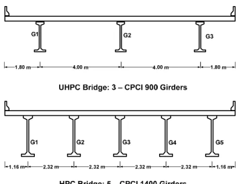
The materials properties of HPC bridge are selected to match the properties of similar existing bridges. The compressive strength of the slab concrete is taken as . For HPC girders, and at transfer . Five CPCI 1400 (Figure 5) are required for the HPC bridge with a girder spacing of 2.5 m. It is found that the use of twenty straight tendons at the bottom span and ten tendons linearly deflected on one third
MPa
fcs' =30
MPa
fcg' =40 fcgi' =30MPa
of the girder span are sufficient. The center of gravity (c.g.) of the straight tendons is 100 mm from the bottom fiber while the c.g. of the deflected tendon in the girder ends is 850 mm and in the middle third is 110 mm. The allowable compressive stress at transfer is
(or 18 MPa), and the allowable tensile stress at transfer is
' 6 . 0 fcgi ' 2 .
0 fcgi (or 1.1 MPa).
At SLS, the allowable compressive stress is (or 24 MPa) and the first crack
strength is ' 6 . 0 fcg ' 4 . 0 cg cr f
f = (or 2.53 MPa). The HPC bridge design is governed by the tensile strength or cracking limit at SLS. Short and long terms static deflections are very low and the vibration of bridge superstructure satisfies CHBDC (2006) requirements. For the ultimate limit state (ULS), the reduced flexural capacity of the girder is (7300 kN.m) higher than the factored moment (5440 kN.m). The factored moment resistance is far more than the cracking moment (3100 kN.m) and this satisfy CHBDC (2006) requirement for minimum reinforcement. The girder design is checked for ductile failure as the moment resistance is developed with c/dp = 0.074 far less than 0.5, where c and dp are defined in Figure 3. The shear reinforcement at the critical shear section is provided by 10M stirrups at 125 mm.
For the UHPC bridge, the compressive strength of the deck slab is assumed . The compressive strength of the ultra high performance concrete of the girders is and at transfer f (or 149 MPa). Three CPCI 900 (Figure 3) are found sufficient, with a girder spacing of 4.0 m. In order to use a small girder size and maximize the benefits of the very high strength of UHPC both in compression and tension, it is found that the optimum prestressing pattern is when the
MPa fcg' fcs' =30 ' cgi = ' 85 . 0 fcg MPa 175 = 25
ratio of deflected tendons to the straight tendons is between 0.8 and 1. In the present example, thirty-six straight tendons and thirty deflected tendons are found sufficient. The centre of gravity (c.g.) of the straight tendons is 90 mm from the bottom fiber while the c.g. of the deflected tendons at the girder ends is 600 mm and in the middle third is 220 mm. The allowable compressive stress at transfer is or (87 MPa) and the allowable tensile stress at transfer is 4.88 MPa. At SLS, the allowable compressive stress is 105 MPa and the cracking strength is 5.3 MPa. Similar to the HPC girder, the design of UHPC girders is also governed by the cracking limit at SLS. Short and long terms static deflections are within the acceptable limits and the vibration of bridge superstructure satisfy CHBDC (2006) requirements. For the ultimate limit state (ULS), the reduced flexural capacity of the UHPC girder is found (10,110 kN.m) higher than the factored moment (8,260 kN.m). In order to ensure that the reinforcement is more than the minimum limit according to CHBDC (2006), the factored moment resistance is far more than the cracking moment (3,470 kN.m). The girder design is checked for ductile failure as the moment resistance is developed with c/d = 0.085 far less than 0.5. The shear reinforcement at the critical shear section is provided by 10M stirrups at 100 mm spacing.
'
6 . 0 fcgi
Finite Element Modelling of UHPC Bridge
A linear elastic three-dimensional (3-D) finite element model (FEM) is developed to determine the stress distribution in all girders that make up the two investigated bridges. This 3-D FEM model enabled more accurate predictions of the stresses in all girders than the simplified analysis approach of the CHBDC (2006). Both the deck slab and girders are modeled using shell elements, while the prestressing tendons are modeled using cable
27 elements. The prestressing losses, deformations and relaxation are accounted in the model.
The FEM model enables to predict the stresses in every girder of the bridge and then optimizes the prestressing steel area and profile for better stress distributions. The FEM results indicate that the maximum stresses are found in the central girders for both HPC and UHPC for the case of two lanes loading. On the other hand, the maximum stresses are found in the external girders for the case of three-lanes loading. In general, the results show that the maximum stresses for the three-lane loading case are less critical than those of the two-lane loading case. It also shows that the most critical girders are the central girder (G3) for the HPC bridge and the internal girders (G2 or G3) for the UHPC bridge as shown in Figure 5. The optimum prestressing areas are found when the critical tensile stresses are equal to the SLS allowable values. The required prestressing steel from the finite element model is found to be lower by 10 to 15% than the value obtained by simplified analysis method, and the deflected strands profile is slightly different. The results of the finite element model also show that the compressive stresses at ULS in the top fibers at midspan and bottom fiber of support span of the critical girders identified above are well below the ultimate stress levels for both HPC and UHPC girders.
Comparison of Structural Efficiency of UHPC and HPC Bridges
The use of UHPC enables a considerable reduction in the concrete volume of up to two third when compared to HPC. The number of girders is reduced from five to three and the size of the girder is also reduced from CPCI 1400 to the minimum provided size CPCI 900. The weights of the girders per unit deck area of is 427 kg/m2 for the HPC bridge and
28 158 kg/m2 for the UHPC bridge. The total weight per unit area of the superstructure, including the deck slab are 847 kg/m2 for the HPC bridge and 578 kg/m2 for the UHPC bridge. Consequently, UHPC results in 32% reduction in the total weight of the
superstructure and 63% reduction in the girders weight. If the cement used for the HPC girders bridge is assumed equal to 380 kg/m3 and for UHPC is 1114 kg/m3 (Hajar et al. 2004), then for the bridge span of 25 m, a 7% reduction in the total cement needed to cast five CPCI 1400 HPC girders is realized when compared to the only three CPCI 900 UHPC girders needed. This reduced weight of UHPC superstructure will lead to a reduced size of the substructure.
It is clear that a reduction in the weight of the superstructure will lead to a reduced size of the substructure (piers and abutments) and foundations and reduced overall cost of the bridge. Furthermore, a reduction in the concrete consumption will have considerable environmental benefits through the reduction of energy consumption and greenhouse gas emission (GHG) associated with the production of cement, extraction and transportation of raw materials to the construction site (Lounis & Daigle 2007).
Summary and Conclusions
A simplified design approach of concrete slab on UHPC girders bridge is proposed. The use of the Canadian Highway Bridge Design Code, CHBDC (2006) and the current recommendations for design UHPC elements was investigated and a simplified flexural design approach has been derived. A closed form of the internal compressive force acting on UHPC precast/prestressed girder at ULS is given for all possible locations of the neutral axis. The proposed procedure suggests a simple and conservative sectional
29 analysis procedure similar to CHBDC procedure using a bilinear stress-strain model for UHPC under compression and ignoring the UHPC contribution to the tensile force.
For the investigated cases of 2 and 3 lane bridge with a 25 m span length, it is found that UHPC in precast/prestressed concrete girders yields a considerable reduction in the number of girders and girder size when compared to conventional HPC girders bridge, and hence results in a significant reduction in concrete volume and a slight reduction in the cement consumption. The dual prestressing tendon system suggested in the present study results in better stress distribution along the girder and hence more economical use of the material. This weight reduction leads to a more efficient design of the superstructure that reduces the weight on the substructure, which is very important for the safety of aging bridge substructures.
Further experimental work is needed to validate the proposed flexural design approach as well as shear strength of UHPC. Furthermore, the shape of girder sections can be improved for optimum use of the UHPC material.
References
American Association of State Highway and Transportation Officials 2007. AASHTO LRFD Bridge Design Specification, 4th Edition.
Acker, P., and Behloul, M. 2004. Ductal® Technology: a large spectrum of properties, a wide range of application, Proc. of the Int. Symp. on UHPC Kassel, Germany, pp.11-23.
30 AFGC Groupe de travail BFFUP, 2002. Ultra high performance fiber-reinforced
concretes: interim recommendations: Scientific and Technical Committee, Association Française de Genie Civil.
Almansour,H., Lounis, Z. 2007. Innovative precast bridge superstructure using ultra high performance concrete girders, Proc. of PCI 53rd National Bridge Conference.
Almansour,H, Lounis, Z. 2008. Structural performance of precast prestressed bridge girder built with ultra high performance concrete, Proc. of the Second International Symposium on UHPC, Kassel, Germany, pp 823-830.
BAEL 91 révisé 99. avril 1999. Règles techniques de conception et de calcul des ouvrages et constructions en béton armé suivante la méthode des états limites, Fasc. 62 (Titre premier, section 1 du CCTG).
BPEL 91 révisé 99. avril 1999. Règles techniques de conception et de calcul des ouvrages et constructions en béton précontraint suivante la méthode des états limites, Fasc. 62 (Titre premier, section 2 du CCTG).
Bierwagen, D., and Abu-Hawash, A. 2005. Ultra high performance concrete highway bridge, Proc. of the 2005 Mid-Continent Transportation Research Symposium, Ames, Iowa, pp.1-14.
Buitelaar, P. 2004. Heavy reinforced ultra high performance concrete, Proceedings of the Int. Symp. on UHPC, Kassel, Germany, September 13-15, pp.25-35.
Canadian Prestressed Concrete Institute. 1996. Design manual, precast and prestressed concrete, Third Edition.
Canadian Standards Association. 2006. CAN/CSA-S6-06: Canadian highway bridge design code.
31 Japan Society of Civil Engineers. September, 2006. Recommendation for design and
construction of ultra high strength fiber reinforced concrete structures (Draft), JSCE Guidelines for Concrete, No. 9.
Hajar, Z., Lecointre, D., Simon, A., and Petitjean, J. 2004. Design and construction of the world first ultra-high performance concrete road bridges, Proceedings of the Int. Symp. on UHPC, Kassel, Germany, pp.39-48.
Kim, S.W., Kang, S.T., Park, Ryu, G.S. 2008. Effect of filling method on fibre
orientation & dispersion and mechanical properties of UHPC, Proc. of the Second International Symposium on UHPC, Kassel, Germany, pp 185-192.
Lounis, Z., and Cohn, M.Z. 1993. Optimization of precast prestressed bridge girder systems, PCI Journal, V. 38, No. 4, pp 60-77.
Lounis, Z., and Mirza, M.S. 1997. High strength concrete in spliced prestressed concrete bridge girders. Proc. of PCI/FHWA Int. Symp. on High Performance Concrete, pp.39-59.
Lounis, Z., and Daigle, L. 2007. Environmental benefits of life cycle design of concrete bridges, 3rd International Conference on Life Cycle Management (Zurich, Switzerland, August 27, 2007), pp. 1-6.
Meda, A., Rosati, G. 2003. Design and construction of a bridge in very high performance fiber reinforced concrete, Journal of Bridge Engineering, Vol. 8, No. 5, pp.281-287. Pansuk, W., Sato, H., Sato, Y., Shionaga, R. 2008. Tensile behavior and fibre orientation
of UHPC, Proc. of the Second International Symposium on UHPC, Kassel, Germany, pp 161-168.
32 Parant, E., Rossi, P., Jacquelin, E., and Boulay, C. 2007. Strain rate effect on bending
behavior of new ultra-high-performance cement-based composite, ACI Materials Journal V. 104, No. 5, pp 458-463.
Rossi, P. 2008. Ultra high-performance concretes, a summary of current knowledge, Concrete International, pp 31-34.
Schnell, J., Ackermann, F.P., Rösch, R., and Sych, T. 2008. Statistical analysis of the fibre distribution in ultra high performance concrete using computer tomography, Proc. of the Second International Symposium on UHPC, Kassel, Germany, pp 145-152
Ulm, F. J., Acker, P. 2008. Nanoengineering UHPC materials and structures, Proc. of the second international symposium on UHPC, Kassel, Germany, pp 3-9.
U.S. Department of Transportation, Federal Highway Administration. 2006. Structural behavior of UHPC prestressed I-girders, Publication No. FHWA-HRT-06-115.
Walraven, J. 2008. On the way to design recommendations for UHPFRC, Proc. of the Second International Symposium on UHPC, Kassel, Germany, pp 45-56.
33
List of Figures
Figure 1. Mechanical properties of UHPC and HPC
Figure 2. Assumed tensile and compressive behavior of UHPC for design
Figure 3. Strain and Stress distribution at ULS of Flexural Action of UHPC Girders Figure 4. Design procedure for UHPC and HPC bridges
0.1 0.3 0.5 0.7 0.9 1.1 1.3 1.5 1.7 1.9 2.1 15 45 75 105 135 165 195 225 Com pressive stress M P a Strain % UHPC Typical HPC
Bi-Linear for Design
(a) 0.2 0.4 0.6 0.8 1.0 1.2 1.4 1.6 10 20 30 40 50 60 Displacement (mm) UHPC Typical HPC (b)
Figure 1. Mechanical properties of UHPC and HPC: (a) Stress-strain relationships, and (b) Flexural stress –displacement
' 60 . 0 fc c f = ' 484 . 0 3 . 0 c f t f K w t= = = ⎟⎟ ⎠ ⎞ ⎜⎜ ⎝ ⎛ σ σ ) ( ' 4 . 0 fc design cr f = f lim ) ( ' 65 . 0 design c f cu f = 003 . 0 = cu ε Actual Assumed cu f
Figure 2. Assumed tensile and compressive behavior of UHPC for design
tsla b Hs dp hft hfb rfu rfo c ac (a) tslab Hs dp bft be bfb bw hft hfb rfu rfo Aps Cc1 Cc2
T
pε
cu= 0.003 cε
bc= f’cgu/Ecgε
p fcguC
c ac (b)Figure 3. Strain and Stress distribution at ULS of Flexural Action of UHPC Girders: (a) Neutral axis in girder web, (b) Neutral axis in top flange
Figure 4. Design procedure for UHPC and HPC bridges
Figure 5. Comparison of HPC and UHPC precast/prestressed girders bridges