Publisher’s version / Version de l'éditeur:
Vous avez des questions? Nous pouvons vous aider. Pour communiquer directement avec un auteur, consultez la première page de la revue dans laquelle son article a été publié afin de trouver ses coordonnées. Si vous n’arrivez pas à les repérer, communiquez avec nous à PublicationsArchive-ArchivesPublications@nrc-cnrc.gc.ca.
Questions? Contact the NRC Publications Archive team at
PublicationsArchive-ArchivesPublications@nrc-cnrc.gc.ca. If you wish to email the authors directly, please see the first page of the publication for their contact information.
https://publications-cnrc.canada.ca/fra/droits
L’accès à ce site Web et l’utilisation de son contenu sont assujettis aux conditions présentées dans le site
LISEZ CES CONDITIONS ATTENTIVEMENT AVANT D’UTILISER CE SITE WEB.
Paper (National Research Council of Canada. Division of Building Research); no.
DBR-P-1214, 1984-03
READ THESE TERMS AND CONDITIONS CAREFULLY BEFORE USING THIS WEBSITE. https://nrc-publications.canada.ca/eng/copyright
NRC Publications Archive Record / Notice des Archives des publications du CNRC :
https://nrc-publications.canada.ca/eng/view/object/?id=4914c0fb-be73-4f0f-b343-b26a95fb1244 https://publications-cnrc.canada.ca/fra/voir/objet/?id=4914c0fb-be73-4f0f-b343-b26a95fb1244
NRC Publications Archive
Archives des publications du CNRC
This publication could be one of several versions: author’s original, accepted manuscript or the publisher’s version. / La version de cette publication peut être l’une des suivantes : la version prépublication de l’auteur, la version acceptée du manuscrit ou la version de l’éditeur.
For the publisher’s version, please access the DOI link below./ Pour consulter la version de l’éditeur, utilisez le lien DOI ci-dessous.
https://doi.org/10.4224/40001720
Access and use of this website and the material on it are subject to the Terms and Conditions set forth at
A procedure to calculate fire resistance of structural members
-- - Ser
THl
National Research
Conseil national
no. 1214
Council Canada
de
recherches Canada
c . 2
A PROCEDURE TO CALCULATE FIRE RESISTANCE OF STRUCTURAL MEMBERS
by T.T. Lie
Reprinted from Fire and Materials Vol. 8, No. 1, 1984 p. 40
-
48DBR Paper No. 1214
Division of Building Research
L e s progr'es r'ealis'es d a n s l e domaine du c a l c u l d e l a r t h i s t a n c e a u f e u o n t Et'e r a p i d e s c e s d e r n i k e s ann'ees. Une mgthode a bt'e m i s e a u p o i n t a u C o n s e i l n a t i o n a l d e r e c h e r c h e s du Canada pour c a l c u l e r l a r g s i s t a n c e a u f e u d e s E l & e n t s d e s t r u c t u r e . Q s diff'erentes & a p e s d e l a modGlisation m a t h b a t i q u e pour l e c a l c u l d e s temp'eratures, d e s d'ef o r m a t i o n s e t d e l a r ' e s i s t a n c e s o n t pr'esent'ees d a n s c e t t e n o t e e n u t i l i s a n t comme exemple l e c a l c u l d e l a r ' e s i s t a n c e a u f e u d t u n p o t e a u d ' a c i e r t u b u l a i r e r e m p l i d e b'eton. L' a u t e u r e f f e c t u e 6galement u n e comparaison d e s r ' e s u l t a t s o b t e n u s e n u t i l i s a n t l e mod8le a v e c ceux o b t e n u s
A
Procedure to Calculate Fire Resistance of
Structural Members
T. T. Lie
National Research Council Canada, Division of Building Research, Ottawa, Canada KIA OR6
Progress in the field of theoretical prediction of fire resistance has been rapid in recent years. A procedure has been developed at the National Research Council of Canada for calculation of the 6re resistance of structural members. The various steps in the construction of a mathematical model to calculate temperatures, deformations and strength are shown using as an example the calculation of the fire resistance of a cylindrical
tubular steel column fined with concrete. A comparison of results calculated using the model with those of a fire test is also discussed.
INTRODUrnON S T E E L - C O N C R E T E . \ B O U N D A R Y
,,
The lire resistance of various structural members such as beams, columns and walls can be determined by testing. In many cases, however, it can also be deter- mined by calculation. Progress in the field of theoreti- cal prediction of fire resistance has been rapid in recent years.
A procedure has been developed at the National Research Council of Canada for the calculation of the fire resistance of structural members. The calculation of fire resistance of a cylindrical tubular steel column, for which no method exists at present, is discussed as an example. The various steps in the construction of a mathematical model to calculate temperatures, defor- mations and strength of the column are shown. A comparison of results calculated using the model with I those of a fire test is also discussed.
B O U N D A R Y F I R E - S T E E L
I
Figure 1. Arrangement of elementaw layers in section of TEMPERATURE IN COLUMN concrete-filled tubular steel column.
I
I
The temperature in the column is calculated by a finite
difference method.' The method of deriving the heat also 4(A() thick. The thickness of all other layers in the transfer equations and calculating the temperatures in steel is A(. This is also the thickness of the layer of objects exposed to heat is described in detail in vari- concrete at the boundary between steel and concrete, ous publication^,^'^ and will not be discussed here; and that at the center of the column. The thickness of only the equations used for the calculation of the the other layers in the concrete is equal to 2(A(). column temperatures will be given.
Temperature calculations Division of cross-section into elementary layers
It is assumed that the entire surface of the column is The cross-sectional area of the column is subdivided exposed to the heat of a fire whose temperature course into a number of concentric layers. As illustrated in follows that of the standard fire described in ASTM- Fig. 1, along any radius a point P,, representing the ~ 1 1 9 . ~ This temperature course can be described by temperature of a layer ( m ) , is located at a distance the following expre~sion:~
( m -
l)A1
from the There are M1 layers inT: = 20 + 750[1- exp (-3.79553 J(?))] + 170.41 J(?) the steel and ( ( M , - M,)/2)
+
1 layers in the concrete.M, and MI are selected in such a way that M2- MI is (1)
an even number. The outer layer of steel, which is where 7 is the time in hours.
exposed to fire, has a thickness of $(A(). The layer of The temperature rise in each layer can be derived
I
steel at the boundary between steel and concrete is by making a heat balance for it. For an elementaryA PROCEDURE TO CALCULATE FIRE RESISTANCE OF STRUCTURAL MEMBERS
layer at the surface of the column, the temperature at a time T = (j+
AT
is given by the exp~ession:- (T,'
+
273)41)A~For the layers in the steel, except for the boundary layers, the temperature rise at time T = ( ~ + ~ ) A T , is given by
x (kip,
+
km')(Ti-l - T,')- 2 - m -
+
+ l-I
(3)For the layer at the boundary between the steel and concrete the temperature rise at time T = (j+
AT
isFor the layers in the concrete, except for the layer at the boundary between the concrete and steel and the center layer, the temperature rise at time T = (j+ AT,
is given by
x [(M,
-
rn+
l)(k',-,+
kmi)(T',-,- Tmi)- ( M - m - 1 ) ( k i
+
k )- T I (5)For the center concrete layer, the temperature rise at time T = (j
+
AT, is given byStability criterion
In order to ensure that any error existing in the solution at some time level will not be amplified in the subsequent calculations, a stability criterion has to be satisfied; for a selected value of At, this limits the maximum time step. For the column exposed to fire, the criterion of stability is most restrictive along the boundary between fire and steel. It is given by the condition
where ( p , c J ~ , is the minimum value of the heat capacity of the steel, k, the maximum value of its thermal conductivity and h,, the maximum value of the coefficient of heat transfer to be expected during the exposure to fire. Approximate values for these quantities are
(p,cJ-, = 3.6 x
lo6
J mp3 K-I (kJ,, = 47 W m-I K-Ih,, = 4a(TJ3 = 675 W mp2 K-I for T, = 1500 K
Effect of moisture
The effect of moisture in the concrete is taken into account by assuming that in each layer the moisture starts to evaporate when the temperature reaches
100°C. In the period of evaporation, all the heat
supplied to a layer is used for evaporation of the moisture until the layer is dry. From a heat balance equation, it can be derived that, per unit length of the column, the volume of moisture AVM1, evaporated in time AT from the concrete layer at the boundary between steel and concrete, is
The total volume of moisture in this layer is
VMl = n(2M2-2Ml - l ) ( A ~ ) ~ b , (9)
Similarly, it can be derived that the volume of moisture AV,, evaporated in the time AT from a layer inside the concrete, i.e. not located at the boundaries, is
The total volume of moisture in an inside concrete layer is
vm
= 4.rr(M2- m)(A02+, (1 1)For the center, the volume of moisture AVM2 evapo- rated from the concrete in the time AT is
The total volume of moisture in the center layer is
VM2 = d A t ) 2 b 2 (13)
With the aid of Eqns (1)-(13), and the relevant material properties given in the Appendix, the temper- ature distribution in the column and on its surface can be calculated for any time, T = ( j
+
AT, if the temper- ature distribution at the timeAT
is known. Startingfrom an initial temperature of 20 "C, the temperature history of the column can be calculated by repeated application of Eqns (1)-(13).
STRENGTH OF COLUMN
Division of cross-section into annular elements
To calculate the deformations and stresses in the column, the cross sectional area of the column is subdivided into a number of annular elements. In Fig. 2 the arrangement of the elements is shown in a quarter section of the column. The arrangement of elements in the three other quarter sections is identical to this. In radial direction the subdivision is the same as that shown in Fig. 1, where the cross-section is divided into concentric layers. In tangential direction each quarter layer is divided into N1 elements. The temperature representative of an element is assumed to be that at the center of the element. It is obtained by taking the average of the temperatures at the tangential boundaries of each element, previously cal- culated with the aid of Eqns (1)-(13).
Thus for an element P,,, in the steel, the represen- tative temperature is
and for an element P,,, in the concrete ( ~ ~ , ~ ) a n n ~ , a r = (*'-I
+
TL+l)
layer
(15) where the subscripts annular and layer refer to the annular elements shown in Fig. 2 and the element layers shown in Fig. 1.
Similarly it is assumed that the stresses and defor- mations at the center of an element are representative of the whole element.
Calculation of strength during fire
During exposure to fire the strength of the column decreases with the duration of exposure. The strength of the column can be calculated by a method based on a load deflection analysis described by Allen and ~ i e . ~ In this method, the columns, which are fixed at the ends during the tests, are idealized as pin-ended col- umns of length KL (Fig. 3). The load on the column is intended to be concentric. Due to imperfections of the columns and the loading device, a small eccentricity, e = 0.1 in (2.5 rnrn), is assumed.
The curvature of the column is assumed to vary from pin-end to mid-height according to a straight line elation, as illustrated in Fig. 3. For such a relation the deflection at mid-height y, in terms of the curvature
x
of the column at this height, can be given byFor any given curvature, and thus for any given deflec- tion at mid-height, the axial strain is varied until the internal moment at the mid-section is in equilibrium with the applied moment given by the product
load x (deflection
+
eccentricity)In this way a load deflection curve can be calculated for specific times during the exposure to fire. From these curves the strength of the column, i.e. the max- imum load that the column can carry, can be deter- mined for each time. In the calculation of column strength the following assumptions were further made: (1) The properties of the concrete and steel are those
described below and in the Appendix. (2) Concrete has no tensile strength. (3) Plane sections remain plane.
(4) Initial strains in the cross-section before the ex- posure to fire consist of free shrinkage of the concrete and creep. Because the shrinkage of the
J ~ /BOUNDARY - ~ ~FIRE-STEEL ~ ~
D E F L E C T I O N C U R V A T U R E
BOUNDARY Z - A X I S
' m 2 - 2 , N
STEEL-CONCRETE
Figure 2. Arrangement of elements in quarter section of
concrete-filled tubular steel column.
T
Figure 3. Load-deflection analysis.42 FIRE AND MATERIALS, VOL. 8, NO. 1, 1984
A PROCEDURE TO CALCULATE FIRE RESISTANCE OF STRUCTURAL MEMBERS
column during test was compensated by filling the spaces at both ends of the column between the concrete and steel with a plaster, the shrinkage is assumed to be negligible.
The tests of the columns are usually started after a preloading period of about 1 h. The shortening of the column due to creep during this period is assumed to be negligible. The initial creep can be eliminated by selecting the length of the shortened column as the reference length from which the axial strain of the column during the test is measured.
Based on these assumptions, the change of column strength during exposure to fire was calculated. In the calculations the network of annular elements shown in Fig. 2 was used. Because the strains and stresses of the elements are not symmetrical with respect to the x- axis, the calculations were performed for both the network shown and an identical network at the left of the x-axis. The load that the column can carry and the moments in the section were obtained by adding the loads carried by each element and the moments con- tributed by them.
The equations used in the calculation of the strength of the column during exposure to fire are given below. Equations for the steel
The strain in an element of the steel can be given as the sum of the thermal expansion of the steel (E,),, the axial strain of the column E and the strain due to bending of the column z , / p , where z, is the horizontal distance of the steel element to the vertical plane through the x-axis of the column section, and p is the radius of curvature. For the steel at the right of the x-axis the strain ( E & is given by
For the steel elements at the left of the x-axis the strain ( E , ) ~ is given by
Z
( E , ) ~ = - ( E , ) ~ + E ->
P (18)
The stresses in the elements of the network are
calculated using stress-strain relations derived from data provided by Ingberg and Sale,5 and by Witteveen et aL6 These relations include the effect of creep at elevated temperatures, and were obtained at heating rates that approximate real fire situations. The rela- tions have been generalized for other structural steels by assuming that, for a given temperature, the curves are the same for all steels, but the stress below which the stress-strain relation is linear is proportional to the yield strength of the steel. In Fig. 4 the stress-strain curves at 20°C are shown for two steels with a yield strength of 250 MPa and 345 MPa. For the 250 MPa steel a strain of 0.001 has been selected as the limit, up to which the stress is proportional to the strain. In Fig. 5 the stressstrain curves for steel with a yield strength of 345 MPa are shown for various tempera- tures. These curves show that even at the very high temperature of 800°C, the steel still possesses some strength and rigidity. The equations that describe the relation between the strength of the steel fy, the strain E,, and the temperature of the steel T are as follows: for E , S E , r f (T, 0.001) f y = 0.001 E s where E p = 4 x 10⁻⁶fyo (20) and f ( T , 0.001) = (50-0.04T) x [ I - exp ((-30+0.03T)J(0.001))] x 6.9 (21) For E , 3 E~ f (T, 0.001) f y = [ 0.001 ep+ f ( T , (E,- ~ ~ + 0 . 0 0 1 ) ) 1
-
f (T, 0.001)J (22) With the aid of Eqns (16)-(22) the stresses-at mid- section in the steel can be calculated for any value of the axial strain E and curvature l l p . From these stres- ses the load that the steel carries and the contribution of the steel to the moments can be derived.-
S T R A I N . 6
S T R A I N . €
Rgure 5. Stress-strain curves for 345-MPa steel at various Figure 4. Stress-strain curves for two steels at 20 O C . temperatures.
Equations for the concrete
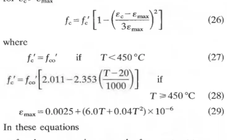
T. T. LIE for E,> E,,
The strain in the concrete for the elements at the right f c = f,' [I -
tc-
Ems.3&,,
)'I
(26)of the x-axis (Fig. 2) can be given by
zc where
( & c ) R = -(&T)c+ &
+-
P (23) f,'=fc,' if T<450°C ( 2 7 ) and for the elements at the left of the x-axis by
where ( E ~ ) , = the thermal expansion of the concrete
E =the axial strain of the column
zc = the horizontal distance from the center
of the element to the vertical plane through the x-axis of the column section
p =the radius of curvature.
The stresses in the elements are calculated using
stress-strain relations based on the work of ~ i t t e r ~
and H o g n e ~ t a d . ~ These relations, described in previ- ous s t ~ d i e s , ~ , ' ~ have been slightly modified to take into account the creep of concrete at elevated tempera- tures. The modifications are based on work by Schneider and Haksever9 and consist of a movement of the maxima in the stress-strain curves to higher strains with higher temperatures. These curves are
shown in Fig. 6 for a concrete with a cylinder strength
of 28 MPa. The equations that describe these curves
are as follows:
In these equations
fc = the compressive strength of concrete at temper-
I
ature T n q
f,' =the cylinder strength of concrete at temperature
T b
f,' =the cylinder strength of concrete at 20 OC
E , = strain of the concrete
E,, = the strain corresponding to maximum stress.
With the aid of Eqns (17)-(29) the stresses in each
of the steel and concrete elements at mid-section can be calculated for any value of the axial strain E and curvature l l p . From these stresses the load that the column carries and the contribution of each element to the internal moment at mid-section can be derived.
TEST
SPECIMENSfor E,S E,,
A number of test specimens consisting of cylindrical
)'I
(25) tubular steel columns filled with concrete were con-Emax structed for the purpose of verifying the mathematical ,
0 0 . 0 1 0 . 0 2 0 . 0 3 0 . 0 4
S T R A I N , E c
Figure 6. Stress-strain curves for 2&MPa concrete at various temperatures.
A PROCEDURE TO CALCULATE FIRE RESISTANCE OF STRUCTURAL MEMBERS
I
model described in the present paper. The concrete was made with an aggregate consisting of almost pure quartz. So far, two tests have been carried out on two similar specimens under different loads. The results of one test will serve as an example and as a comparison with predicted results.
The tubular steel column had an outside diameter of 273 mm and a wall thickness of 5.6 mm. Twenty-five- mm thick steel plates with dimensions of 508 mmx 610 rnrn were welded to the steel column at both ends. Holes with a diameter of 238 mm were cut in the steel plates, which were centered so as to give a lip of approximately 12 mm between the inside wall and the edge of the opening. In the tubular steel wall four holes of 12.5 mm diameter were drilled to provide openings through which the moisture in the column could escape. Two of the holes were located opposite one another at 1448 mm above mid-height of the column. The other two were also located opposite to one another at 1448 mm below mid-height of the column.
The concrete was poured in the column through the top opening. Its composition, per cubic meter of con- crete mix, was as follows:
Cement 366 kg Water 189 kg Sand (quartz) 660 kg Stone (quartz) 1120 kg
Chromel-alumel thermocouples 0.912mm thick were installed at mid-height of the column for measur- ing temperatures at different locations in the steel and concrete. One thermocouple was peened into the steel; one was installed 33 mm from the inner side of the steel wall; two were installed opposite to one another 66 mm from the steel. One thermocouple was located 98 mm from the steel and one approximately in the center of the column section, 125 mm from the steel.
-
I
TEST APPARATUSThe test was carried out by exposing the column to heat in a furnace specially built for the testing of loaded columns and walls. The test furnace was de- signed to produce the conditions to which a member might be subjected during a fire, such as high tempera-
,
tures, structural loads and heat transfer. It consists of a steel framework supported by four steel columns, with,
the furnace chamber inside the framework. The characteristics and instrumentation of the furnace are described in detail in Reference 10.The column was installed in the furnace by bolting its end-plates to a loading head at the top and a hydraulic jack at the bottom. Prior to installation the spaces between the concrete and the steel plates at the ends of the column were filled with plaster. The relative
humidity at mid-depth of the column prior to the start of the test was 98%, which corresponds to a moisture content in the concrete of approximately 10% by volume. The ambient temperature at the start of the test was about 20 "C.
The column was cast on 9 June 1981 and tested on 18 June 1982. The cylinder strength of the concrete at the test date was approximately 28 MPa. The steel was manufactured according to CSA Standard G 40.20- M1978,11 class H (hot-formed or cold-formed, stress- relieved), and had a specified yield strength of 350 MPa. The actual yield strength, measured on a sample cut from the steel of which the column was made, was 414 MPa.
The unfactored compressive resistance of the com- posite column, calculated according to CAN3-516.1- ~ 7 8 , ' ~ using a concrete compressive strength of 28 MPa and a specified steel strength of 350 MPa, was 2627 kN. The load on the column was 525 kN.
During the test the column was exposed to heating controlled so that the average temperature in the furnace followed as closely as possible the standard temperature-time curve given by Eqn (1). The temper- atures of the column were measured at the various locations described earlier. The axial strain of the column was also measured. The test was terminated when the column buckled.
RESULTS
AND DISCUSSIONThe measured and the calculated temperatures in the steel and at various locations in the concrete are shown in Figs 7-11. Steel temperatures are given in
900
-
O 600-
-
-
.-.
M E A S U R E D-
0 20 40 60 80 100 120 140 TIME, rninFigure 7. Steel temperature as a function of time.
T. T. LIE
TIME, min
Figure 8. Concrete temperature as a function of time (33 mm
from the steel).
.-.
500-
-
MEASURED C A L C U L A T E D U " 400-
Y E 3 ,C 300-
of w 0 I--
0 20 40 60 80 100 120 140 TIME, minFigure 9. Concrete temperature as a function of time (66 mm
from the steel).
.-.
M E A S U R E D 400-
U-
C A L C U L A T E D 0;
300-
3 C a E 200-
n I w I--
0 20 40 60 80 100 120 140 TIME, minFigure 10. Concrete temperature as a function of time (98 mm from the steel).
400
-
- -
M E A S U R E D U o C A L C U L A T E D 300-
3 C a5
200-
n I w I- t 0 20 40 60 80 100 120 140 TIME, min'
IFigure 11. Concrete temperature as a function of time (125 mm 4
from the steel). I
I
-
C A L C U L A T E DTIME, m l n
Figure 12. Axial elongation of column as a function of time.
Fig. 7. There is a good agreement between the meas- ured and the calculated steel temperatures.
In Fig. 8 the measured and the calculated tempera- tures at 33 mm from the steel are given. At this location the measured temperatures are lower than those calculated. The difference, however, reduces with increasing temperature and duration of the test. Near the failure point the difference is relatively small. In Fig. 9 the measured and the calculated tempera- tures at 66 rnm from the steel are given. The measured temperatures are the average of two readings. Up to about 50 min, measured temperatures are higher than those calculated. At a later stage there is a reasonably good agreement between calculated and measured
A PROCEDURE TO CALCULATE FIRE RESISTANCE OF STRUCTURAL MEMBERS temperatures. The rather rapid rise in temperature
followed by a period of nearly constant temperatures in the early stage of the test may result from thermally induced migration of moisture towards the center of the column. As shown in Figs 10 and 11, the influence of this migration is more pronounced for the deeper locations at 98 mm and 125 rnrn from the steel. At a later stage, however, which is the important stage from the point of view of predicting the fire resistance of the column, there is a good agreement between measured and calculated temperatures.
In Fig. 12 the measured and the calculated axial strains of the column during exposure to fire are shown. The shape of the calculated curve resembles that of the measured curve. The agreement in measured and calculated axial strains and column
temperatures indicates that, for the column under consideration, the mathematical model simulates with reasonable accuracy the conditions such as heat trans- fer, column deformations and stresses that occur dur- ing the exposure to fire. More tests under varied conditions are necessary, however, to confirm the proposed model as a valid method for the calculation of the fire resistance of concrete-filled steel columns.
Acknowledgement
This paper is a contribution from the Division of Building Research, of the National Research Council of Canada and is published with the approval of the Director of the Division. It was originally presented at the Three Decades of StructuraI Fire Safety Seminar at the Fire Research Station, Borehamwood, Herts (England).
APPENDIX: MATERIAL PROPERTIES AND PHYSICAL CONSTANTS
Instead of tabulated values, approximate equations are used in this study to describe the relationship between material properties and temperature. Except for those values for the thermal conductivity of concrete, the values are approximately the same as those used in the previous studies on reinforced concrete
For the thermal conductivity, values obtained from recent tests were used.14
Concrete properties
Thermal capacity of concrete for 0 S T S 2 0 0 ° C pccc = (0.005T+ 1.7) x
lo6
J rnp3 "C-' for 200 "C<
T S 400 "C for 400 "C<
T =S 500 "C p,c, = (0.013T-2.5) xlo6
J m-3 "C-' for 5 0 0 " C ~ T S 6 0 0 " C pccc = (-0.013T+ 10.5) xlo6
J m-3 "C-' for T>
600 "C pccc = 2.7 xlo6
J rnp3 "C-l Thermal conductivity of concretefor 0 S T S 8 0 0 ° C
kc = -0.00085T+ 1.9 W m-' "C-' for T
>
800 "Ckc = 1.22 W m-' "c-'
Coefficient of thermal expansion
Steel properties
Thermal capacity of steel
for O ~ T s 6 5 0 " C pscs = (0.004T+ 3.3) x
lo6
J rnp3 "C-' for 650 "C< T s 7 2 5 "C pscs = (0.068T- 38.3) xlo6
J m-3 "c-' for 725 "C<
T S 800 "C pscs= (-0.086T+73.35) xlo6
J m-3 "C-' for T>800 "C pscs = 4.55 xlo6
J m-3 "C-' Thermal conductivity of steelfor 0 S T S 9 0 0 ° C
k,= -0.022T+48 W m-l "C-' for T
>
900 "Ck , = 28.2 W m-' "C-'
Coefficient of thermal expansion for T
<
1000 "C a, = (0.004T+ 12) x for T 3 1000 "C a, = 16xlop6
Water properties Thermal capacity pwcw = 4.2 xlop6
J rnp3 "C-' Heat of vaporization A, = 2.3 x 10⁶ J kg-' Physical constantsa = Stefan-Boltzmann constant: 5.67 X
lo-'
W m-2 K-'E* = emissivity of fire: 1
E , = emissivity of steel: 0.9
NOMENCLATURE
Notations
specific heat (J kgp1 "C-') eccentricity of load (m)
compressive strength of concrete at temperature T (MPa)
cylinder strength of concrete at tempera- ture T (MPa)
cylinder strength of concrete at room temperature (MPa)
strength of steel at temperature T (MPa) yield strength of steel at room tempera- ture (MPa)
coefficient of heat transfer at fire exposed surf ace (W m-2 "C-')
thermal conductivity (W m-I "C-l) effective length factor
unsupported length of column (m) number of points P in the steel section in radial direction
total number of points P in the column section in radial direction
number of elements in tangential direc- t ion
point
temperature ("C)
Greek letters
coordinate
volume of water in an element (m3) lateral deflection of column at mid-height ( 4 coordinate subscripts max min n, Nl L R P Superscripts increment or difference mesh width (m) emissivity, strain (m m-l) heat of vaporization (J kg-')
density (kg m-3), radius of curvature (m) Stefan-Boltzmann constant (W m-2 K-4)
time (h)
concentration of moisture (fraction of volume)
curvature of column at mid-height (m-l)
at room temperature of concrete
of the fire
at the points m, MI, M2 in radial direc- t ion
maximum minimum
at the points n, N, in tangential direction left of the x-axis
right of the x-axis
pertaining to proportional stress-strain relation
of steel
pertaining to temperature of water
a coefficient of thermal expansion j at r = jAr
REFERENCES
1. G. M. Dusinberre, Heat Transfer Calculations by Finite Differences, International Textbook Company, Scranton, PA, 1961.
2. .T. T. Lie and T. 2. Harmathy, A numerical procedure to
calculate the temperature of protected steel columns ex-
posed to fire. Fire Study No. 28, Division of Building
Research, National Research Council of Canada, NRCC 12535, 1972.
3. Standard methods of fire tests of building construction and
materials. ANSI/ASTM E l 1S79, ASTM, Philadelphia, 1979.
4. D. E. Allen and T. T. Lie, Further Studies of the Fire
Resistance of Reinforced Concrete Columns, National Re- search Council of Canada, Division of Building Research, NRCC 14047, 1974.
5. S. H. lngberg and P. D. Sale, in Proceedings of the Ameri-
can Society for Testing and Materials 26, 11 (1926).
6. J. Witteveen, L. Twilt and F. S. K. Bylaard, in Second
International Colloquium on Column Strength, LiBge, April, 1977.
7. W. Ritter, Die bauweise hennebique. Schweizerische
Bauzeitung 33, February, 1899.
8. E. Hognestad, A study of combined bending and axial load
in reinforced concrete members. University of Illinois En-
gineering Experiment Station Bulletin No. 399, Urbana,
Illinois, 1951.
9. U. Schneider and A. Haksever, Bestimmung der aquivalen-
ten Branddauer von statisch bestimmt gelaguten Stahl- betonbalken bei naturlichen Branden. Bericht des lnstituts fur Baustoffkunde und Stahlbetonbau der Technischen Uni-
versitat Braunschweig, Braunschweig, West Germany,
.
1976.
10. T. T. Lie, Canadian Journal o f Civil Engineering 7 (1980). 1
11. General requirements for rolled or welded structural qual-
ity steel. Canadian Standards Association Standards
,
G.40.20-M1977, Toronto, 1977.
12. Steel structures for buildings--limit states design. Cana- dian Standards Association Standards, CANSS16.1-M78, Part One, Toronto, 1978.
13. T. T. Lie and D. E. Allen, Calculation of the fire resistance of
reinforced concrete columns. National Research Council of Canada, Division of Building Research, NRCC 12797, 1972. 14. T. T. Lie and G. Williams-Leir, Fire and Materials 3 (1979).
Received 9 May 1983; accepted 1 August 1983
T h i s p a p e r , w h i l e b e i n g d i s t r i b u t e d i n r e p r i n t form by t h e D i v i s i o n of B u i l d i n g R e s e a r c h , remains t h e c o p y r i g h t of t h e o r i g i n a l p u b l i s h e r . It s h o u l d n o t be r e p r o d u c e d i n whole o r i n p a r t w i t h o u t t h e p e r m i s s i o n of t h e p u b l i s h e r . A l i s t of a l l p u b l i c a t i o n s a v a i l a b l e from t h e D i v i s i o n may be o b t a i n e d by w r i t i n g t o t h e P u b l i c a t i o n s S e c t i o n , D i v i s i o n o f B u i l d i n g R e s e a r c h , N a t i o n a l R e s e a r c h C o u n c i l of C a n a d a , O t t a w a , O n t a r i o ,