Publisher’s version / Version de l'éditeur:
Vous avez des questions? Nous pouvons vous aider. Pour communiquer directement avec un auteur, consultez la première page de la revue dans laquelle son article a été publié afin de trouver ses coordonnées. Si vous n’arrivez pas à les repérer, communiquez avec nous à PublicationsArchive-ArchivesPublications@nrc-cnrc.gc.ca.
Questions? Contact the NRC Publications Archive team at
PublicationsArchive-ArchivesPublications@nrc-cnrc.gc.ca. If you wish to email the authors directly, please see the first page of the publication for their contact information.
https://publications-cnrc.canada.ca/fra/droits
L’accès à ce site Web et l’utilisation de son contenu sont assujettis aux conditions présentées dans le site LISEZ CES CONDITIONS ATTENTIVEMENT AVANT D’UTILISER CE SITE WEB.
Fire Study (National Research Council of Canada. Division of Building Research),
1974-08
READ THESE TERMS AND CONDITIONS CAREFULLY BEFORE USING THIS WEBSITE.
https://nrc-publications.canada.ca/eng/copyright
NRC Publications Archive Record / Notice des Archives des publications du CNRC : https://nrc-publications.canada.ca/eng/view/object/?id=121ef6b2-53b9-4873-acc1-32614fd66031 https://publications-cnrc.canada.ca/fra/voir/objet/?id=121ef6b2-53b9-4873-acc1-32614fd66031
NRC Publications Archive
Archives des publications du CNRC
For the publisher’s version, please access the DOI link below./ Pour consulter la version de l’éditeur, utilisez le lien DOI ci-dessous.
https://doi.org/10.4224/40001357
Access and use of this website and the material on it are subject to the Terms and Conditions set forth at
Fire tests on protected steel columns under different fire severities
Konicek, L.; Lie, T. T.
NATIONAL RESEARCH COUNCIL OF CANADA DIVISION OF BUILDING RESEARCH
FIRE TESTS ON PROTECTED STEEL COLUMNS UNDER DIFFERENT FIRE SEVERITIES
L . Konicek and T . T . Lie
F i r e Study No. 34 of the
Division of Building Re s e a r c h
Ottawa August 19 74
FIRE TESTS ON PROTECTED STEEL COLUMNS UNDER DIFFERENT FIRE SEVERITIES
L. Konicek and T. T. Lie
Six f i r e t e s t s were conducted t o provide experimental data which would verify computer calculations of temperature course in f i r e protected s t e e l columns exposed t o different s e v e r i t i e s of f i r e .
DES ESSAIS D'INCENDIE DE
S~VE/RITE/
VARIABLE SUR DES POTEAUX DIACIER P R O T I ~ G I ~L. Konicek et T. T. Lie
On a fait six e s s a i s dlincendie en vue d'obtenir de s donnCe s expgrirnentale s servant
'a
vCrifier d e s calculs p a r ordina- t e u r de l a courbe de tempkrature dans d e s poteaux d ' a c i e r protCgCs contre le feu e t exposCs'a
d e s incendies de SCVC- ritC diffCrsnte.F I R E TESTS ON PROTECTED S T E E L COLUMNS UNDER DIFFERENT F I R E SEVERITIES
by
L. Konicek'g and T. T . Lie**
M a t h e m a t i c a l e x p r e s s i o n s d e s c r i b i n g the t e m p e r a t u r e c o u r s e f o r different f i r e s e v e r i t i e s have been developed (1). Taking into consideration s e v e r a l significant p a r a m e t e r s i. e . the opening f a c t o r , the t h e r m a l p r o p e r t i e s of the wall m a t e r i a l s of a c o m p a r t m e n t and the f i r e load, it i s possible t o define a t i m e - t e m p e r a t u r e c u r v e which
r e p r e s e n t s the t e m p e r a t u r e c o u r s e of a ventilation controlled f i r e i n a p a r t i c u l a r c o m p a r t m e n t . Assuming t h e f i r e load is known, the f i r e t e m p e r a t u r e -time r e l a t i o n can be extended even t o the d e c a y p e r i o d of the f i r e , which s t i l l b r i n g s a potential d a n g e r of f a i l u r e t o load- b e a r i n g construction.
Knowledge of f i r e conditions r e p r e s e n t e d by the s e t of newly developed t i m e - t e m p e r a t u r e c u r v e s c a n be d i r e c t l y applied to f i r e
protection design. A s a f i r s t s t e p in t h i s d i r e c t i o n , a c o m p u t e r p r o g r a m w a s developed t o calculate a t e m p e r a t u r e distribution i n s t e e l columns with box type f i r e protection f o r t h e growth and d e c a y p e r i o d s of a f i r e .
A s a verification of t h i s t h e o r e t i c a l work, a s e r i e s of s i x t e s t s w a s c a r r i e d out. F u r n a c e t e m p e r a t u r e w a s r u n according t o a
s e l e c t e d t i m e - t e m p e r a t u r e curve d e s c r i b i n g growth and d e c a y p e r i o d s of a f i r e . T e m p e r a t u r e s developed in the s t e e l e l e m e n t s w e r e o b s e r v e d and c o m p a r e d t o calculated values. The r e s u l t s of t h e s e t e s t s and t h e i r c o m p a r i s o n t o t h e o r e t i c a l values a r e p r e s e n t e d in t h i s r e p o r t .
DESCRIPTION O F F I R E PROTECTIVE MATERIAL ( 2 )
All s p e c i m e n s w e r e protected by 1 -in. thick Vicuclad b o a r d s cemented t o g e t h e r and t o the s t e e l with a n adhesive m o r t a r . The b o a r d s a r e produced f r o m specially s e l e c t e d v e r m i c u l i t e which, a f t e r
*
S t e e l I n d u s t r i e s Fellow, F i r e R e s e a r c h Section, Division of BuildingRe s e a r c h , National R e s e a r c h Council of Canada.
*:g R e s e a r c h Officer, F i r e R e s e a r c h Section, Division of Building Re s e a r c h , National R e s e a r c h Council of Canada.
p r e - t r e a t m e n t , i s bonded with an inorganic binder t o produce a non- combustible board. The technical d a t a concerning Vicuclad have been provided by William Kenyon and Sons (Vicuclad) Ltd., C h e s h i r e , England. T h e r m a l conductivity of protective m a t e r i a l a t elevated t e m p e r a t u r e s w a s d e t e r m i n e d a t the National R e s e a r c h Council of Canada, Division of Buil.ding R e s e a r c h , F i r e R e s e a r c h Section. The data used f o r computation of s t e e l t e m p e r a t u r e c o u r s e s a r e p r e s e n t e d in Table I of t h i s r e p o r t .
DESCRIPTION OF S T E E L ELEMENTS
The wide flange s t e e l columns with welded s t e e l end p l a t e s w e r e used f o r e x p e r i m e n t a l work. The p a r a m e t e r s of t h e i r c r o s s -
sections specified in Table11 w e r e applied during t h e computer c a l c u l a - tions of p a r t i c u l a r t e m p e r a t u r e c o u r s e s in s t e e l under the f i r e conditions.
DESCRIPTION O F TEST SPECIMENS
The wide flange columns w e r e fitted with nogging p i e c e s of 1 -in. thick Vicuclad, fixed between the flanges and t o the web with
adhesive m o r t a r . The noggings w e r e spaced at 2-ft c e n t r e s on e a c h side of the column. The Vicuclad panels w e r e fixed t o the outer f a c e s of the f l a n g e s with the s a m e adhesive m o r t a r . To complete the e n c a s e m e n t , additional panels w e r e fixed t o the noggings and t o Vicuclad panels a l r e a d y in place. The d e t a i l s of the column e n c a s e m e n t a r e shown in F i g u r e s 1 , and 2 -
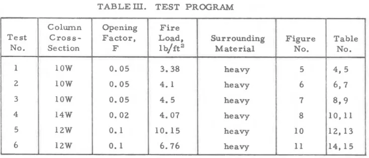
TEST PROCEDURE
The t e s t s w e r e c a r r i e d out according t o t h e p r o g r a m which is p r e s e n t e d in Table 111. The columns w e r e t e s t e d v e r t i c a l l y i n a g a s - f i r e d f u r n a c e . The furnace t e m p e r a t u r e w a s m e a s u r e d by nine t h e r m o -
couples positioned s y m m e t r i c a l l y about the column a s shown in F i g u r e s 3 , and 4.
The thermocouples w e r e enclosed i n 1/2-in. black i r o n pipe with a c a r b o n s t e e l c a p a t the tip. The hot junction of the thermocouples w a s placed 12 in. away f r o m t h e s u r f a c e of the specimen. The individual t e m p e r a t u r e s a t the nine points w e r e r e c o r d e d during the t e s t .
Since the p r e s c r i b e d t i m e - t e m p e r a t u r e c u r v e s differ f r o m the Standard T i m e - T e m p e r a t u r e c u r v e ( 3 ) , the fuel input t o the f u r n a c e was controlled manually.
The t e m p e r a t u r e of the s t e e l columns was m e a s u r e d by t h e r m o - couples peened into the s t e e l a t five levels. The location of t h e s e
OBSERVATIONS
The cladding r e m a i n e d intact throughout the t e s t without excep- tion. Towards the end of the longer t e s t s , c r a c k s developed in the v e r t i c a l joints of the Vicuclad panels. The s t r u c t u r a l s t r e n g t h of the e n c a s e m e n t was noticeably affected by the t e s t and in s e v e r a l i n s t a n c e s p i e c e s of the Vicuclad panels f e l l away f r o m the column a s it w a s
being removed f r o m the f u r n a c e .
F i g u r e s
6
and 7 show a column before and a f t e r the f i r e t e s t . The d e t e r i o r a t i o n a t the joints, evident in F i g u r e 8 , i s typical of the longer t e s t s .RESULTS
The s t e e l t e m p e r a t u r e s w e r e m e a s u r e d on five l e v e l s in the v e r t i c a l direction ( F i g u r e 5). T h r e e of t h e m , l e v e l s 1 , 3 , and 5, w e r e plotted in p a r t i c u l a r f i g u r e s ( F i g u r e s
9
t o 15). T e m p e r a t u r e differences between level 1 and level 5 a r e in the range of 1 5 0 ° F .The m a x i m u m m e a s u r e d s t e e l t e m p e r a t u r e in e a c h t e s t was
compared to the calculated t e m p e r a t u r e . R e s u l t s of a l l t e s t s a r e in v e r y good a g r e e m e n t . Differences a r e in the range of 5 0 ° F (approximately 570 difference). The calculated t e m p e r a t u r e was always higher than the experimental, in the above -mentioned t e m p e r a t u r e range.
C ONC LUSION
The r e s u l t s of the t e s t s w e r e found t o be in c l o s e a g r e e m e n t
with computed values. T h i s v e r i f i e s the validity of the r e c e n t l y developed computer p r o g r a m .
Assuming that the s e t of t e m p e r a t u r e - t i m e c u r v e s u s e d i n t h i s study c h a r a c t e r i z e s with sufficient a c c u r a c y the s e v e r i t y of actual f i r e s , i t i s possible, given the t h e r m a l p r o p e r t i e s of the f i r e -protective
m a t e r i a l , t o u s e a cornputor p r o g r a m f o r the evaluation of the f i r e protection of s t e e l columns under any f i r e conditions found i n p r a c t i c e .
Application of t h i s method t o the engineering of f i r e -protection design can significantly reduce the n u m b e r of full s c a l e column t e s t s and improve the economy of building production.
REFERENCES
1. T. T. Lie: C h a r a c t e r i s t i c T e m p e r a t u r e C u r v e s f o r Various F i r e S e v e r i t i e s , f o r submission t o F i r e Technology, Ottawa, 1973.
2. W . W . Stanzak, T . T. Lie: F i r e T e s t s on P r o t e c t e d Steel Columns with Different C r o s s - S e c t i o n s , F i r e Study No. 30 of the Division of Building Re s e a r c h , National Re s e a r c h Council of Canada, Ottawa, F e b r u a r y 1973.
3 . Standard f o r F i r e T e s t s of Building Construction and M a t e r i a l s , U n d e r w r i t e r s ' L a b o r a t o r i e s of Canada, 1971.
TABLE I. THERMAL PROPERTIES OF FIRE PROTECTIVE MATERIAL
TABLE
II.
TECHNICAL PARAMETERS OF TESTED S T E E L COLUMNSLegend: W = weight of steel section per unit height.
D
=
heated perimeter, i. e . development ofTABLE
LII.
TEST PROGRAMSurrounding Figure Table
3 10W 0 . 0 5 4 . 5 heavy 7
8 , 9
I
1 56
14W I 12W 12W 0 . 0 2 0 . 1 I 0 . 1 4 . 0 7 1 0 . 1 56 . 7 6
heavy heavy heavy 8 10 11 1 0 , l l 1 2 , 1 3 1 4 , 1 5 -TABLE IV. FURNACE TEMPERATURES Opening F a c t o r F = 0.05 F i r e Load Q
=
3.38 lb/ft2Heavy Mate r i a l Surrounding
Time , L - F l a m e T e m p e r a t u r e 1 Decay Temperature
/
m i n i P r e s c r i b e d ,I
" F Expe rimental, " F Experimental, P r e s c r i b e d , 1590 " FI
1660 1550 1450 1330 1240 1180 10201
990 930 8 50 760 700 " F I i , 70 950 1290 1410 1500I
1540 1570 161 5 1620 1645 1660 1 60 65 7 0 75 80 85 I 1695i
I
161 2I
1525 1438 1350 1262 1175I
1088I
1000 Ii
91 2 I 825I
738 650 1700 9O I 95 100 105 110 115 120TABLE V. MEASURED AND CALCULATED STEEL TEMPERATURES Column "low" Opening F a c t o r F = 0.05
F i r e Load Q = 3.38 lb/ft2 Heavy M a t e r i a l Surrounding
Caleulated Steel T e m p e r a t u r e , O F 105.2 229.8 366.9 496.8 618.3 732.4 832.5 904.1 948.0 967.5 966.1 947.2 Time
L Measured Steel Temperature
I
Level 5, min. I O F Level 3, O F Level 1, O F I I I I 1 70I
70 I 70 150 2 50 360 1 10 O 120 135 230 40 20 205 30 425 31 0 1 ! 330 460 500I
50 550 601
680 70 760 80 825 I 90 840 100 845 I 110 835 630 ' 700 580 730 800 840 870 1 900 895 I 900 895 8 60 925 940 940 925TABLE VI. FURIL'ACE TEMPERATURES Opening F a c t o r
F
=
0.05 F i r e LoadQ =
4.1 lb/ft 2 Heavy M a t e r i a l Surrounding F l a m e T e m p e r a t u r e Decay T e m p e r a t u r e 1 -P r e s c r i b e d , "F 1400 147 5 1520 1540 1570 1700 E x p e r i m e n t a l ,"F
I
Ii
I ! I I1
I
i
7 5 t 80 I1
1675 ' 8 5 90 9 5 100 1 0 5 110 11 5 120 125 I 1651 i I I 130 135 1502 1 540 906j
935 1353 1204 140 145 150 4 1400 I i 1205 I 7 57 607 1055I
1055 770 57 0TABLE VII. MEASURED AND CALCULATED S T E E L TEMPERATURES Column "10W" F i r e Load Q
=
4.1 lb/ft 2 Opening F a c t o rF
=
0.05 Heavy M a t e r i a l Surrounding Calculated S t e e l T e m p e r a t u r e ,OF
I 70 105.2 229.8 366.9 496.8 61 8 . 3 732.4 839.9 938.4 1014.0 1065.0 1094.0 1103.7 1096.7 1075.5 1042. 5 T i m eI
1
min. J I Measured S t e e l T e m p e r a t u r e L e v e l 1,OF
70 10 2 22 5 335 475
59 0 Level 5, "F-
L e v e l 3,"F
70 9 5 195 325 460 57 5 01
701
10 85 2 01
30 11
40 50 715 185 30 5 4 50 5601
60 69 5 725 70 80 90 100 810 910 970 1010 1030 1040 1035 101 5 965 790 890 9 50 9 85 820 910 9 80 1035 1050 1060 1050 1035 99 5 11°I
1005 120 130 140 150 1005 990 975 9 30TABLE VIII. FURNACE TEMPERATURES
Opening Factor F
=
0.05 F i r e LoadQ
=
4. 5 lb/ft 2Heavy Material Surrounding
Time Flame Temperature
i
min. Decay Temperature Prescribed, OF Prescribed,1
Expe:kmental,OF
i
Experimental, OF IT A B L E IX. MEASURED
AND
CALCULATED S T E E L TEMPERATURES Column "1 OW" Opening F a c t o r F=
0 . 0 5L
F i r e Load
Q =
4. 5 lb/ft Heavy M a t e r i a l SurroundingCalculated S t e e l T e m p e r a t u r e ,
OF
70 105.2 229.8 366.9i
496.8I
618.3i
732.4I
I I 839.9 I 971.2i
1030.7 I t 1096.91
I1
T i m e L!
M e a s u r e d S t e e l T e m p e r a t u r e 110 l o o 1055I
1100I
L e v e l 1 , " F 70 145 240 1 II
Ii
Le:;i
i
L e v e l 3, min. 1150 1 I 0 70 10 125 201
220 1170.9I
1
"F
70 130 2 30 30 11
320 It
40 4651
50 r( 600 1 60j
70 5 701
81 0 8o1
905 I 9O1
9 80'
1025 1165.11
f 1172 I I 1163 I I 11721
120(
1080 1115 1 1175 340 360 490 50 5 61 5 630 I 7 30 7 50 835 855 935 9 60 1020 1050 I!
130'
1080 1070 140 150 1120 I 1170 1100 1065 1040 1100 1090 1150 1140T A B L E X. FURNACE T E M P E R A T U R E S Opening F a c t o r F = 0 . 0 2 F i r e Load Q = 4.07 lb/ft 2 Heavy M a t e r i a l S u r r o u n d i n g I T i m e L r n l r l . 0 5 10 1 5 20 2 5 30 3 5 40 4 5 50 55 60 6 5 7 0 7 5 80 8 5 9 0 9 5 100 1 0 5 110 1 1 5 120 1 2 5 130 1 3 5 140 1 4 5 150 1 5 5 160 1 6 5 170 175 1 XU 1x5 190 1 0 5 200 L O 5 210 Decay P r t . a r r i b n d . ' k' 7 0 1472 1442 1412 1382
1
1353 1323 215 220 225 L 30 235 240 24 5 2 50 255 2 60 265 270 275 2 HO 285 2YO 29 5 I 300 T e m p e r a t u r e Il;xpt!rinic-ntitl. "F 70 F l a m e T e m p e r a t u r e lJt.c:nc:ribt~d, EXPI-rimc.nti11. " F " k- - 70 688 9 2 8 1019 1058 1081 1099 1116 1134 1 1 5 3 1171 1190 1209 1293I
1263 1233 1204 1174 1144 11 14 1084 1055 1025 9 9 5 9 6 5 9 3 5 906 876 84 6 7 0 500 9 20 1010 1040 1075 1030 1160 1 1 60 1 1 80 1180 1 200 1240I
I
8161
786 1228 1246 1263 1280 1297 131 3 1328 1342 1356 1370 1382 1394 1406 1417 1 4 2 8 I 1438 1447 1456 1 4 6 5 1 4 7 3 1481 1488 1495 1 SO2 1250 1260 1270 1290 1300 1320 1350 1360 1370 13x0 1410 1420 1420 1430 1430 1450 1 4 6 5 1470 1470 1 4 8 5 1500 1500 1510 1520T A B L E XI MEASURED AND CALCULATED S T E E L TEMPERATURES
Column " 1 4 W" Opening Factor F
=
0. 02L
Fire Load Q
=
4. 07 lb/ft Heavy Material Surrounding!
I Time
j
! Measure Steel Temperature
L !
!
rnin.
1
~ e v e i 5, Level 3,I
Level 1,! !
OF
1
O FI
O Fi
1
Calculated Steel1
Temperature,1
F
I
T A B L E XI1 FURNACE TEMPERATURES L Opening F a c t o r F = 0. 1 F i r e Load Q = 10. 1 5 lb/ft Heavy M a t e r i a l Surrounding F l a m e T e m p e r a t u r e Decay T e m p e r a t u r e m i n .
,t
101
1 5 2 0 25 30 3 5 40 4 5 5 0 5 5 60 6 5 70 75 8 0 8 5 9 0 9 5 100 105 110 11 5 120 125 130 135 1 40 145 150 155 160 165 170 175 180 185 190 195 200 205 210 P r e s c r i b e d , O F E x p e r i m e n t a l , E x p e r i m e n t a l , O F1
FTABLE
XI11
MEASURED AND CALCULATED STEEL TEMPERATURES Column "1 2 W" Opening Factor F=
0. 12
Fire Load Q = 10. 15 l b h t Heavy Material Surrounding
I Time
i
Measured Steel Temperature Y f1
-1
L I 1 I , Calculated Steeli
II min. I Level 5, 1 Level 3, y Level 1, i
i
Temperature, " F >"
FE
OF
I
I " F I I I 1 ITABLE XIV FURNACE TEMPERATURES
L
Opening Factor F
=
0. 1 Fire LoadQ
=
6.76 lb/ft Light Material SurroundingI
1
I
Decay TemperatureI
Time L Flame Temperature I IExperimental, I Prescribed,
I
Experimental,OF ! OF
!
FI
min. Prescribed, OFI
0 70I
70 I 51
1010 980!
1539I
1260 15 l o 1675 1754t:
1
1800 30 1 1820 1500i
1650i
I
I 35 40 4 5 5 0 65 70 1720 1830 1870 18 50 1876 1900 1935 1965 1995 I II
1
75 I 80 85 901
95 19101
! 1950i'
1 1970 1975i
19701
1995i
1970 I 1905 Y 1920I
18141
18601
1724I
1700I
I
1633I
I 16201
1543 i 15201
1452 I 1470I
r
I I 1362 1360 1271 1275 105 110 115 120 125 1301
100i
1181 1190 I 1 I 1090 I 1100 1000 960 910)
870 820 810 730i
7 00-
TABLE X V MEASURED AND CALCULATED STEEL TEMPERATURES
Column "12 W" Opening Factor F
=
0 . 12
Fire Load Q
= 6 .
76 lb/ft Heavy Material SurroundingI
Measured Steel Temperaturet T i e
I
I Calculated Steel I I1
Level 3, Temperature,,
min. Level 5,!
" F"
F
I O F!
F I G U R E 1
I:'
-
T O T A L O F 9 T H E R M O C O U P L E S C E N T R A L TC O N O N E S I D E O N L Y
/
3 / 4 " PlPE U N I N S U L A T E D B L A C K I R O N C O L U M Nu
3 " BLACK I R O N PlPE I N S U L A T E DF I G U R E 3
L O C A T I O N O F F U R N A C E T H E R M O C O U P L E S
I N R E L A T I O N T O C O L U M N
V E R T I C A L S E C T I O N
H O R I Z O N T A L S E C T I O N
F I G U R E
4
D B R F L O O R F U R N A C E I M P R O V E D
B Y R E F L E C T I V E
D I S T A N C E F R O M THE B O T T O M 6
'
5'
L E V E L 3 4'
L E V E L 4 3'
L E V E L 5 2'
T H E R M O C O U P L E S L E V E L 4 L E V E L 5F I G U R E
5
L O C A T I O N O F T H E R M O C O U P L E S
O N W I D E F L A N G E C O L U M N S
I '-
T I M E , M I N .
F I G U R E 9
C O U R S E O F F U R N A C E A N D S T E E L T E M P E R A T U R E S , C O L U M N " l O W 1 ' , O P E N I N G F A C T O R
T I M E , M I N .
F I G U R E 1 0
C O U R S E O F F U R N A C E A N D S T E E L T E M P E R A T U R E S , C O L U M N " 1 O W " . O P E N I N G F A C T O R F = O . 05, F I R E L O A D Q = 4 . 1 L B I F T ~ , H E A V Y S U R R O U N D I N G M A T E R I A L S
1. S T E E L T E M P , L E V E L I 3 . S T E E L T E M P , L E V E L 3 5. S T E E L T E M P , L F V E L 5 2 . S T E E L T E M P , C A L C U L A T E D 4. F U R N A C E T E M P , E X PE
H
l M E N T A L 6. F U R N A C E T E M P , C A L C U L A T E Dl
I
I
1
I
l
I
l
I
1
1
I
1
1
1
1
0
10 2 0 3 0 4 0 5 0 6 0 70 80 90 100 I 2 0 130 1110 150 160 T I M E , M I N . F I G U R E 1 1 C O U R S E O F F U R N A C E A N D S T E E L T E M P E R A T U R E S , C O L U M N " l O W " , O P E N I N G F A C T O R F = 0 . 0 5 , F I R E L O A D Q = 4 . 5 L B I F T ~ , H E A V Y S U R R O U N D I N G M A T E R I A L ST I M E , M I N .
F I G U R E 1 2
C O U R S E O F F U R N A C E A N D S T E E L T E M P E R A T U R E , C O L U M N " 1 4 W " , O P E N l N G F A C T O R F = 0 . 0 2 , F l R E
s
3 3 0 -' e 0 E v 3 w-*
=
>z,'
a wE5
=
P.-
s
:
W LL I-- d m w - '1. S T E E L T E M P , L E V L L t 3. S T E E L T E M P , L E V E L 3 5 . S T E E L T E M P , L E V E L 5 2. S T E E L T E M P , C A L C U L A T E D 4. F U R N A C E T E M P , E X P E R I M E N T A L 6. F U R N A C E T E M P , C A L C U L A T E D