Publisher’s version / Version de l'éditeur:
Vous avez des questions? Nous pouvons vous aider. Pour communiquer directement avec un auteur, consultez la
première page de la revue dans laquelle son article a été publié afin de trouver ses coordonnées. Si vous n’arrivez pas à les repérer, communiquez avec nous à PublicationsArchive-ArchivesPublications@nrc-cnrc.gc.ca.
Questions? Contact the NRC Publications Archive team at
PublicationsArchive-ArchivesPublications@nrc-cnrc.gc.ca. If you wish to email the authors directly, please see the first page of the publication for their contact information.
https://publications-cnrc.canada.ca/fra/droits
L’accès à ce site Web et l’utilisation de son contenu sont assujettis aux conditions présentées dans le site LISEZ CES CONDITIONS ATTENTIVEMENT AVANT D’UTILISER CE SITE WEB.
Internal Report (National Research Council of Canada. Institute for Research in
Construction), 2000-10-01
READ THESE TERMS AND CONDITIONS CAREFULLY BEFORE USING THIS WEBSITE.
https://nrc-publications.canada.ca/eng/copyright
NRC Publications Archive Record / Notice des Archives des publications du CNRC :
https://nrc-publications.canada.ca/eng/view/object/?id=83399da7-0d4b-4833-ab95-9648d3132066
https://publications-cnrc.canada.ca/fra/voir/objet/?id=83399da7-0d4b-4833-ab95-9648d3132066
NRC Publications Archive
Archives des publications du CNRC
For the publisher’s version, please access the DOI link below./ Pour consulter la version de l’éditeur, utilisez le lien DOI ci-dessous.
https://doi.org/10.4224/20378489
Access and use of this website and the material on it are subject to the Terms and Conditions set forth at
Wind uplift resistance data of TPO roofing systems with new seaming
concepts
S e r
I TH1 National Research Conseil national Council Canada de recherches Canada
R 4 i i 7 I n o .
617
I
c.2
I
IR(Z
I
Institute for lnstitut de
Research recherche
in Construction en construction
Wind Uplift Resistance Data of
TPO
Roofing Systems with New Seaming
Concepts
G. Xu and A. Baskaran
Internal Report No. IRC-IR
817
Executive Summary
Developments of new field application technologies and tools in mechanically attached
Single Ply Roofs (SPR) have led to new seaming concepts. Conventionally, these
seams have an overlap of
5"with the fastener placed 1.5" from the edge of the under
sheet, and
3.5from the edge of the overlapping sheet. The portion of the seam beyond
the fastener row is welded with hot air such that a waterproof top surface is obtained.
The width of the welded portion varied between 1.5" and 1.75". This application is
termed as One Side Weld (OSW). Genflex Roofing Systems approached NRC' with a
concept of Double Side Weld (DSW). In the DSW, the fasteners are placed at the seam
middle and hot air welding is performed simultaneously on both sides of the fastener
row.
To investigate the DSW system performance under dynamic conditions and to compare
with those of the OSW systems, several investigations were completed. The
measurements were made in the Dynamic Roofing Facility (DRF) of the National
Research Council of Canada. More information about the DRF' s features was
documented by Baskaran and Lei (1997)'. For these investigations, SIGDERS dynamic
test protocol was used. Details of the test protocol were documented by Baskaran and
Nabhan (2000)~.
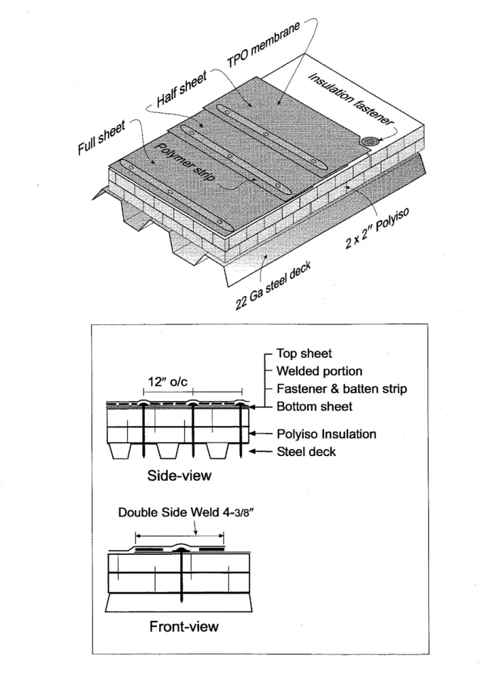
Ten experiments using five different systems were completed. Figures
1to 5 provide
isometric views of the used components in these systems whereas Tables 1 to
5group
component details and their nominal physical and mechanical properties. Figures
6to
10 show the layout of the sensors that were instrumented to quantify the system
response. Tables 6 and 7 summarize the statistics for the tested system response. By
following a common format as shown in Figure 11, Appendix 1 archive the system
response by means of the time history plots.
These data can be used to document a good practice guide for wind resistance of roofs
with flexible membrane. In addition, one can use these data to develop analytical tool to
forecast system rating.
'
Authors acknowledge GenFlex Roofing Systems for support. Authors also appreciate David Scott of GenFlex Roofing Systems and William Lei of NRC for the system installations.*
Baskaran, A. and Lei, W. (1997), "A New Facility for Dynamic Wind Performance Evaluation of Roofing Systems: Proceedings of the Fourth International Symposium on Roofing Technology, NRCA/NIST,Washington, D.C., U.S.A., pp. 168-179.
3 Baskaran, A and F. Nabhan, (ZOOO), "Standard Test Method for the Dynamic Wind Upliff Resistance of
Mechanically Attached Membrane Roofing Systems'; Internal Repofi IRC-IR 699, National Research Council, Canada.
r
Top sheet
Welded portion
Fasteners
8
plates
Bottom sheet
Polyiso Insulation
Steel deck
One Side Hot
Air Weld
4-318"P
!+ci
Top sheet
Welded portion
Fastener
& batten strip
Bottom sheet
Polyiso Insulation
Steel deck
Double Side Weld
4-318"I----_-L.l
Figore 2: System 2 -Double S~de Weld with Metal Batten Strips
Top sheet
Welded portion
12" olc
-
Fastener & batten strip
Bottom sheet
Polyiso Insulation
Steel deck
Side-view
Double Side Weld
4-318"j-
Top sheet
Welded portion
Fastener
&
batten strip
Bottom sheet
Polyiso Insulation
Steel deck
Double Side Weld
4-318''Figure 4 : System 4
-
System 3 with Full and Half Sheets LayoutTop sheet
Welded portion
12" olc
Fasteners
& plates
Bottom sheet
Polyiso Insulation
Steel deck
I
One Side Hot Air Weld
4-318"
i
,
Page 8 of 71
Table 1: System 1
-
Nominal physical and mechanical properties of the components (One Side Weld with Spot Fasteners)/
TypeI
Profiled metal sheeting 22-gaugeThickness
1
0.030 (0.76 mm)Depth
1
1.5" (38 mm)Flllte Snacinn
1
59" (150 mmb.
-E---... I . - - ...-,Fastener Pullout as per ANSIISPRI FX-1-1996*
1
470 lbf (21 20 N)I VirWest Steel I
lnsulation
Type
/
Polyiso ( E ' N R G ' Y ~ ~ )Dimension
/
2 boards of 4' x 8' (1218 mm x 2436 mm) xCompressive Strength as per ASTM D l 621 -94- Source AirNapor BarrierlRetarders
I
None used 2" thick (50.8 mrnj 18.8 psi (1 30 kPa) Johns Manville Insulation Attachmentf
i
embrane Fastener Plate Fastening Pattern SourceAssembled 5" (128 mm) screws & plates 3" (77 mm) plastic lock plate
4 fasteners per board Olympic Membrane
I_
I ype Width ThicknessTensile property as per ASTM D 751-98 (Grab)*
Attachment
TPO
74 718" (1 910 mm) 45 mil (1 .l mm)
MD XD
Breaking strength, kN (Ibf) 1.3(293) 1.1 (248)
Elongation at Max. load, % 29 29
-
Type Fastener" Plate
Fastener Row Spacing Fastener Spacing Slippage Control
Mechanical fasteners with plates 5" (128 mm) Genfast #15
2 38" (61 mm) Dia. metal plate
70
in"
(1 790 mm) 12" (305 mm) Yes Seam Type Seaming Weld ConditionHot air welding
Overlap: 4 38" (1 11 mm) Type: One Side Weld
Good Weld Cold Weld
Temperature: 950 'F (510
'
C
) 500 'F (260 'C )Speed: 7.9' Irnin(2.4m/min) 11.8'/min(3.6m/rnin)
Weight: 1 weight (6 lbs) 1 weight (6 lbs)
Table 2: System 2
-
Nominal physical and mechanical properties of the components (Double Side Weld with Metal Batten Strips)Type Thickness
Depth
Flute Spacing
Fastener Pullout as per ANSIISPRI FX-1-1996'
Sn, WPP
Insulation Attachment
Profiled metal sheettng 22-gauge 0.030" (0.76 mm)
1 . 5 (38 mm) 5 . 9 (150 mm)
470 lbf (2120 N)
VirwD~t S ~ D D ~
Compressive Strength as per ASTM D l 621 -94* Source 2" thick (50.8 mm) ' 18.8 psi (130 kPa) Johns Manville AirNapor BarrierlRetarders
I
None used Type Fastener Plate Fastening Pattern SourceMechanical fasteners with plates
Assembled 5 (128 mm) screws & plates 3 (77 mm) plastic lock plate
4 fasteners per board Olympic Membrane
.
. . -. .-
.--
.-
. .-
.-
. .., ;enfast #15 (XHD) -- :, u.u41" (1.20 mm)thi_ck- --. . . - Type Width ThicknessTensile property
as
per ASTM D 751-98 (Grab)'Membrane Attachment f u irz (1790 mm) 12" (305 mm)
.
, TPO 74 718" wide (1910 rnm) 45 mil (1 .l mm) MD XD Breaking strength, kN (lbf) 1.3(293) 1.1 (248)Elongation at Max. load, % 29 29
Type Fastener* Plate
Fastener Row Spacing Fastener Spacing Slippage Control
Seam
Metal batten strin and fasteners
I
5 (1 28 mm) C
1
"
wid€ ^ ^"--
. .-8,-
yes
I
Type
I
Hot air weldingSeaming
I
Overlap: 4 318" (11 1 rnm)I
Weld ConditionT e: Double Side Weld
Good Weld Cold Weld
Temperature: 950
V
(510 % ) 801 *F (427 'C ) Speed: 6.5'1rnin (2 mlmin) 9.8'lmin (3 mlmin) Weight: 1 weight (10 lbs.) 2 weight (2x10 lbs.)L
I
I
Position: in normal position inner side* NRC test results
Table 3: System 3
-
Nominal physical and mechanical properties of the components (Double Side Weld with Polymer Batten StripsJThickness
1
0.030 (0.76 mm) Depth -. - .1
1.5 (38 mm) ' i" (1 52 mm) i85 lbf (3050 N) Flute Spacing 16Fastener Pullout as per ANSIISPRI FX-1-1996-
16
Snl ~ r c e I
,
r
3anam SteelI
Insulation
Type
I
Polyiso (E'NRG'Y2IM)Dimension
1
2 boards of 4' x 8' (1218 mm x 2436 rnm) xzal fasteners with plates
28 mm) screws & plates
Plate
1
3" (77 mm) plastic lock plateFastening Pattern
/
4 fasteners per boardSnl l r ~ p I nltnnnir
Compressive Strength as per ASTM D l 621 -94* Source AirNapor Barriermetardew None used 2" thick (50.8 mm)' 18.8 psi (1 30 kPa) Johns Manville Membrane Type
/
TPOWidth
1
74 718" (1910mm) wide sheets, Lot # 30144,colorBreaking strength, kN (Ibf) 1.3(293) 1.1 (248)
Elongation at Max. load, % 29 29
Thickness
1
45 mil ( I . l mm)Membrane Attachment
Tensile property as per ASTM D 751-98 (Grab)
'
--- - -
-,
-nd fasteners1
MD XD Type Fastener*.
-
. .
-
,
. .
- -
. .
. . . .
-
. .
,
12" (305 mrn) . -. . -.I
Slippage ControlI
YesI
Polymer batter :!!; :
5" (128 mm) Genfast #15 (WH)
1
Ratten Strip 1" wide, 0.057" (1.45 mm) thicktener Rnw Snadnn 71) i 17" 11 741) mrnl
Seam Type Seaming
Hot air welding
Overlap: 4 318" (1 11 rnm) Type: Double Side Weld Welding Condition
Temperature: 950 'F (51 0 ' C )
Speed: 6.5'lmin (2 mlmin) Weight: 1 weight (10 lbs.) * NRC test results
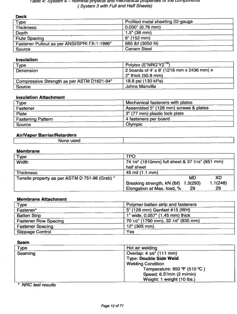
Table 4: System 4 - Nominal physical and mechanical properties of the components (System 3 with Full and Half Sheets)
Deck
Type
I
Profiled metal sheeting 22-gaugeThickness
1
0.030 (0.76 mrn)Insulation
Type
/
Polyiso(t'runtivz
)Dimension
1
2 boards of 4' x 8' (121 8 mm x 2436 rnm) xDepth
Flute Spacing
Fastener Pullout as per ANSIISPRI FX-1-1996' Source
1
2" thick (50.8 mm)Compressive Strength as per ASTM D1621-94'
1
18.8 psi (1 30 kPa)Source
I
Johns Manville1.5" (38 mm) 6 (1 52 rnm) 685 lbf (3050 N) Canarn Steel AirNapor BarrierIRetarders None used Insulation Attachment Membrane Type
/
TPOWidth
/
74 718" (1910mrn) full sheet & 37 7/16" (951 rnm)Type Fastener Plate
Fastening Pattern Source
Mechanical fasteners with plates
Assembled 5" (128 mm) screws & plates 3 (77 mrn) plastic lock plate
4 fasteners per board Olympic
Membrane
Type
,
.
-..
,
. .
.- .
I-..-.
.
-..
.
-
Fastener*
1
5" (128 mm) GBatten Strip
I
1"
wide, 0.057 (1.43Thickness
Tensile property as per ASTM D 751-98 (Grab) *
half sheet 45 mil (1.1 rnm)
MD XD
Breaking strength, kN (Ibf) 1.3(293) 1.1 (248)
Elongation at Max. load, % 29 29
Welding Condition
Temperature: 950 'F (51 0 % )
Speed: 6.5'lrnin (2 rnlrnin) Weight: 1 weight (10 lbs.) * NRC test results Seam Type
p
Page 12 of 71 Seaming Overlap: 4 318" (1 1 1 rnrn)Table 5: System 5
-
Nominalphysical and mechanical properties of the components (System 1 with Foll and Half Sheets)Deck Type Thickness Depth
Flute Spacing
Fastener Pullout as per ANSllSPRl FX-1-1996- Source
Insulation
(
Source(
Olympic-
Profiled metal sheeting 22-gauge 0.030 (0.76 mm) 1.5 (38 mm) 6" (1 52 mm) 685 lbf (3050 N) Canam Steel Type Dimension
Compressive Strength as per ASTM D1621-94* Source Insulation Attachment AirNapor BarrierlRetarders
I
None used Polyiso (E'NRG'Y2IM) 2 boards of 4' x 8' (1218 mm x 2436 mm) x 2 thick (50.8 mm) 18.8 psi (1 30 kPa) Johns Manville Type Fastener Plate Fastening Pattem Membrane Type1
TPOWidth
1
74 718" (1 910 mm) full sheet & 37 7/16" (951 mm)Mechanical fasteners with plates
Assembled 5 (128 mm) screws & plates 3 (77 mm) plastic lock plate
4 fasteners per board
Thickness
Tensile property as per ASTM D 751-98 (Grab)"
half sheet 45 mil (1 .l mm)
MD XD
Breaking strength, kN (Ibf) 1.3(293) 1.1 (248)
Elongation at Max. load, % 29 29
Membrane Attachment Type
Fastener* Plate
Fastener Row Spacing Fastener Spacing Slippage Control
Seam
Metal plates and fasteners 5" (128 mm) Genfast #15 (XHD)
2 318" (61 mm) dia. Metal plate 70 112" (1790 mm), 32 718'' (835 mm) 12" (305 mm)
Yes
Type Seaming
Hot air welding
Overlap: 4 318" (1 11 mm) Type: Single Side Weld Welding Condition
Temperature: 950 'F (51 0
'
C
)Speed: 7.9'1min (2.4 mlmin) Weight: 1 weight ( 6 lbs.) NRC test results
L
SIGDERS Table 236" x 79"SIGDERS
Table 236"
x 79"Note: Two tests were done with System 2
-
Test 0802 employed one pressure sensor (PI) while Test 0806 employed two pressure sensors (PI.,, PI.d.Figure 7: System 2
-
Instrumentation Layouti
SW=
4-318''L
SIGDERS Table 236" x 79"L
SlGDERS Table 236" x 79"Figure 9: System 4
-
Instrumentation LayoutL
SlGDERS Table 236" x 79'Figure 10: System 5 -Instrumentation Layout
Table 6: Wind uplift resistance data using SIGDERS protocol
-
Imperial Units System System 1I
and tear Test Number 08991201 System 2 I I I I I System Zc I I I I I Pressure* Psf W60 08991202 System lc System 1, System 2~ 08991203 I I I I I Load* I bf W254 9011 05 08991204 08991205 0800061 5 System 3 I I I I I W60 System 4 System 5 I I I I I I*
Value before the forward slash: the maximum (pressure, load or deflection) the system sustained; value after the forward slash: at which the system failed. Example: 90/105 in the Pressure column means the system sustained a pressure of 90 psf but failed at 90 psf.Xmeans not applicable; C denotes cold weld; R denotes repeated test; D denotes tests on a deck with pullout resistance of 690 lbf.
Deflection* In W10.1 3881446 W60 60175 75190
I
0800061 6 I I I I,
Table 7: Wind uplift resistance data using SIGDERS protocol
-
SI Units Failure Mode Membrane delamination W269 08000617 0800071 9 System 5, 8.519.5 W1 4 4 2781255 3581396 10511 20 Fastener pullout Xn.0 120KI
08000720 Seam delamination W5.8 7.718.4 7.818.4 5061555 Membrane tear at C4 75/90 Seam delamination Membrane delamination and tear at 84 Membrane tear 500K 9.219.4 3 1 51246 Membrane tear At EM 60175 Fastener pullout 9.7K 8.218.7 Passed 120 psf 273121 3 6.917.4System
I
Test1
P r e ~ ~ u r e *1
Load' Deflection* FailureNumber Mode
I t I I I
System
2
,
1
0819991203
1
XI2873
1
XI1195
I
W178
I
Seam delamination System 1 System2
0819991201
081
9991
202
I
I
I
I
I
System 1 R System2~
I I I I ISystem
5
1
08000719
1
359114309
1
140011093
1
2081221
1
Membrane tear atC4
XI2873
430915027
Systeml c
System3
System4
I
I
I
I
I
System
5R
1
08000720
1
287313591
1
121 31947
1
1751188
1
Membrane tear at 84W640
081
9991205
08000615
1
I
I
Value before the forward slash: the maximum (pressure, load or deflection) the system sustained; value after the forward slash: at which the system failed. Example: 90/105 in the Pressure column means the system sustained a pressure of 90 psf but failed at 90 psf.
Xmeans not applicable; C denotes cold weld; R denotes repeated test; D denotes on
a deck with ~ u l l o u t resistance of 690 lbf.
W1127
172411982
0819991204
08000616
0800061
7
Page 22 of 71XI2873
W1
47
287313591
359114309
W255
21 61241
Seam delamination502715746
5746K
Membrane delamination and tear Fastener pullout123611 133
I59111760
224912466
2222K
196121 3
1981213
Membrane delamination and tear at84
Membrane tear2341239
246lX
Fastener pullout Passed120
psfWeld Type
(1 W = One Side Weld or 2W = Double Side Weld or CW = Cold Weld or GW = Good Weld) System Response (Pressure or Load or Deflection) Fastener Pullout
I
I
ResistanceI
(470 lbf or 680 IbD Sensor Location
A
(as shown in Fig 6 to 10)
Response Fastener Spacing
(72")
Figure 11. Generalized Format for the Time History Plots Grouped in Appendix 1.
-
System Details
S1
System Detail
(as
shown in Fig 1 to 5)-
Fastener Row Spacing
(70
in"
or 32 7/8'1Appendix 1
Time History Plots Using
SIGDERS
Test Protocol
400 cycles
<a
500 cycles<q
800 cycles<a
11 OO cycles<q
Grgup 1
/ %A
en25 25
2200 cycles<-I
"
12
3
4
5
67 8
Loading sequence
-
I S1; Fr=70 112"; Fs=12"; Fp=470 Ibf; IW-GW; Pressure O Pref: Fig 61
120
10000 20000 30000 40000
Time, sec
OBDIWS1; Fr=70 112"; Fs=12"; Fp=470 Ibf; 1W-GW; Pressure O -- PI: Fig 6
120 1 I I
I
10000 20000 30000 40000
S1; Fr=70 . . l/Z ; Fs=12 ; Fp=470 Ibf; 1W-GW; Load @ L4Z: Flg 6
10000 20000 30000 40000
Time, sec
~ I U ZS1; Fr=70 1R"; Fs=12"; Fp=470 Ibf; 1W-GW; Load @ 152: Fig 6
10000 20000 30000
Time, sec
S1; Fr=70 112"; Fs=12"; Fp=470 Ibf; 1W-GW; Load O L5X: ~ i g 7 I I I I I
I
0 10000 20000 30000 40000Time, sec
O B D t ~ l 100 80-
60-
-
s
a
A 40/
~ 1 ; ~ ~in9,;
~ Fsz12"; ~ p = 4 7 0 7 0 ~ b f ; IW-GW, Deflection @ D l : Fig 6116
I
I 20
0
0 10000 20000 30000 40000
Time, sec
OBO-LSXi
- .. .. .
i -
/
S1; Fr=70 1 W ; Fs=12"; Fp=470 Ibf; 1WGW; Deflection @ DZ: Fig 610 10000 20000 30000 40000
Time, sec
080102-- - - -- - -.-
1
S2; Fr-70 I R " ; Fs=12"; Fp=470 Ibt; 2W-GW; PressureB
~ref-10000 20000 30000 40000
Time, sec
w p e r10000 20000 30000
Time, sec
/
~ 2 ; Fr.70 112"; Fs=12"; Fp=470 IM; 2 W d W ; Pressure 8 PI: Fig 71120 90
-
I
I 90 90 1 5I
75I
1
79LSZ
Fr.70 112"; Fs=12"; F p 4 7 0 Ibf; 2W-GW; Load @ ~ 4 2 ~ E g g 0 10000 20000 30000 40000Time, sec
-Lb2 0 10000 20000 30000 40000Time, sec
-
Page 32 of 71 500 52; Fr=70 112"; Fs=12"; F p 4 7 0 lbt; 2 W d W ; Load @ LSZ: Fig 71
I
k r = 7 0 I n " ; ~ ~ 1 2 " ; Fp1470 IM; 2W-GW; Load 8 L5X: Fig 7
100
10000 20000 30000 40000
Time, sec
-XI
52; Fr=70 I @ " ; Fs=12"; Fp.470 Ibf; 2W-GW; Deflection 8 Dl: Fig 710 , I I
I I I
0 10000 20000 30000 40000
& - d s l M
Time, sec
O B ~ D ~
. . . . - . . . . . - . . . .
52: Fr-70 In4'; Fs=12'; Fp=470 Ibf; 2W-GW: Deflection Q D2: Fig 7
.. . . . . . .
10000 20000 30000 40000
Time.
sec DBDIDZ;.
52; Fr=70 112 , Fs=12"; Fp=470 Ibt; 2W-CW; Pressure 8 Pref. Fig 7
120
10000 20000 30000 40000
Time, sec
~ n t152; Fr=70 112"; Fs=12"; Fp=470 lbf; 2W-CW; Pressure 8 PI: Fig
7/
120
I
,
I
10000 20000 30000 40000
5 2 ; Fr=70 In"; Fs=12"; Fp=470 Ibf; 2W-CW; Load 8 L4Z: Fig 7
/
0 10000 20000 30000 40000
Time, sec
-I.u1
52; Fr=70 1R"; Fs.12"; Fp=470 Ibf; 2W-CW; Load 8 L5Z: Fig 71
500
0 10000 20000 30000 40000
Time, sec
O $ ~ E!
52; Fr.70 112"; Fs=12"; Fp.470 Ibf; 2W-CW; Load Q L5X: Fig 71,
. 10000 20000 30000 40000Time, sec
~ m a 5 ~ 10000 20000 30000 40000Time, sec
080301 -52; Fr.70
In";
Fsn12"; Fp.470 IM; 2W-CW; Deflection 8 Dl: Fig 716
I
I
Page 38 of 71
1
S2; Fr=70 112 8%.,
Fs.12"; Fp=470 Ibf; 2W-CW; Deflection @ D2: Fig 740000 16 12
-
C-
.-
m C 0.-
t;
8 -Time,
sec em^7.0 ! ! - 0
-
I i 0 10000 20000 300001 ST; Fr=70 1R"; Fs=12"; Fp=470 Ibf; IW-CW; Pressure @ Pref: Fig 61
-
120
10000 20000 30000 40000
Time. sec
O~OIPR~I0000 20000 30000 40000
Time, sec
W P ~1
S1; Fr=70 In"; Fs=12"; Fp=470 lbf; 1W-CW; Pressure 8 P I : Fig 6i 120 90
-
m P 60 m2
P 30-
-
-Pt=6Op~f ;-
-
-I 30I
~
I
0.
--
S1; Fr-70 112''; Fs=12"; Fpd70 lbf; 1 W C W ; Load @ L52: F8g 6
/
ST; ?r=70 112"; Fs=1Zn; Fp.470 Ibf; 1 W-CW; Load 8 L4Z: Fiw.10000 20000 30000 40000
Time, sec
0BaU_5L500 400
-
300s
d
m 0 -I 200 Page 40 of 71 83 0 10000 20000 30000 40000Time, sec
camcAzI
I
I - ~. .- ...1.
144100 80
"-
60 Q-
$
0 -1 40 20 10000 20000 30000 40000Time, sec
m ~ c . 11
S1; Fr=70 1R"; Fs=12"; Fp=470 Ibf; 1W-CW; Deflection @ Dl: Fig 6S1; Fr=70 ~~ 112"; . Fs=12"; Fp=470 Ibf; 1W-CW; Load @ L5X: Fig 6
j I I I 16 12 C
.-
-
E
'S 8 0 ac
8
0-
I 0 10000 20000 30000 10 40000i
1I
Time, sec
DBD~LSX 5.5 I -- 4.4 4-
0I
Page 42 of 71 m = 7 0 112"; Fs=12"; Fp=470 Ibf; 1W-CW; Deflection 4202: ~ i g c 16 12 (I:
-
-
" s 0-
i i 8
al=
al 0-
- 5.8 I I ! (i
I I I 0 10000 20000 30000 40000Time. sec
cm4m ! 1/
S1; Fr=70 I n " ; Fs=12"; F p = 4 T O ~ f ~ i W ~ W ~ P ~ s s ~ ~ B Pref: Fig 61120
0
0 10000 20000 30000 40000
A m p a t O f s l t e r t
Time, sec
WRdSI; Fr=70 i n a a ; Fs=12"; Fp=470 IM; IW-GW; Pressure PI: ~ i g 6
. . . . - . . . . - . . . . - - -. . . .. . . - . . . .
0 10000 20000 30000 40000
r\-Ofnm
I
S
;
'
-500 400-
300e
d
8
-I 200 100 00
0 10000 20000 30000 40000 A - ~ s z mTime, sec
m 5 ~1
S l ; Fr=70 112"; Fs=12"; F p 4 7 0 Ibf; IW-GW; Load 63 L5Z: Fig 61
500 400 .+ 300e
d
8
-I 200 100 0 ,I
1
1
4
I I I 0 10000 20000 30000 40000a-tdSj-
Time,
sec DM-)
S1; Fr=70 112"; Fs=12"; Fp=470 Ibf; 1W-GW; Load @ L~X- 100I
I
I I, II
0 10000 20000 30000 40000 A ~ ~ ~ $ -Time, sec
m L 5 xS1; Fr=70 l a " ; Fs=12"; Fp.470 Ibf; IW-GW; Deflection @ D l : Fig 6
16 12 I c
.-
"-
i j 8 a, Gp " .
4-
0 0 10000 20000 30000 40000 ~ - m ~ t e e tTime, sec
-t -- ! ij
8.1I S1; Fm70
In";
Fs=12"; Fp=470 Ibf; I W-GW; DeflectionB
D2: Fig6(
0 0 10000 20000 30000 40000 A r n p s t d d t u tTime. sec
0805D2 Page 46 of 711
52; Fr=70 ID"; Fs=12"; Fp=690 Ibf; 2W-GW; Pressure - O Pref: Fig 71 -.120
10000 20000 30000 40000
Time,
sec
-
1
52; Fr=70 1R"; Fs=12"; Fp690 Ibf; 2W-GW; Pressure 8 P1-1: Fig 7120 I
10000 20000 30000 40000
1
52; Fr=70 112"; Fs=12"; Fp=690 IM; 2W-GW; Pressure @ PI-2: Fig 7110000 20000 30000 40000
Time, sec
WSPI*52; Fr=70 112"; Fs=12"; Fp=690 Ibf; 2W-GW; Load @ L4Z: Fig 71
500
10000 20000 30000 40000
Time, sec
~10000 20000 30000 40000
Time,
sec
-UX1
52; Fr=70 1R"; ~ & 1 2 " ; Fp.690 Ibf; 2W-GW; Load Q L4X: Fig 71100
S2; Fr=70 1R"; Fs=12"; Fp.690 Ibt; 2W-GW; Load @? L5Z: Fig 71
5
m
1
I
10000 20000 30000 40000
Time, sec maELsz
1
S2; Fr=70 112"; Fs=12"; Fp=690 Ibf; ZW-GW; Load @ L5X: - Fig 7/
100
1
I
I
I
10000 20000 30000 40000
Time, sec
1
52; Fr-70 112"; Fs.12"; Fp=690 IM, ZW-OW; Deflection @ D l : Fig 71l6
6
II
I
I I I 0 10000 20000 30000 40000Time, sec
-1 Page 50 of 7110000 20000 30000 40000
. . .. . . . ... . .
S3; Fr=70 I n " ; Fs-12"; Fp.690 Ibf; . . . . - . . . . . . . . . . . . . . - . . . 2W-GW; - . . . Pressure . . . . . - -. . 8 Pref: Fig 8 . . .
1
10000 20000 30000 40000
Time,
sec
w p r e t/
S3; Fr=70 1R"; Fss12"; Fp=690 Ibf; ZW-GW; Pressure 8 PI-I: Fig 810000 20000 30000 40000
Time, sec
~ ~ t - ,10000 20000 30000 40000
Time, sec
0 ~ 1 . 21
S3: Fr=70 112": Fs=12": Fo=690 Ibf: 2W-GW: Load 8 L3Z: Fia 8110000 20000 30000 40000
I
S3; Fr=70 1R"; Fs=12"; Fp=690 Ibf; ~ w - G W R" I I I I I
0 10000 20000 30000 40000
Time,
sec -a1
53; Fr.70 IR"; Fs=12"; Fp~690 Ibf; 2W-GW; Load O L3X: Fig 81100
I
10000 20000 30000 40000
Time, sec
oemwi
53; Fr=70 112"; Fs=12"; Fp=690 IM; 2W-GW; Load Q L4X: Fig81 100i
10000 20000 30000 40000Time, sec
~X Page 55 of 71E 7 0I D " ; Fs=12"; Fp=690 Ibf; $-GW; Deflection Q Dl: Fig 81 16 12 s
-
"s
0.-
'ii
8 al=
4 I 0---
10000 20000 I 30000 I 40000 0Time, sec
~ m m/
53; Fr=70 IR"; Fs=12"; Fp=690 Ibf; 2W-GW; Deflection 63 02: Fig 81 . 16 12 C.-
rn C 0.-
Z i 8 a,=
8
4 0 0 I0000 20000 30000 40000Time, sec
D B ~ M Page 56 of 7154; Fr=70 IW, 32 718"; Fs=12"; ~ & 9 0
IG;
2 ~ - G W ; Pressure @ Pref: Fig 91
10000 20000 30000 40000Time, sec
O B O B ~ ~.~ 54; Fr=70 I n " , 32 718"; Fs=12"; Fp=690 Ibf; zW-GW; Pressure 8 P I - 1 : m I I I I 10000 20000 30000 40000S4; Fr=70 l a " , 32 7B"; ~ s = 1 2 " ' ~ ~ = 6 9 0 IM; 2W-GW; Pressure 8 PI-2: Fig
10000 20000 30000 40000
Time, sec
m P ~ a1
S4; Fr=70 I/2", 32 7m"; Fs=12"; Fp=690 IM; 2W-GW; Load @ L3Z: Fig 910000 20000 30000 40000
Time, sec
-L9/
54; Fr=70 1/2", 32 718"; Fs=12"; Fp=690 - Ibf; 2W-GW; Load @ L4Z: ~ i g F10000 20000 30000 40000
Time,
sec mZ. . - . .- . .- - -
S4; Fr.70 112', 32 7 W ; Fs=12"; Fp-690 Ibf; 2W-GW; Load @ L3X: Fig 9
. . . . .. . . . - - - . . - . . . . - -. . . . .. . . -. . . . - -. . .
10000 20000 30000 4&00
1
54; Fr-70 I n u u , 32 718"; ~s=12";~p=690 IM; 2W-GW; Load @ L4X: ~ i g 4 ~100
10000 20000 30000 40000
Time, sec
-UX1
54; Fr=70In",
32 718"; Fs=12"; Fp=690 Ibf; 2W-GW; Deflection 8 Dl: Fig 9116
10000 20000 30000 40000
Time, sec
010811154; Fr=70 IR", 32 - 718"; Fs=12"; Fp=690 IM; 2WGW; kflection @ D Fig 9 1 16 12 E
.-
mc
0.-
z 8
a3 E8
4 0 0 10000 20000 30000 40000Time,
sec -02. . . . S5; ~ r = 7 0 ID", 32 7m"; Fs=12'; Fp=6901bf; IW-GW; Pressure @ Pref: Fig10
.- . . . ...
0 10000 20000 30000 40000
Time, sec
~
/
S5; Fr=70In",
32 718"; Fs=12"; Fp.6901bf; IW-GW; Pressure B Pl-1: Fig10110000 20000 30000 40000
Time, sec
0 ~ o ~ p l - t155; Fr.70 l R " , . 32 718"; Fs=12"; Fp=6901bf; 1W-GW; Pressure @ P1-2: ~ i ~ l 0 ' 120 10000 20000 30000 40000
Time, sec
B B W ~ ~ . Z 10000 20000 30000 40000Time, sec
0800w1
~ 5 ; Fr=70 l a " , 32 718"; Fs=12"; Fp=6901M; 1W-OW; Load @ L3Z:6%
500 400-
I
I 3151
55; Fr=70 I W , 32 718"; Fs112"; Fp=6901M; 1W-GW; Load 8 L4Z: - Fig - 10j ..500
o
10000 20000 30000 40000
Time, sec
wuz/
S5; Fr=70In",
32 7B"; Fs=12"; Fp=690iW 1W-GW; Load @ L3X: Fig 1 0100 80
-
60 Ga-
8
A 40 20 0 10000 20000 30000 40000Time, sec
owux0
0 10000 20000 30000 40000
Time, sec
DBWUU; S5FFi=70-ili1r327/8"; F X 2 ' ; Fp=6901bt; 1 W G W ; D e f l e c t b n ~ @ ~ D E F g i O ~
I
I I
0 10000 20000 30000 40000
10000 20000 30000 40000
Time, sec
0 8 0 9 ~ ~1
S-r=70 IR". 32 718"; Fs.12"; Fp=6901bt; IW-GW; Pressure @ Pret Fig i t i120
10000 20000 30000 40000
Time, sec
rnl0pnfI
S5; Fr=70 I R " , 327/8"; Fs=12"; Fp~6901bt; 1W-GW; Pressure B PI-1: Fig 101120
10000 20000 30000 40000
! ~ 5 ; Fr=70 ID", ~~ .. 32 7 ~ " ; Fs=12"; Fp=6901bt; IW-GW; pressure 8 PI-2-
120
!I0000
20000
30000
40000
Time, sec
0B101.2/
S5; Frs70 112", 32 7B"; Fs=12"; Fp=6901bf; I W G W ; Load 8 L3Z: Fig 101
500
1
W O O
20000
30000
40000
Time, see
OBIOLtl1
S5; Fr=70 1/2", 32 718; FS=12"; Fp=6901bf; - IW-GW; Load 8 L4Z: Fig 10110000 20000 30000 40000
Time, sec
-1OLUI
S5; R=70 112", 32 718"; Fs=12"; Fp=6901bf; 1W-GW; Load 8L3~rFia
100
I
0 0
0 10000 20000 30000 40000
. - . . . .. . .
S5; Fr=70 I n " , 32 718"; Fs=12"; Fp~6901bf: 1W-GW; Load 8 L4X: Fig 10
. -. .. . 100
10000 20000 30000 40000
Time, sec
OQIDUX-p--p ~ p~~~ ~~~~~.~ . .. .. .. ~~ ~ ~~- -~-~ ~p S5; Fr=70 l R " , 32 718; ~ s G 2 " ; Fp.6901M; 1W-GW; Deflection @ Dl: Fig 101 16 10000 20000 30000 40000
Time, sec
W I D 1 Page 70 of 71. . . .
S5; . .. Fr=70 112". 32 718"; ~ c i E ~ p = 6 9 0 1 b f ; .. . IW-GW; Deflection B D2: Fig 10
3 .
-10000 20000 30000 40000
Time, sec 081002