Design of the deformable mirror demonstration CubeSat (DeMi)
The MIT Faculty has made this article openly available.
Please share
how this access benefits you. Your story matters.
Citation
Douglas, Ewan S., et al. "Design of the Deformable Mirror
Demonstration CubeSat (DeMi)." Proceedings Volume 10400,
Techniques and Instrumentation for Detection of Exoplanets VIII,
6-10 August, 2017, San Diego, California, edited by Stuart Shaklan,
SPIE, 2017, p. 37. © 2017 SPIE.
As Published
http://dx.doi.org/10.1117/12.2274430
Publisher
SPIE
Version
Final published version
Citable link
http://hdl.handle.net/1721.1/115251
Terms of Use
Article is made available in accordance with the publisher's
policy and may be subject to US copyright law. Please refer to the
publisher's site for terms of use.
PROCEEDINGS OF SPIE
SPIEDigitalLibrary.org/conference-proceedings-of-spieDesign of the deformable mirror
demonstration CubeSat (DeMi)
Ewan S. Douglas, Gregory Allan, Derek Barnes, Joseph
S. Figura, Christian A. Haughwout, et al.
Ewan S. Douglas, Gregory Allan, Derek Barnes, Joseph S. Figura, Christian
A. Haughwout, Jennifer N. Gubner, Alex A. Knoedler, Sarah LeClair, Thomas
J. Murphy, Nikolaos Skouloudis, John Merck, Roedolph A. Opperman, Kerri
L. Cahoy, "Design of the deformable mirror demonstration CubeSat (DeMi),"
Proc. SPIE 10400, Techniques and Instrumentation for Detection of
Design
of the Deformable Mirror Demonstration CubeSat
(DeMi)
Ewan
S. Douglas
a,
Gregory Allan
a,
Derek Barnes
a,
Joseph S. Figura
a,
Christian A.
Haughwout
a,
Jennifer N. Gubner
a,b,
Alex A. Knoedler
a,
Sarah LeClair
a,c,
Thomas J Murphy
a,
Nikolaos
Skouloudis
d,
John Merck
e,
Roedolph A. Opperman
a,e,
and Kerri L. Cahoy
a,fa
Department
of Aeronautics and Astronautics, Massachusetts Institute of Technology,
Cambridge,
MA, USA.
b
Department
of Physics, Wellesley College, Wellesley, MA, USA.
c
South
Kingstown High School, Wakefield, RI, USA.
d
Imperial
College London, London, UK.
e
Aurora
Flight Sciences, Cambridge, MA, USA.
f
Department
of Earth, Atmospheric and Planetary Sciences, Massachusetts Institute of
Technology,
Cambridge, MA, USA.
ABSTRACT
The Deformable Mirror Demonstration Mission (DeMi) was recently selected by DARPA to demonstrate in-space operation of a wavefront sensor and Microelectromechanical system (MEMS) deformable mirror (DM) payload on a 6U CubeSat. Space telescopes designed to make high-contrast observations using internal coronagraphs for direct characterization of exoplanets require the use of high-actuator density deformable mirrors. These DMs can correct image plane aberrations and speckles caused by imperfections, thermal distortions, and diffraction in the telescope and optics that would otherwise corrupt the wavefront and allow leaking starlight to contaminate coronagraphic images. DeMi is provide on-orbit demonstration and performance characterization of a MEMS deformable mirror and closed loop wavefront sensing.
The DeMi payload has two operational modes, one mode that images an internal light source and another mode which uses an external aperture to images stars. Both the internal and external modes include image plane and pupil plane wavefront sensing. The objectives of the internal measurement of the 140-actuator MEMS DM actuator displacement are characterization of the mirror performance and demonstration of closed-loop correction of aberrations in the optical path. Using the external aperture to observe stars of magnitude 2 or brighter, assuming 3-axis stability with less than 0.1 degree of attitude knowledge and jitter below 10 arcsec RMSE, per observation, DeMi will also demonstrate closed loop wavefront control on an astrophysical target. We present an updated payload design, results from simulations and laboratory optical prototyping, as well as present our design for accommodating high-voltage multichannel drive electronics for the DM on a CubeSat.
Keywords: deformable mirrors, MEMS, wavefront sensing, high-contrast imaging, exoplanets, transits.
1.
INTRODUCTION
Microelectromechanical deformable mirror technology1 has found a variety of uses, from adaptive optics for
correction of atmospheric turbulence2 and in-vivo imaging of the human retina,3 to a design for a wide-field
scanning telescope4and maximizing the contrast of a nulling interferometer for exoplanet imaging.5 Deformable
Mirror (DM)s are a critical technology for planned internal space coronagraphs to directly image extrasolar planets.6 A single DM can correct phase and amplitude errors across half of a coronagraphic image7 and two
in series allow simultaneous correction of both phase and amplitude terms across a “dark hole” symmetrically around the stellar Point Spread Function (PSF).8
Further author information: (Send correspondence to E.S.D. ) E.S.D.: E-mail: [email protected], K.L.C: Email: [email protected].
Techniques and Instrumentation for Detection of Exoplanets VIII, edited by Stuart Shaklan, Proc. of SPIE Vol. 10400, 1040013 · © 2017 SPIE · CCC code: 0277-786X/17/$18 · doi: 10.1117/12.2274430
20
40
60
80
N actuators per axis
10
310
210
110
010
110
2RMS Wavefront Error [nm]
DeMi
PICTURE-B in 2015(suborbital rocket)PICTURE-C* (suborbital balloon)
HabEx* & LUVOIR*...
WFIRST*/
Exo-C*
(Self-luminous
exoplanets)
(Gas Giant
exoplanets)
(Terrestrial
exoplanets)
0
2
4
6
8
10
12
0
2
4
6
8
10
12
-lo
g1
0(
Co
nt
ra
st)
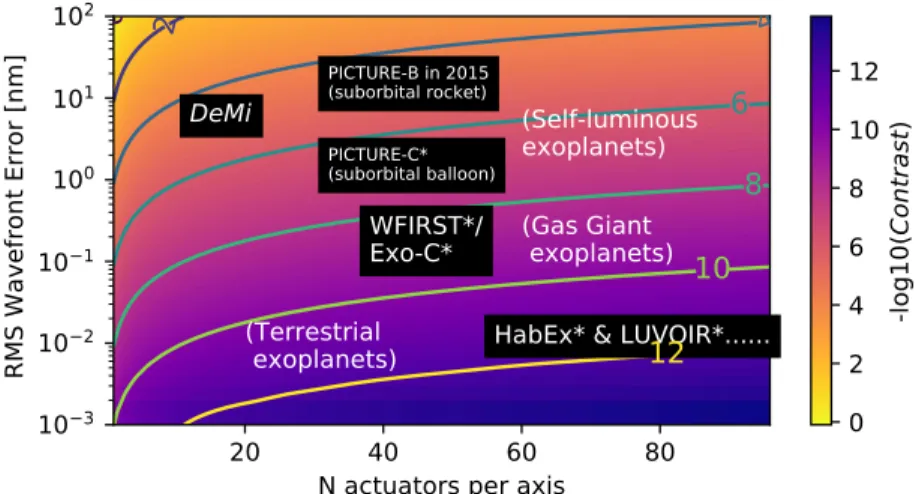
Figure 1: Cartoon heatmap of dark hole contrast with axes showing wavefront error versus the number of actuators across the mirror aperture at 633 nm. Payload marked with an asterisk are coronagraph designs which have yet to be flown. (The DeMi payload does not include a coronagraph).
Neglecting amplitude errors, a simple derivation of dark hole contrast (C) as a function of controlled root mean squared (RMS) wavefront error (hRM S) and the number of DM actuators across the pupil (N ), or the
number of spatial modes corrected, is given by Traub and Oppenheimer [9, equation 124]:
C = π ( 4hrms N λ ) (1)
The approximate performance of several missions are shown in Fig. 1 super-imposed upon a heatmap of log 10C for various values of N and hRM S, including two suborbital missions: the PICTURE10sounding rocket
flights of 2011 and 2015, which tested a 32x32 actuator microelectromechanical systems (MEMS) DM and the PICTURE-C balloon.11 Mission designs for imaging hot Jupiters and exozodiacal dust call for two 48×48 DMs,
such as the Wide-Field InfrarRed Survey Telescope (WFIRST) Coronagraph Instrument (CGI).12 The Exo-C
design similarly called for≥ 48 actuators across the telescope aperture.13 Further in the future, proposed missions
such as Habitable Exoplanet Imaging Mission (HabEx) and Large UV/Optical/Infrared Surveyor (LUVOIR) call for as many as 195 actuators across the telescope aperture.14
Deformable mirrors in space hold promise beyond exoplanet imaging; other applications include laser commu-nications,15, 16reconfigurable optical assemblies,17or deployable apertures.18 The DeMi payload will characterize
the performance of a MEMS deformable mirror in low earth orbit, decreasing the technological risk to future applications.
A 6U CubeSat bus19 provides sufficient power (approx. 20 watts), mass (approx. 4 kg), and volume (3U to
4U) for the relatively straightforward implementation of wavefront sensing and control with a MEMS DM. The Blue Canyon Technologies XB6 spacecraft bus has been selected to host the DeMi payload. The XB6 includes an XACT attitude determination and control system with a single startracker for sub-10 arcsecond pointing stability (1σ) in pitch and yaw.20 The following sections of this proceeding will focus on the optical and electrical design
of the DeMi payload and a brief discussion of possible astrophysical targets.
2. OPTICAL DESIGN
The primary objective of the DeMi mission is detailed characterization of a MEMS DM operation in space. In addition, the payload is designed to perform active wavefront correction in space, observe and correct stellar PSFs, and test wavefront retrieval and control algorithms.
The key component of the DeMi payload is the DM. A 140-actuator, continuous phase-sheet Boston Micro-machines (Cambridge, MA, USA) Multi-DM has been selected for its compact form factor and large stroke (1.5 to 5.5 microns surface displacement).
Both a Michelson interferometer and a Shack-Hartmann wavefront sensor21 were considered for DM
char-acterization in early DeMi designs.22, 23 As the DeMi design has evolved, a Shack-Hartmann sensor has been
selected as it allows measurement of wavefront errors of several microns without moving parts.24–26
Fig. 2a shows a top view of the payload ray trace. For astronomical observations, a telescope is formed by a 50 mm, f/4 off-axis parabola (OAP) primary mirror, which is focused on a field mirror, and a 12.7 mm, f/1.2 OAP which collimates the beam onto the DM. The primary OAP is under-filled by approximately 40% in order to fill the DM active aperture while minimizing vignetting and allowing use of off-the-shelf diamond turned parts. A single-mode optical fiber, embedded in the field mirror and fed by a laser diode, approximates a point source for internal calibration experiments. A 12.7mm, f/1.2 OAP collimates the beam onto the gold coated DM. After the DM, the corrected wavefront is split between an imaging camera and a pupil relay, which feeds the Shack-Hartmann Wavefront Sensor (SHWFS). A computer-aided-design rendering of the current payload design is shown in Fig. 3.
The telescope mirrors and optical bench are manufactured from aluminum, providing coefficient of thermal expansion (CTE) matching to minimize telescope thermal sensitivity. The less tham 5mW, approximately 635 nm, internal laser diode provides an alternative light source, decreasing risks and allowing measurements of the mirror surface without pointing requirements and with minimal photon noise compared to most astrophysical targets.
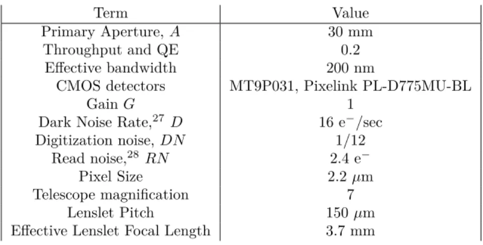
Table 1: Design optoelectrical properties. The effective quantum efficiency includes both detector sensitivity and optical losses. The nominal lenslet array is a Thorlabs MLA150M-5C.
Term Value
Primary Aperture, A 30 mm Throughput and QE 0.2
Effective bandwidth 200 nm
CMOS detectors MT9P031, Pixelink PL-D775MU-BL
Gain G 1
Dark Noise Rate,27 D 16 e−/sec
Digitization noise, DN 1/12 Read noise,28RN 2.4 e−
Pixel Size 2.2 µm Telescope magnification 7
Lenslet Pitch 150 µm Effective Lenslet Focal Length 3.7 mm
2.1 Wavefront Sensing Budget
In order to characterize a MEMS deformable mirror across its full stroke, a wavefront sensor (WFS) with large dynamic range is required. The classic SHWFS is limited at large wavefront tilts by confusion between spots outside the area of their respective lenslet and at small displacements by centroiding errors. The former limit is set by the lenslet pitch and focal length. The latter limit requires accurate modeling of centroid error. In order to characterize the sensitivity of the DeMi SHWFS, we develop semi-analytic and numerical models of centroid error.
Centroiding error arising from time dependent random processes, such as photon noise and detector noise, are estimated by propagation of uncertainty through a simple centroid model.29 We first estimate the
POPPY30“misc.airy_2d” function and astropy units.31 The total variance per pixel in the detector (x, y) plane
for time t is given by [29, Eq. 4.7]:
σ2(x, y, t) = RN2+ D× t + α(x, y) × t + DN (2) and the centroid error in the x-axis is given by [29, Eq. 4.9]:
σ<x>2 = ∑N i σ 2dx2 ∑N i σ2 (3)
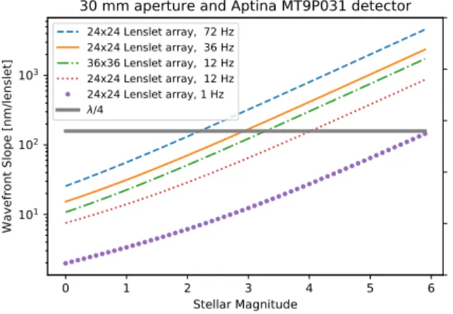
where dx is the distance between each pixel and the centroid, < x >. The mean centroid error versus V-band magnitude in both axes is shown in Fig. 4a for several temporal sampling rates. Select curves for 24×24 and
lenslet and 36×36 pupil sampling levels are also shown, illustrating the trade between wavefront precision and
spatial resolution in this photon limited regime.
The impact of quantum efficiency (QE) (or photo response non-uniformity (PRNU)) variation on centroiding will initially be corrected before launch via flat-field correction, but on-orbit radiation will alter pixel responsiv-ities. The impact on our detector was estimated numerically, first by measuring centroid of a PSF30 without
PRNU then applying quantum efficiency variations with increasing variation by increasing the standard devia-tion of a pixel sensitivity array with a mean of unity and a Gaussian distribudevia-tion. Fig. 4b shows the centroid error (left axis) and wavefront tilt error (right axis) versus increasing quantum efficiency. From left to right, dashed vertical lines show the un-irradiated, 0.5 krad(Si), 1 krad(Si), and 5 krad(Si) pixel-to-pixel variation for the chosen MT9P031 complementary metal-oxide-semiconductor (CMOS) detector.27 The centroid error is
inde-pendent of incident flux and will impact both laser and stellar observations. Thus, for the typical low-earth-orbit CubeSat radiation dose (< 1 krad/year),32the centroiding error will place a limit on the SHWFS sensitivity to
wavefront tilt per lenslet of 1 nm or lower.
2.2 Prototype Layout
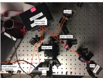
To understand and estimate the expected payload performance, we have begun component level testing and construction of a benchtop prototype. The most recent testing was done on the layout shown in Fig. 2b. The primary goal was to observe the operation of a deformable mirror and test the performance of the CMOS cameras and a commercial SHWFS.
With a refracting telescope providing collimated beam, main components in the optical setup are the laser, the large and small diamond turned OAPs, the DM, the beam splitter, the imaging detector, and the wavefront sensor. While the present payload design calls for a CMOS detector behind the SHWFS, initial testing of a 150 µm lenslet array was performed with a commercial CCD based SHWFS sensor (Thorlabs WFS150-5C). From initial testing of the WFS, the lowest observed standard deviation measurement in the wavefront was approximately 0.02 µm.
The WFS was also used to test the operation of the DM. We were able to observe the actuation of all points in the array and take measurements on the adjusted wavefront. Fig. 5 an example mean map and corresponding 1σ error map for two poked actuators, taken on an pneumatically isolated optical bench in the MIT Space Telecommunication, Astronomy and Radiation Lab.
3. ELECTRICAL DESIGN
The DeMi payload electrical system is responsible for reading out imaging and wavefront sensing cameras, controlling the deformable mirror, monitoring DM operation, and relaying data to the spacecraft bus. A block diagram of the payload is shown in Fig. 6. The design includes two cameras, two processors, two industrial grade SD cards for storage, the DM driver, a calibration laser and driver, and a heater. Note that spacecraft electrical functions including communication, attitude control, and power generation are handled by the XB6 bus. The electrical system and its interfaces to the optical system and XB6 bus are shown in the block diagram in Fig. 6.
£d5 Z'bT oipn}5oi;dp xemaZ ww og dsuiez8 sez$teso w.wnov 'avo oes 9 iei=1iu 0 vZ a
(a) Ray trace of the current payload optical design. Counter-clockwise from top right: a 50mm OAP, a flat field mirror for fiber injection, a 12.7mm collimating OAP, the deformable mirror, a beamsplitter sending light to the imaging camera (into the page) and a pupil relay and SHWFS.
(b) The laboratory optical setup used to prototype and test the integration of the optical components, cameras, and sensors.
Figure 2: Optical layouts.
Figure 3: Prototype payload optomechanical layout. Rendering of the preliminary payload mechanical layout (Credit A. Knoedler). Light enters horizontally from the top right through the conical baffle. The optical bench and telescope OAP mirrors will be fabricated from aluminum to minimize CTE mismatches. A 1U Cubesat structure (100 mm on a side) is shown at right for scale.
0 1 2 3 4 5 6 Stellar Magnitude
101
102
103
Wavefront Slope [nm/lenslet]
24x24 Lenslet array, 72 Hz 24x24 Lenslet array, 36 Hz 36x36 Lenslet array, 12 Hz 24x24 Lenslet array, 12 Hz 24x24 Lenslet array, 1 Hz /4
30 mm aperture and Aptina MT9P031 detector
(a) Predicted wavefront error versus V-band magni-tude for different exposure times and lenslet sampling intervals. 0.00 0.02 0.04 0.06 0.08 0.10 QE 104 103 102 101 100
centroid error [pix]
MT9P031 PRNU MT9P031 PRNU 0.5 krad(Si) MT9P031 PRNU 1 krad(Si) MT9P031 PRNU 5 krad(Si) 9e-04 9e-03 9e-02 9e-01 9e+00 9e+01
Wavefront Tilt [nm/lenslet]
(b) 100 curves of centroiding error (left axis) or wave-front tilt (right axis) versus the standard deviation of
pixel quantum efficiency ( σQE) for randomly
gener-ated sensitivity maps. Each iteration includes 20
inde-pendent maps of increasing σQE.
Figure 4: Wavefront sensitivity curves.
0.0
2.5
0
2
4
6
8
10
12
14
lenslets
Mean subregion
0.0
2.5
1 error
0.0
0.2
0.4
0.6
0.8
1.0
1.2
1.4
m
Figure 5: The mean wavefront and standard deviation of ten independent measurements with a commercial SHWFS after poking two edge actuators on the DM. The bottom actuator is a corner actuator and the upper actuator is central to the edge.
3.1 Command, Data Handling, and Communication
The payload computer is responsible for commanding the payload and processing the outputs of the two cameras. The selected flight computer is the Raspberry Pi Compute 3 module, a low cost and lightweight microprocessor produced by the Raspberry Pi Foundation. The Raspberry Pi runs Linux and has built-in SPI, USB and GPIO interfaces, providing all of the processing functionality necessary for the DeMi Payload. A Raspberry Pi is also planned for use as the flight computer on the Autonomous Assembly of a Reconfigurable Space Telescope (AAReST), a multi-CubeSat mission developed jointly by Caltech and the University of Surrey.17 Collected
Legend: Bus Computer Power Processing Unit 3.3 V UART SPI Camera 2 (WFS) USB Camera 1 (Imager) 2x Payload Computer 5V .4Lenslet Array 4-Lens 1 4-4111
El
41 GPIC GPIO GPIO Lens 2 Beamsplitter Calibration Laser Driver DM Driver F Heater DM 1 0.5" OAP -i 1 2" OAP 1 Mirrori
Calibration Laser DiodeFigure 6: A block diagram of the DeMi electroptical system. (Credit J. Figura)
data and the Raspberry Pi’s operating system will be stored on two industrial grade SD cards. Two Raspberry Pis and two SD cards will be flown to provide redundancy against a hardware failure. The two Raspberry Pi modules, SD cards, and supporting electronics will be mounted on a custom board.
The payload computer has four data interfaces: the two imagers are connected to the computer via USB, the DM driver is commanded with SPI, and the heater and calibration laser are controlled with GPIO interfaces to their respective drivers. Communication between the payload computer and the XB6 bus will be provided by a UART serial interface.
The XB6 bus will use two radios to communicate with the ground. The Cadet-U33is a software defined UHF
radio supplied by the Space Dynamics Laboratory, North Logan, UT. The Cadet can achieve 3 Mb/s downlink rate when communicating with Wallop Island’s UHF ground station. It is intended as the primary radio for science data. The Lithium-1 radio34 is produced by Astronautical Development (AstroDev), Ann Arbor, MI.
Lithium-1 operates at a data rate of 9.6 kb/s and will primarily be used for command, control and telemetry of the spacecraft.
During regular operations, frames from the camera are passed to the flight computer and processed to produce the relevant data products. These data products are stored on the SD cards until being passed to the bus to be downlinked or stored. A data budget is shown in Table 2. Three example data products are identified: the region of interest on the imager, the state of each actuator in the deformable mirror, and the centroids of the wavefront sensor. An example observation of five minutes of sampling at 12 frames per second is shown, and the storage margin is calculated for an 8 GB SD card with 2 GB reserved for the Pi’s operating system. The number of passes to downlink this observation is calculated using the Lithium or Cadet radios. The data budget shows that five minutes of observations take only 2.6% of the available storage, and can be downlinked in less than a second with the Cadet.
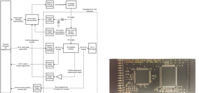
3.2 DM Driver
To actuate the DM, each channel must be supplied a variable voltage that can be as high as 250 V. A hardware driver must be used to generate these voltages. The existing Boston Micromachines D driver for the Multi-DM is 7 inches by 7 inches by 2.5 inches, far too large to fit in a CubeSat. Consequently, MIT is developing a miniaturized driver which repackages the Boston Micromachines driver architecture into a CubeSat form-factor. This size reduction is achieved by foregoing the Boston Micromachines driver’s large user-friendly connectors and cooling fans, as well as implementing high density circuit routing on the printed circuit boards. Additionally, the MIT driver differs from the Boston Micromachines driver by the addition of a separate current monitor for
Observation Data Produced
Data Product Dimensions Total Values Bits Total Bits (Mb)
Imager ROI DM Values WFS Centroid 128 x 128 12 x 12 48 x 48 Example Observation Duration Data / Sample Sample Rate Total Data Stored: Total Storage Storage Remaining 5 min 0.346 Mb 12 1246 Mb 48000 Mb 46754 Mb 16384 12 144 14 2304 64
Total Data per Sample:
0.197 0.002 0.147 0.346
Downlinking Example Observation Data Stored Averaging Compression Factor Data to Downlink 1245.6 Mb Every 10 frames 0.7 87.192 Mb Downlink Radio: Lithium Cadet Data Rate (Mb /s)
Pass Duration (min)
Passes to Downlink Example Observation 0.0096 10 3 10 15.1 0.05 e3-c. HV
IlEtl8 B°iver. Board, Nev. B.1
e e T.Eerialian NaY°1Y°es - x] nay. 103) e
.
° e .li::lüP.''.'d.'S:« _° e e1.
° ïá°171"117111111111NIIIIII°a P.t;
.¢à ° = .4;Sì erti-C'
3 ix-. JI er,= . so E.- .>i9
° ° cë °:
..ti..f 77!!'.. 111111MIg1111téWiW° 1 C e 111 :i A ° !' nan77 ^^^"'^`s
9119,11, -é'.-Table 2: Projected DeMi Data Budget, showing data products and an example observation.
each set of 32 high voltage outputs. Precise current monitoring will enable tracking of DM controller behavior and provide information to distinguish between possible DM actuator failures and controller malfunctions.
A schematic of the driver is shown in the left panel of Fig. 7. The driver consists of a high-voltage power supply and six pairs of digital-to-analog converters (DAC) and amplifiers. The high-voltage power supply steps up the voltages provided by the bus, and supplies that power to the amplifier. Each analog-to-digital converter is commanded by the payload computer over an SPI interface. Outputs of the DAC are fed into a high voltage amplifier, producing the desired output voltage. Each DAC and amplifier unit has 32 channels, and six pairs are used to control all 140 DM channels (52 channels are not used). A DAC/amplifier pair prototype is shown on the right panel of Fig. 7. It would suffice to have 5 DAC/amplifier pairs for a total of 160 channels. However, to decrease development time and risk while maintaining modularity, two identical boards with three DAC/amplifier pairs on each will be used (rather than two designs where one board has three DAC/amplifier pairs and another board only two).
Figure 7: The DeMi DM Driver. Left, a block diagram of the board design. Right, one populated unit consisting of an ADC and amplifier. (Credit C. Haughwout)
3.3 Power
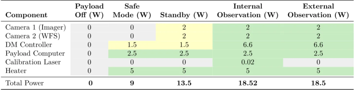
The bus handles power generation and storage, and provides 3.3 V and 5 V rails to the payload. Additional power processing for the calibration laser and the DM is handled by the laser driver and DM driver, respectively. A preliminary power budget, shown in Table 3, predicts that the payload will consume 18.1 W of power while operating. The budget shows the power consumption of each electrical component in each operational mode. Gray squares indicate that the component is off, yellow squares that the component is idle, and green squares that the component is operating nominally. The power consumption of the two cameras and the calibration laser is based on manufacturer specifications. Raspberry Pi numbers are based on estimates for the Pi with some functionality disabled. The DM driver’s power usage is estimated based on the power consumption of driver developed by NASA Ames for the larger BMC Kilo DM. The Ames driver controlled a 1024 channel DM, compared to DeMi’s 140 channel DM, and consumed 6.6 Watts during operation.35 This power number is used
as a conservative estimate for MIT’s DM driver. The heater is assumed to consume 5 Watts at all times, which may be revised downwards pending further thermal analysis. As development of the payload continues, the power budget will be updated with experimentally collected numbers.
Table 3: Projected DeMi power budget for four operating modes.
Payload Safe Internal External
Component Off (W) Mode (W) Standby (W) Observation (W) Observation (W)
Camera 1 (Imager) 0 0 2 2 2 Camera 2 (WFS) 0 0 2 2 2 DM Controller 0 1.5 1.5 6.6 6.6 Payload Computer 0 2.5 2.5 2.5 2.5 Calibration Laser 0 0 0 0.02 0 Heater 0 5 5 5 5 Total Power 0 9 13.5 18.52 18.5
4. TARGET SELECTION
4.1 Photometric Sensitivity
Five stars, of zeroth magnitude and brighter, Rigil Kentaurus (Alpha Centauri), Arcturus, Canopus, Sirius, and Vega are baselined for PSF and wavefront characterization. While the primary mission of the DeMi payload is DM characterization and despite a small aperture, as a telescope in space the DeMi payload provides a platform for recording precision photometric light curves of bright stars. A preliminary analysis using the parameters in Table 1 and neglecting PRNU variation predicts photometric sensitivity per orbit, at SNR=5, to one part in 3000 (a Neptune-like transit depth) around a Sunlike star brighter than V-mag of approximately 2.5. Low mass dwarf stars are preferable due to their high abundance and higher likelihood of transiting planet detection. (Evolved stars and early-type dwarfs have larger areas, which makes it more difficult to detect small planets.)
Potential target stars were found using the Exoplanet Catalog (ExoCat∗).36 We also prioritize stars in the
range 0.95M⊙ < M < 1.4M⊙and with a high metallicity, as they are more likely to host planets.37 For example,
five of the brightest promising transit targets with spectral types between F5 and M5 are shown in Table 4.
5. SUMMARY
This proceedings has provided a snapshot of the current design on the DeMi CubeSat payload. The CTE-matched all aluminum telescope and calibration laser provide redundant means of characterizing the DM surface. PRNU was not found to be a limiting factor in SHWFS sensitivity but stars which will provide diffraction limited surface measurements across each lenslet are limited to approximately second magnitude or brighter for the highest expected sampling rate (72 Hz). Fortunately, a number of candidate stars are available at or above
star name Distance (pc) V Band (mag) Spectral type Alpha Centauri 1.34 -0.01 G2.0V HIP 22449 8.07 3.17 F6V HIP 89937 8.06 3.56 F7Vvar HIP 27072 8.93 3.59 F7V HIP 78072 11.25 3.85 F6V
Table 4: Promising exoplanet transit stars identified from the ExoCat.
that brightness. A compact DM controller design has been prototyped and is expected to fit within the overall payload mass, volume, and power budgets. The DeMi payload is scheduled for fabrication in the Spring of 2018 with testing and integration with the XB6 bus in mid-2018.
6. FUTURE WORK
Before payload fabrication begins, the optomechanical design will be refined to survive the launch and orbit environments according to the NASA GEVS standard.38 In order to increase the precision of wavefront
mea-surements, and consequently DM surface knowledge, the wavefront sensing budget will be refined, and additional SHWFS retrieval algorithms will be implemented and tested along with a CMOS detector providing higher res-olution sampling of the spotfield. In addition to determining spatial sampling requirements, a control system model, including reaction wheel disturbances39 and wavefront measurement latency, is under development to set
temporal sampling requirements and the minimum stellar brightness required for the DM to maintain diffrac-tion limited pointing. The prototype DM driver board will be tested and the design will be extended to three DAC/amplifier pairs per board. The power budget will revised with measured component draws under realistic loads. Target selection will be refined by mission modeling in AGI System Tool Kit (Exton PA, USA) software package for a variety of orbits, constrained to those providing more than 1000 seconds of eclipse time and passing over the MIT UHF ground station in Cambridge, MA, USA.
ACKNOWLEDGMENTS
The authors would like to thank Anne Marinan of the Jet Propulsion Laboratory for support of this project and Eduardo Bendek and Ruslan Belikov, both of NASA Ames Research Center, for helpful discussions. Thanks also to John Taranto of Thorlabs, Inc., Jared Males of the University of Arizona, Jason Stewart of MIT Lincoln Laboratory, and Paul Bierden and Michael Feinberg of Boston Micromachines. A.A.K., J.N.G., and T.J.M. par-ticipated under the auspices of the Massachusetts Institute of Technology Undergraduate Research Opportunities Program.
This work has been sponsored by DARPA funding under a contract with Aurora Flight Sciences, Cambridge, MA, USA.
REFERENCES
[1] Bifano, T. G., Perreault, J., Mali, R. K., and Horenstein, M. N., “Microelectromechanical deformable mirrors,” IEEE Journal of Selected Topics in Quantum Electronics 5, 83–89 (Jan. 1999).
[2] Morzinski, K. M., Evans, J. W., Severson, S., Macintosh, B., Dillon, D., Gavel, D., Max, C., and Palmer, D., “Characterizing the potential of MEMS deformable mirrors for astronomical adaptive optics,” in [Proc
SPIE], 6272, 627221–627221–12 (2006).
[3] Doble, N., Yoon, G., Chen, L., Bierden, P., Singer, B., Olivier, S., and Williams, D. R., “Use of a micro-electromechanical mirror for adaptive optics in the human eye,” Optics letters 27(17), 1537–1539 (2002). [4] Scott, C., Potsaid, B., and Wen, J. T., “Wide Field Scanning Telescope Using MEMS Deformable Mirrors,”
International Journal of Optomechatronics 4, 285–305 (Aug. 2010).
[5] Rao, S. R., Wallace, J. K., Samuele, R., Chakrabarti, S., Cook, T., Hicks, B., Jung, P., Lane, B., Levine, B. M., Mendillo, C., Schmidtlin, E., Shao, M., and Stewart, J. B., “Path length control in a nulling coronagraph with a MEMS deformable mirror and a calibration interferometer,” in [Proc. SPIE ], 6888, 68880B–68880B (Feb. 2008).
[6] Siegler, N., “Exoplanet Exploration Program Technology Plan Appendix: 2016,” tech. rep., Jet Propulsion Laboratory (2016).
[7] Malbet, F., Yu, J. W., and Shao, M., “High-Dynamic-Range Imaging Using a Deformable Mirror for Space Coronography,” Publications of the Astronomical Society of the Pacific 107(710), 386–398 (1995).
[8] Pueyo, L., Kay, J., Kasdin, N. J., Groff, T., McElwain, M., Give’on, A., and Belikov, R., “Optimal dark hole generation via two deformable mirrors with stroke minimization,” Applied optics 48(32), 6296–6312 (2009).
[9] Traub, W. A. and Oppenheimer, B. R., “Direct imaging of exoplanets,” in [Exoplanets ], 111–156, University of Arizona Press, Tucson, AZ, USA (2010). Seager, S., ed.
[10] Douglas, E. S., Mendillo, C. B., Cook, T. A., and Chakrabarti, S., “Wavefront Sensing in Space from the PICTURE-B Sounding Rocket,” Proc. SPIE 9904-252 (2016).
[11] Cook, T., Cahoy, K., Chakrabarti, S., Douglas, E., Finn, S. C., Kuchner, M., Lewis, N., Marinan, A., Martel, J., Mawet, D., Mazin, B., Meeker, S. R., Mendillo, C., Serabyn, G., Stuchlik, D., and Swain, M., “Planetary Imaging Concept Testbed Using a Recoverable Experiment–Coronagraph (PICTURE C),” J.
Astron. Telesc. Instrum. Syst 1(4), 044001–044001 (2015).
[12] Sidick, E., Seo, B.-J., Marx, D., Poberezhskiy, I., and Nemati, B., “WFIRST / AFTA coronagraph contrast performance sensitivity studies: simulation versus experiment,” in [Proc. SPIE ], Navarro, R. and Burge, J. H., eds., 9912, 99126M (2016).
[13] EXO-C STDT., Chair, K. S. and EXO-C Design Team., Lead., F. D., [EXO-C Final Report- Imaging Nearby
Worlds], CL (2015).
[14] Morgan, R. and Siegler, N., “Initial look at the coronagraph technology gaps for direct imaging of exo-earths,” in [Proc. SPIE ], 9605, 96052I (Sept. 2015).
[15] Bifano, T., Schatzberg, L., Stewart, J., and Cornelissen, S., “MEMS Modulated Retroreflectors for Secure Optical Communication,” ASME International Mechanical Engineering Congress and Exposition.
Nano-Manufacturing Technology; and Micro and Nano Systems, Parts A and B Volume 13, 395–399 (Jan.
2008).
[16] Stewart, J. B., Murphy, D. V., Moores, J. D., Fletcher, A. S., and Bonneau, K. M., “Comparing adaptive optics approaches for NASA LCRD Ground Station #2,” in [Proc SPIE], Hemmati, H. and Boroson, D. M., eds., 8610, 86100M (2013).
[17] Underwood, C., Pellegrino, S., Lappas, V. J., Bridges, C. P., and Baker, J., “Using CubeSat/micro-satellite technology to demonstrate the Autonomous Assembly of a Reconfigurable Space Telescope (AAReST),”
Acta Astronautica 114, 112–122 (2015).
[18] Champagne, J., Hansen, S., Newswander, T., and Crowther, B., “CubeSat Image Resolution Capabilities with Deployable Optics and Current Imaging Technology,” in [AIAA/USU Conference on Small Satellites ], (2014).
[19] SLO, C. P., “6u CubeSat Design Specification Rev. PROVISIONAL,” (Apr. 2016).
[20] Mason, J., Baumgart, M., Woods, T., Hegel, D., Rogler, B., Stafford, G., Solomon, S., and Chamberlin, P., “MinXSS CubeSat On-Orbit Performance and the First Flight of the Blue Canyon Technologies XACT 3-axis ADCS,” in [AIAA/USU Conference on Small Satellites ], (2016).
[21] Platt, B. C. and Shack, R., “History and Principles of Shack-Hartmann Wavefront Sensing,” J Refract
Surg 17, S573–S577 (Sept. 2001).
[22] Cahoy, K. L., Marinan, A. D., Novak, B., Kerr, C., and Webber, M., “Wavefront control in space with MEMS deformable mirrors,” in [Proc SPIE ], 8617, 861708–861708–16 (2013).
[23] Cahoy, K. L., Marinan, A. D., Novak, B., Kerr, C., Nguyen, T., Webber, M., Falkenburg, G., Barg, A., Berry, K., Carlton, A., Belikov, R., and Bendek, E. A., “MEMS deformable mirror CubeSat testbed,” in [Proc SPIE ], 8864, 88640U–88640U–17 (2013).
[24] Marinan, A., Cahoy, K., Webber, M., Belikov, R., and Bendek, E., “Payload characterization for CubeSat demonstration of MEMS deformable mirrors,” in [Proc. SPIE ], 9148, 91483Z–91483Z–16 (2014).
[25] Marinan, A., Cahoy, K., Merk, J., Belikov, R., and Bendek, E., “Improving Nanosatellite Imaging with Adaptive Optics,” AIAA/USU Conference on Small Satellites (Aug. 2016).
[26] Marinan, A. D., Improving nanosatellite capabilities for atmospheric sounding and characterization, thesis, Massachusetts Institute of Technology (2016).
[27] Becker, H. N., Dolphin, M. D., Thorbourn, D. O., Alexander, J. W., and Salomon, P. M.,
[Commer-cial sensory survey radiation testing progress report], Pasadena, CA: Jet Propulsion Laboratory, National
Aeronautics and Space Administration (2008).
[28] Enright, J., Doug Sinclair, and Christy Fernando, “COTS Detectors for Nanosatellite Star Trackers: A Case Study,” DigitalCommons@USU, Utah State University (2011).
[29] Mendillo, C. B., Scattering properties of dust in Orion and the Epsilon Eridani exoplanetary system, PhD thesis, Boston University, Boston, MA, USA (2013).
[30] Perrin, M., Long, J., Douglas, E., Sivaramakrishnan, A., Slocum, C., and others, “POPPY: Physical Optics Propagation in PYthon,” Astrophysics Source Code Library , ascl:1602.018 (Feb. 2016).
[31] The Astropy Collaboration, Robitaille, T. P., Tollerud, E. J., Greenfield, P., Droettboom, M., Bray, E., Aldcroft, T., Davis, M., Ginsburg, A., Price-Whelan, A. M., Kerzendorf, W. E., Conley, A., Crighton, N., Barbary, K., Muna, D., Ferguson, H., Grollier, F., Parikh, M. M., Nair, P. H., Günther, H. M., Deil, C., Woillez, J., Conseil, S., Kramer, R., Turner, J. E. H., Singer, L., Fox, R., Weaver, B. A., Zabalza, V., Edwards, Z. I., Azalee Bostroem, K., Burke, D. J., Casey, A. R., Crawford, S. M., Dencheva, N., Ely, J., Jenness, T., Labrie, K., Lim, P. L., Pierfederici, F., Pontzen, A., Ptak, A., Refsdal, B., Servillat, M., and Streicher, O., “Astropy: A community Python package for astronomy,” Astronomy & Astrophysics 558, A33 (Oct. 2013).
[32] Day, C., “LEO Radiation, Its Effects on Electronics and Mitigation Approaches, A Primer,” in [CalPoly
CubeSat Developers Workshop], (2009).
[33] Kneller, E., Hyer, K., McIntyre, T., Jones, D., and Swenson, C., “Cadet: A High Data Rate Software Defined Radio for SmallSat Applications,” AIAA/USU Conference on Small Satellites (2012). [34] Astronautical Development, L., “Li-1 Radio User Manual Revision 0.4,” (Sept. 2009).
[35] Bendek, E., Lynch, D., Pluzhnik, E., Belikov, R., Klamm, B., Hyde, E., and Mumm, K., “Development of a miniaturized deformable mirror controller,” in [Proc SPIE], 9909, 990984–990984–12 (2016).
[36] Turnbull, M. C., “ExoCat-1: The Nearby Stellar Systems Catalog for Exoplanet Imaging Missions,” ArXiv
e-prints 1510, arXiv:1510.01731 (Oct. 2015).
[37] Fischer, D. A. and Valenti, J., “The Planet-Metallicity Correlation,” ApJ 622(2), 1102 (2005). [38] Milne, J. S. and Kaufman, D. S., “General Environmental Verification Specification,” (Jan. 2003).
[39] Shields, J., Pong, C., Lo, K., Jones, L., Mohan, S., Marom, C., McKinley, I., Wilson, W., and Andrade, L., “Characterization of CubeSat Reaction Wheel Assemblies,” Journal of Small Satellites 6(1), 565–580 (2017).