Design and Evaluation of an In-Pipe Leak Detection
Sensing Technique Based on Force Transduction
The MIT Faculty has made this article openly available.
Please share
how this access benefits you. Your story matters.
Citation
Chatzigeorgiou, Dimitris M., Rached Ben-Mansour, Atia E. Khalifa,
and Kamal Youcef-Toumi. “Design and Evaluation of an In-Pipe Leak
Detection Sensing Technique Based on Force Transduction.” Volume
4: Dynamics, Control and Uncertainty, Parts A and B (November 9,
2012).
As Published
http://dx.doi.org/10.1115/IMECE2012-87493
Publisher
American Society of Mechanical Engineers
Version
Final published version
Citable link
http://hdl.handle.net/1721.1/109110
Terms of Use
Article is made available in accordance with the publisher's
policy and may be subject to US copyright law. Please refer to the
publisher's site for terms of use.
DESIGN AND EVALUATION OF AN IN-PIPE LEAK DETECTION SENSING
TECHNIQUE BASED ON FORCE TRANSDUCTION
Dimitris M. Chatzigeorgiou∗ Mechatronics Research Laboratory Department of Mechanical Engineering
Massachusetts Institute of Technology Cambridge, MA 02139
{dchatzis@mit.edu}
Rached Ben-Mansour
Department of Mechanical Engineering King Fahd Univ. of Petroleum & Minerals
Dhahran, Saudi Arabia {rmansour@kfupm.edu.sa}
Atia E. Khalifa
Department of Mechanical Engineering King Fahd Univ. of Petroleum & Minerals
Dhahran, Saudi Arabia {akhalifa@kfupm.edu.sa}
Kamal Youcef-Toumi Mechatronics Research Laboratory Department of Mechanical Engineering
Massachusetts Institute of Technology Cambridge, MA 02139
{youcef@mit.edu}
ABSTRACT
Leakage is the major factor for unaccounted fluid losses in almost every pipe network. In most cases the deleterious effects associated with the occurrence of leaks may present serious eco-nomical and health problems and therefore, leaks must be quickly detected, located and repaired. The problem of leakage becomes even more serious when it is concerned with the vital supply of fresh water to the community. Leaking water pipelines can de-velop large health threats to people mostly because of the infiltra-tion of contaminants into the water network. Such possibilities of environmental health disasters have spurred research into the development of methods for pipeline leakage detection.
Most state of the art leak detection techniques have limited applicability, while some of them are not reliable enough and sometimes depend on user experience. Our goal in this work is to design and develop a reliable leak detection sensing system. The proposed technology utilizes the highly localized pressure gradi-ent in the vicinity of a small opening due to leakage in a
pressur-∗Please address all correspondence to this author.
ized pipeline. In this paper we study this local phenomenon in detail and try to understand it with the help of numerical simu-lations in leaking pipelines (CFD studies). Finally a new system for leak detection is presented.
The proposed system is designed in order to reduce the num-ber of sensing elements required for detection. The main concept and detailed design are laid out. A prototype is fabricated and presented as a proof of concept. The prototype is tested in a sim-ple experimental setup with artificial leakages for experimental evaluation. The sensing technique discussed in this work can be deployed in water, oil and gas pipelines without significant changes in the design, since the concepts remain the same in all cases.
INTRODUCTION
Leakage is the major factor for unaccounted water losses in almost every fluid distribution network worldwide; old or mod-ern. It is reasonable to claim that almost 15 to 25% of the total water production is lost to soil due to pipe leaks [1]. A study on
Proceedings of the ASME 2012 International Mechanical Engineering Congress & Exposition IMECE2012 November 9-15, 2012, Houston, Texas, USA
leakage assessment in Riyadh, Saudi Arabia shows the average leak percentage of the ten studied areas to rise up to 30% [2]. Losses through leaks represent a significant portion of the water supply, hence identification and elimination of leaks is imper-ative to efficient water resource management. Moreover, leaks in oil or gas pipes impose great environmental danger and also cause significant economic losses to the corresponding indus-tries.
Pipeline leak may result, for example, from bad workman-ship or from any destructive cause, due to sudden changes in pressure, corrosion, cracks, defects in pipes or lack of mainte-nance [3]. Thus, water authorities as well as gas and oil indus-tries have been paying serious attention in preventing the loss of their product due to leakages in the pipe network. Over the last 20 years significant amount of research has been performed towards the development of novel leak detection techniques.
Mays [4] and Hunaidi [5] report various techniques for leak detection. First, water losses can be estimated from audits. The difference between the amounts of fluid distributed by the util-ity and the total amount of fluid recorded by usage meters in-dicates the amount of lost fluid. Acoustic leak detection can also be normally used not only to identify but also locate leaks. Acoustic methods consist of listening rods or aquaphones. These devices make contact with valves and/or hydrants in water net-works. Acoustic techniques may also include geophones to listen for leaks on the ground directly above the pipes [5]. Chatzigeor-giou et. al. study the merits of an in-pipe acoustic leak detection sensor [6, 7] and propose the deployment of an in-pipe robot for leak detection [8].
More sophisticated techniques use acoustic correlation methods, where two sensors are placed on either side of the leak along a pipeline. The sensors bracket the leak and the time lag between the acoustic signals detected by the two sensors is used to identify and locate the leak [9]. Finally, several non-acoustic methods like infrared thermography, tracer gas technique and ground-penetrating radar (GPR) have been widely used for leak detection [10, 11]. Nevertheless, all state-of-the-art leak de-tection techniques have limitations and drawbacks in terms of reliability, scalability and cost.
Lately many robots have been developed for in-pipe inspec-tion and used to identify corrosion, cracks or normal wear and damage. State of the art robots are usually wheeled, camera car-rying and controlled via cables. Most of them are focused on oil or sewer-mains. One such robot was developed by Schempf at CMU [12] and was the untethered Explorer robot. The system is a long-range, leak-inspection robot, working in real-gas-pipeline conditions and is being controlled by an operator in real-time through wireless RF technology. The operator is constantly look-ing into a monitor as the robot is searchlook-ing for leaks visually via a camera.
Past experience has shown that in-pipe inspection is much more accurate, less sensitive to random events and external noise
and less subjective to the user’s experience. Moreover, pipe in-spection from the inside brings the ”sensing elements” closer to the leak source and consequently the system itself becomes ca-pable of pinpointing very small leaks in a reliable fashion. In general such systems face major challenges associated with com-munication, powering and are expensive to deploy.
In this work we study the phenomenon of the leaking pipeline and propose a novel in-pipe leak detection methodol-ogy. Our goal is to design and prototype a novel and reliable leak detection system with the minimum number of sensing el-ements. Additionally, the system needs to be able to operate and sense leakages completely autonomously. Moreover our proposed system will be deployable when the network is still operating, which means supply to the community is preserved during inspection unlike most current methods, e.g. oil pipe in-spection by wheeled robots and cameras is performed after pipes are drained. Finally, all concepts discussed in this work and the proposed methodology are applicable to all kinds of fluid pipes, namely water, oil and gas.
ANALYSIS
In this section we study the flow and pressure distribution inside a pipeline that is leaking. This is our first step towards understanding the phenomenon of a leaking pipeline and better support our proposed methodology in the coming sections. As it will be shown towards the end of this section, any leakage in a pipe is followed by a highly localized pressure jump (pressure gradient) happening very close to the opening. We are discussing this phenomenon throughout this work and try to utilize it in or-der to build a new and reliable leak sensing technique.
Pressure Gradient in the vicinity of a Leakage
For our analysis we consider the case of a straight pipe for simplicity. All results can be easily extended to bent sections, Y-and T-junctions Y-and other complicated pipe configurations with-out major changes. So, lets consider the case of a straight pres-surized pipe section as the one shown in the sketch of Fig.1. A planar sketch is presented here, although the real case extends in all three dimensions as a real pipeline does. Lets assume a leak-age exists in the middle of the pipe. As one would expect due to the difference in inside to outside pressure (∆p= pHigh− plow),
fluid is escaping from the pipeline through the opening. Notice that the longitudinal axis of the pipe is z, while the transverse is y.
In our work we focus on small leaks only. By this we mean small compared to the pipe dimensions (less than 10% of ID). This enables us to assume that the line pressure is almost con-stant across a leakage (in the longitudinal dimension), which is a reasonable assumption for small openings. Not to mention that large leaks can easily be detected by other means. For instance
Surrounding Medium Fluid Leakage Pipe
p
Lowp
Highy
z
FIGURE 1. A simple sketch of a leaking pipe. A leak occurs in the middle of the pipe and thus, fluid is escaping through the opening. No-tice the high line pressure, pHigh, and the low outside pressure, pLow.
installed pressure sensors around the network can easily sense the large drop in line pressure that such leaks impose to the net-work. Additionally a very large leak in a water pipe will be vis-ible even by pedestrians as water reaches the surface quickly. Thus, our goal is to develop a system able to sense small leaks and prevent them from growing into large leaks with potential great social damage.
The drop in pressure (pressure jump) ∆p as discussed before is occurring over a small distance close to leak opening. The pressure jump/gradient is a highly localized phenomenon in the vicinity of the leakage. Intuitively, we can guess that the volume of fluid that is affected by this phenomenon, namely this rapid local pressure gradient, depends on the fluid proper-ties (density ρ, dynamic viscosity µ) and the magnitude of the pressure difference ∆p.
Numerical Analysis of the Pressure Gradient near a Leakage
In this section we try to quantify and understand the phe-nomenon of the localized pressure gradient. More specifically we try to identify the size of the region that is affected by the pressure drop and understand what might be the optimal way to sense the leak.
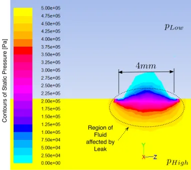
For our initial numerical study we assume the case of a dam-aged pipeline with a 4mm circular leak. This is a very special case but nevertheless will give results not much different than a more realistic scenario, e.g. an opening of random shape. For our analysis we consider a pipe with ID equal to 100mm, which happens to be a very common size in concurrent water distribu-tion networks. Pipes of such size exist in almost all modern water distribution networks in major cities around the globe.
We perform a CFD study on this three dimensional leaking pipe problem and we use water as our working medium. We also apply a line pressure of pHigh= 5bars and an outside pressure of
pLow= 0bars. This is an extreme case since 5bars is considered
a very high line pressure for water distribution networks but still
Region of Fluid affected by Leak
p
Lowp
High4mm
C o n to u rs o f St a ti c Pre ssu re [ Pa ]FIGURE 2. The static pressure distribution in the vicinity of the leak. A magnified version of a small leak is depicted. The fluid region as well as the surrounding medium are shown. The pipe material/wall is skipped on purpose. It is obvious that only a very small region of fluid is affected by the pressure drop. Contours of static pressure are shown in Pa.
remains a good value for an initial numerical study. Finally, for completeness we consider the case where water is also flowing with an average speed of 1m/s through the pipe. The direction of the ambient flow is from left to right towards the positive z-axis. As expected some of this fluid will escape the pipe through the opening.
Running a CFD case with the parameters specified above we get the pressure distribution shown in Fig.2. The image is zoomed in the region of interest, namely the vicinity of the 4mm opening. The localized drop in pressure is clearly depicted in this image. We observe from this figure that static pressure is dropping gradually from pHighto pLow. We observe that there is
a very small volume of fluid that is affected by this drop as shown in the figure.
From the CFD case we can extract the static pressure value for each point on the mesh. In Fig.3 we present the plots of the static pressure distribution along the z-direction for different heights y. The height here represents the normal distance from the leak. Thus, a height of y= 49 corresponds to a normal dis-tance of 1mm from the leak for a 100mm diameter pipe (radius is 50mm). Moreover z= 0 corresponds to the leak center location along the axis the symmetry of the pipe.
As one would expect the largest pressure jump occurs at z= 0. As one moves further downstream or upstream the
pres-−10 −8 −6 −4 −2 0 2 4 6 8 10 3.8 4 4.2 4.4 4.6 4.8 5
x 105 Static Pressure along z for various distances below the leak
z−distance from leak [mm] − Centered at leak location
Static Pressure [Pa]
1 mm 2 mm 3 mm 4 mm 5 mm 10 mm
FIGURE 3. The static pressure along the z-axis for various distances from the opening. Each curve corresponds to a different normal distance from the leak opening.
sure increases again in an almost symmetric fashion as expected. Not surprisingly we observe that the region/volume of fluid that is affected by this pressure gradient is very small. Approximately a leak diameter away from the leak (4mm) the drop has disap-peared and static pressure is back to pHigh= 5bars = 500.000Pa.
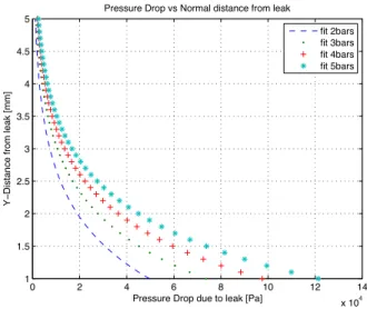
In the previous case we studied the case of a very high value of line pressure. By repeating the simulations for different val-ues of pressures we observe that the main trends and concepts remain the same in every case. In Fig.4 we summarize the re-sults for four different cases of lower line pressures. Those plots show the pressure drop at the leak location (z= 0) as the normal distance from the opening increases from 1mm to 5mm (moving away from the opening).
It is quite common between all cases that the pressure drop is almost 0 at a normal distance of 3.5 − 4mm from the leak open-ing. Nevertheless, it is clear that if the sensor is close enough (< 4mm) it will be able to pick this pressure drop and detect a potential leakage easily. The closer the sensor finds itself to the pipe walls, the larger the magnitude of the pressure drop and the easier the sensor will be able to detect the leakage. Of course though the effectiveness of such a sensor depends very much on its sensitivity but nonetheless it is clear that there is room here for creating a new sensing methodology by utilizing this local-ized pressure gradient.
The cases presented here included a leak opening of 4mm. We observe that although this corresponds to a very small leak our measured quantity, although very localized, is significantly large and thus, could potentially be sensed efficiently. In this work we will try to utilize the large pressure gradient to design and fabricate a reliable mechanical leak detection sensor based
0 2 4 6 8 10 12 14 x 104 1 1.5 2 2.5 3 3.5 4 4.5 5
Pressure Drop due to leak [Pa]
Y
−
Distance from leak [mm]
Pressure Drop vs Normal distance from leak
fit 2bars fit 3bars fit 4bars fit 5bars
FIGURE 4. ”Pressure Drop” for different values of line pressure pHigh. Notice that after passing the “limit” of 4mm of normal distance
from the leak opening the pressure has risen back to line pressure and the leak pressure drop is not sensible any more ( 0 Pressure Drop).
on force transduction. More details on the sensing methodology are discussed in the coming sections.
Repeating the cases for different sizes of leakages in similar pipes shows that although the values might change significantly, the trends and signatures remain the same in the pressure gradi-ent [13]. More importantly, the signature of the large pressure gradient in the vicinity of the leak is always present in pressur-ized pipes independent from the size, the working medium or the surrounding medium.
OVERVIEW OF THE SENSING SYSTEM
We showed in the previous sections that each leak in a pres-surized pipeline is accompanied by a highly localized pressure gradient. In this section we present a methodology that utilizes this very localized pressure gradient in an efficient way in order to sense leakages and provide information about the potential ex-istence and magnitude of leakages along pipelines.
A very simple sensing implementation would be the use of a series of pressure sensors (differential or absolute) around the circumference of the pipe. In this embodiment one would have to put the array of sensors very close to the pipe wall. Thus, the sys-tem would be able to sense this localized pressure drop all over the circumference of the pipe. Nevertheless, such an implemen-tation would be very costly and inefficient since it would include many sensors and significant amount of power to operate.
In order to minimize the number of sensing elements we can let a single body come very close to the opening. This body is then able to be displaced due to forces stemming from the
pres-Fluid
p
Lowp
Highy
z
A
F
Region of Fluid affected by LeakF
zFIGURE 5. A body that is close to the leak opening is subject to a force because of the difference in pressure. The body is pulled closer to the leak and the pipe wall as it is sucked in by the pressure gradient. The whole system is supposed to be moving at a constant speed along z (from left to right). The carrier mechanism is skipped on purpose.
sure gradient and the leakage. In other words, the concept in-cludes a system that is moving along the pipeline and a single body of this system is able to come close to a potential opening. This body is then displaced by the leak forces. This concept is presented in Fig.5. The system is supposed to be moving from left to right and the body, which is shown here as a small plate, is pulled upwards by the pressure gradient. This happens only if the plate comes close to the opening or if the body finds itself within the critical volume of fluid that is affected by the pressure gradient.
If the body has enough time to reach the wall it will touch the pipe wall and remain there. After this instant in time the force is equal to: F= A∆p, where A stands for the area of the leak opening and ∆p= pHigh− pLow. We need to mention here
that such a sensing body/system is moving inside the pipeline with the help of a carrier that could be an autonomous robot for instance. Details of the carrier are not discussed in this paper and a simple autonomous wheeled robot is used for experimentation later during this work.
The pulling force due to the pressure gradient will prove to be very useful in our leak detection methodology. A promising sensing approach would be to have some kind of either force or displacement sensors and thus be able to sense the movement of the body with respect to a fixed reference frame on the carrier.
Such an absolute radial/transversal displacement or force sensing technique would lead to false alarms very easily. In gen-eral, pipelines are not clean inside because of dirt, particles that sit on the bottom part and sometimes also due to corrosion. Af-ter some time of operation the effective diameAf-ter of a pipeline is not anymore equal to the nominal ID as it came off the factory. Sometimes the fluctuations in the ID can be very large. This said, such a sensor, that is based on the radial/transversal dis-placement of the body, would prove inefficient and unreliable. A small change in the diameter would push the body and ”trigger” a false alarm, as this motion would be captured by appropriate sensors. This implication naturally leads us to the next design
Fluid
p
Lowp
Highy
z
F
DrumF
zM
Flexible MaterialF
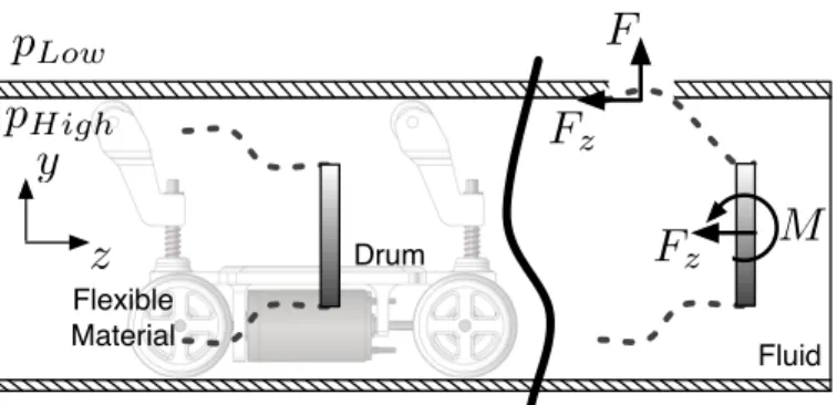
zFIGURE 6. The main concept is presented here. A drum is moving from left to right with the help of a carrier robot. The flexible material (dotted line) is sucked by the leak due to the pressure gradient. More-over, a friction force Fzis generated. As the carrier moves to the right
a force and torque are transferred to the drum and can be sensed by appropriate sensing elements one the drum/carrier.
concept.
Sensing Concept
Our proposed methodology consists of a flexible body that moves close the pipe wall. This flexible body embraces the cir-cumference of the pipe, finds itself within 2 − 3mm from the wall and also lets itself get displaced easily in case of a leak. Thus, almost any size of leak, small or large, will pull the flexible ma-terial towards the walls. This is more or less though dependent on the stiffness of the material, but we consider low stiffness ma-terials in this work, e.g. thin soft polyurethane or multi-purpose neoprene rubber sheets (membranes). Finally, when the material touches the wall a corresponding normal force F is generated. This force gets larger as the size of the opening increases (it de-pends linearly on the area of the opening A).
As the carrier moves constantly to the right (Fig.6) another force is generated. This force, Fz, is now apparent because of
friction between the flexible material and the pipe wall. A very significant portion of this friction force is due to the fact that the flexible material bends and confronts to the opening, making it more difficult to escape. When the flexible material detaches from the opening, as the carrier continues to move to the right, both forces disappear.
The flexible material is rigidly connected to the drum and the drum is allowed to move in specific directions. The modes cor-responding to those directions can be observed with appropriate selection and placement of sensors. In our proposed system we measure the forces on this drum directly. The force Fz is
trans-ferred from the flexible material to the drum along with a torque (Fig.6).
We can also mention at this point that one can potentially design and optimize the shape and stiffness of the flexible body. By this one may make it less sensitive to fluctuations in pipe
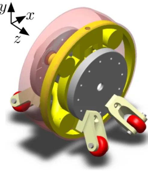
a
y
z
x
FIGURE 7. A 3D view of the proposed sensing system based on force transduction. The system is able to detect leaks anywhere around the circumference due to its ability to measure and sense longitudinal forces.
diameter and in general radial/transversal forces. Such a calibra-tion/optimization will eliminate false alarms and will reduce the sensitivity of the sensing system to random events. The only way the drum needs to be generating an ”alarm” is when there is a sig-nificant longitudinal force Fzthat the sensors may feel because of
the drum displacement.
Mechanical Design - Key Components
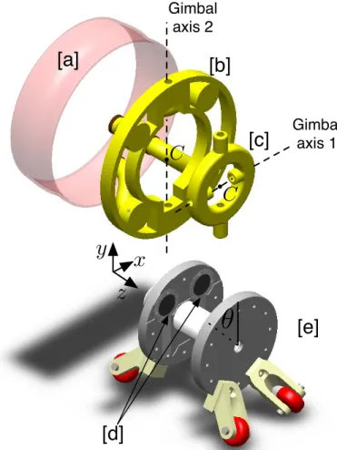
The proposed detailed design is presented in Fig.7. The sensing system is again supposed to be moving along the z−axis and sense any potential leakages at any angle θ around the cir-cumference.
More details are presented in Fig.8 and 9 along with expla-nations on the main components of the system. The drum is de-picted in yellow (solid color) and the flexible material in light red (transparent). The drum is suspended by a wheeled system and remains always in the middle of the pipe. A key fact with this proposed design is the gimbal mechanism consisting of dif-ferent parts (parts [b] and [c] in Fig.9). Because of the existence of this mechanism the drum is allowed to pivot about two axes and thus respond to a torque (generated by an equivalent friction force at some angle at the circumference of the pipe) about any axis passing through its center point C.
More specifically, whenever the flexible material is pulled towards a leak because of a pressure gradient, a normal force F is generated because of ∆p. As discussed before another force due to friction Fzis created. This force generates an equivalent force
and a torque on the drum and forces it to rotate about some axis passing through its center C. This pair of force and torque can then be sensed by appropriate force and/or displacement sensors
Moving Direction [a]
y
z
[b]C
FIGURE 8. The left view of the proposed design. The sensor is mov-ing to the right. Details: [a] Flexible material. [b] Drum.
mounted on the carrier.
In our proposed embodiment the sensors sit in the back plate of the carrier’s chassis. Those sensors are capable of detecting forces normal to their surface. As the drum tends to move, a force normal to those sensors is applied and thus a signal is generated on each one of them.
By using one sensing element only the system would be able to estimate the existence of a leak and could potentially trigger an alarm based on the magnitude of the generated signal. But by appropriate selection of the position of two or more sensors we can get full observability for the leak detection problem. This means that we can not only pinpoint the existence of a leakage as the system moves, but also estimate its magnitude and its po-sition/angle θleak around the circumference. To achieve full
ob-servability we need at least two sensors as used in Fig.9. Further discussion on this topic is outside the scope of this paper.
EXPERIMENTAL VALIDATION
In this section we present a prototype that we build as a proof-of-concept. Moreover we present initial experimental re-sults on leak sensing for evaluation and completeness.
Proof of Concept Prototype
In this section a prototype of the proposed design is pre-sented. More specifically we fabricated a first prototype of the sensing system in order to validate our design concept and test the sensing capabilities experimentally. All rigid parts were 3D printed using ABS material. For the flexible material we used thin sheets of flexible polyurethane that we attached around the circumference of the drum. The prototype is shown in Fig.10 where the assembled system is shown inside a 100mm ID pipe. The most critical part of the module, namely the gimbal mecha-nism, is shown in Fig.11.
[a]
[b]
[c]
[d]
[e]
Gimbal
axis 1
Gimbal
axis 2
✓
C
C
y
z
x
FIGURE 9. The exploded view of the proposed design. Notice how the angle θ is defined with respect to the vertical. All key components are visible. Details: [a] Flexible material, [b] Drum, [c] Gimbal part, [d] Sensors, [e] Carrier.
In this embodiment we installed the Force Sensing Resistors (FSR sensors) from Interlink Electronics as our sensing elements (force transducers). Moreover, we are using 2 separate sensors in order to get full observability as discussed in the previous sec-tion. Signals from the sensors are transmitted to the computer wirelessly with use of suitable RF modules and an ”Arduino Mini” microprocessor.
Experimental Results
In order to validate the design and evaluate our sensing sys-tem we test the syssys-tem in a simple experimental setup. In this case we present the results where the sensor will pass by con-secutive openings/leaks of 2mm in diameter. The line pressure during the experimentation is always constant and equal to 20psi (1.38bars). The working medium in this case is air (gas).
During experimentation we observe that the sensing system is able to capture signals that clearly indicate the existence of
FIGURE 10. A prototype of the proposed sensing system. The sys-tem is deployed inside a 100mm ID pipe in this case. The FSR sensors on the back circular plate are not visible in this configuration. The side view of the sensor system is shown on the right.
Gimbal
axis 1
Gimbal
axis 2
C
FIGURE 11. The gimbal mechanism at a random configuration. One can see the two axes of rotation. The flexible material is not presented in this photo and was later attached to the circumference of the drum.
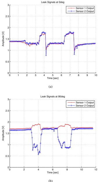
leaks. The initial results are indeed very promising. Signals cap-tured are presented in Fig.12 for two different cases. For those experiments the two sensors were placed on the back plate of the sensing systems along two vertical axes, i.e. off-center at 90o from each other. Sensor 1 is located at θ1= 45oand sensor 2 is
located at θ2= −45o.
In Fig.12(a) we present the signals captured by the two sen-sors when the system came across two similar leaks at an angle
θ= 0o. Whenever the system encounters a leak the response of the sensing elements and the force captured look similar. We can see that in this case the initial response of the signal to a leak is increasing in magnitude and when the flexible material detaches comes back to the dc value. This indicates that forces on both sensors are of pushing nature.
In Fig.12(b) we plot the signals captured by the two sensors when the system came across 2 similar leaks at an angle θ = 90oaround the circumference. Again the signals have the same
trends between leak instances. In this case the signals captured by the two sensors seem to be behaving in an opposite manner, namely as the one drops the other rises in magnitude at each leak. This indicates that force on sensor 1 is pushing, while force on sensor 2 is pulling.
The differences between the two experiments exist due to the fact that each leak is at a different angle and this results in a different pair of Fz and M about C as discussed in the previous
sections. Because the sensors are placed at different positions on the carrier’s back plate one can use estimation algorithms for inference of the position and the magnitude of the leaks. Never-theless, it is also pretty clear that whenever the system passes by a leakage, a clear change in signal(s) will easily pinpoint the existence of a leakage, either by using one or more than one sensors on the back plate..
CONCLUSIONS
In this work a novel and reliable leak detection system is presented and evaluated. The fundamental principle of a leaking pipe is studied numerically using CFD simulations and a new sensing concept is presented. The mechanical design is shown in this paper and a prototype is built and presented as a proof of concept.
The prototype is tested under real conditions in the lab. The system is able to pinpoint leakages along the pipeline. The re-sults presented in the last section of the paper seem to be very promising. More experimentation for careful calibration of the sensing parameters are now being carried out. This stage is cru-cial for accurate and reliable leak detection and for producing repeatable results.
Our future goals include the fabrication of even more proto-types and iterate the design for refinement. Moreover, some more experimentation is needed in order to evaluate the performance of the sensor under different conditions (pressure, flow, traveling speed, etc.). Finally, smart algorithms for the estimation of the position of the leak and its magnitude are under development. This will enable us to have a fully observable system, where leak magnitude and location will be able to be estimated via captured signals of two separate force/displacement sensors. Last but not least, we are planning to test our sensing system in other fluids, initially water but also oil and evaluate its performance there.
0 1 2 3 4 5 6 7 8 9 10 0 0.5 1 1.5 2 2.5 3
Leak Signals at 0deg
Time [sec] Amplitude [V] Sensor 1 Output Sensor 2 Output (a) 0 2 4 6 8 10 12 0 0.5 1 1.5 2 2.5
3 Leak Signals at 90deg
Time [sec]
Amplitude [V]
Sensor 1 Output Sensor 2 Output
(b)
FIGURE 12. Signals captured by the 2 FSR sensors during initial ex-periments. (a) Sensor runs across two leaks at an angle of θ = 0o. (b)
Sensor runs across two leaks at an angle of θ= 90o.
ACKNOWLEDGMENT
The authors would like to thank the King Fahd University of Petroleum and Minerals in Dhahran, Saudi Arabia, for funding the research reported in this paper through the Center for Clean Water and Clean Energy at MIT and KFUPM under Project Number R7-DMN-08.
Last but not least, the first author would like to thank the Onassis Public Benefit Foundation for the award of a prestigious scholarship throughout this work.
REFERENCES
[1] Vickers A. L. , 1999. “The future of water conservation: Challenges ahead”. Water Resources Update, Universities Council on Water Resources, 114, pp. 49–51.
[2] Al-Dhowalia K. H., Shammas N. Kh., Quraishi A. A. and Al-Muttair F. F., 1989. “Assessment of leakage in the Riyadh water distribution network”. First Progress Report, King Abdulaziz City for Science and Technology.
[3] Georgia Environmental Protection Division, Watershed Protection Branch, 2007. Water Leak Detection and Repair Program. EPD Guidance Document.
[4] Mays L., 2000. Water Distribution Systems Handbook. McGraw-Hill.
[5] Hunaidi O., Chu W., Wang A. and Guan W., 1999. “Leak detection method for plastic water distribution pipes”. Ad-vancing the Science of Water, Fort Lauderdale Technol-ogy Transfer Conference, AWWA Research Foundation, pp. 249–270.
[6] Khalifa A., Chatzigeorgiou D., Youcef-Toumi K., Khulief Y. and Ben-Mansour R., 2010. “Quantifying acoustic and pressure sensing for in-pipe leak detection”. ASME Inter-national Mechanical Engineering Congress & Exposition (IMECE2010).
[7] Chatzigeorgiou D., Khalifa A., Youcef-Toumi K. and Ben-Mansour R., 2011. “An in-pipe leak detection sensor: Sens-ing capabilities and evaluation”. ASME/IEEE International Conference on Mechatronic and Embedded Systems and Applications (MESA2011).
[8] Chatzigeorgiou D., Youcef-Toumi K., Khalifa A. and Ben-Mansour R., 2011. “Analysis and design of an in-pipe sys-tem for water leak detection”. ASME International Design Engineering Technical Conferences & Design Automation Conference (IDETC/DAC2011).
[9] Fuchs H. V. and Riehle R., 1991. “Ten years of experience with leak detection by acoustic signal analysis”. Applied Acoustics, 33, pp. 1–19.
[10] Hunaidi O., Chu W., Wang A. and Guan W., 2000. “De-tecting leaks in plastic pipes”. Journal - American Water Works Association, 92(2), pp. 82–94.
[11] Hunaidi O. and Giamou P., 1998. “Ground-penetrating radar for detection of leaks in buried plastic water distribu-tion pipes”. Seventh Internadistribu-tional Conference on Ground Penetrating Radar (GPR’98), pp. 783–786.
[12] Schempf H., Mutschler E., Goltsberg V., Skoptsov G., Gavaert A. and Vradis G., 2003. “Explorer: Untethered real-time gas main assessment robot system”. Proc. of Int. Workshop on Advances in Service Robotics (ASER). [13] Ben-Mansour R, M.A. Habib, A. Khalifa, K. Youcef-Toumi
and D. Chatzigeorgiou, 2012. “A computational fluid dy-namic simulation of small leaks in water pipelines for di-rect leak pressure transduction”. Computer and Fluids, p. doi:10.1016/j.compfluid.2011.12.016.