HAL Id: cea-02509252
https://hal-cea.archives-ouvertes.fr/cea-02509252
Submitted on 16 Mar 2020HAL is a multi-disciplinary open access archive for the deposit and dissemination of sci-entific research documents, whether they are pub-lished or not. The documents may come from teaching and research institutions in France or abroad, or from public or private research centers.
L’archive ouverte pluridisciplinaire HAL, est destinée au dépôt et à la diffusion de documents scientifiques de niveau recherche, publiés ou non, émanant des établissements d’enseignement et de recherche français ou étrangers, des laboratoires publics ou privés.
Plateau facility in support to ASTRID and the sfr
program: an overview of the first mock-up of the
ASTRID upper plenum, MICAS
D. Guenadou, I. Tkatschenko, P. Aubert
To cite this version:
D. Guenadou, I. Tkatschenko, P. Aubert. Plateau facility in support to ASTRID and the sfr pro-gram: an overview of the first mock-up of the ASTRID upper plenum, MICAS. NURETH16 - 16th International Topical Meeting on Nuclear Reactor Thermal Hydraulics, Aug 2015, Chicago, United States. �cea-02509252�
PLATEAU FACILITY IN SUPPORT TO ASTRID AND THE SFR
PROGRAM: AN OVERVIEW OF THE FIRST MOCK-UP OF THE
ASTRID UPPER PLENUM, MICAS
D. Guénadou, I. Tkatshenko and P. Aubert
CEA Cadarache, DEN/DTN/STCP/Core and Circuits Hydromechanics Laboratory (LHC) 13108 Saint Paul lez Durance - France
david.guenadou@cea.fr; isabelle.tkatschenko@cea.fr; philippe.aubert@cea.fr
ABSTRACT
The CEA and several industrial partners are involved in the development of a 4th generation reactor cooled by sodium, ASTRID (Advanced Sodium Technological Reactor for Industrial Demonstration). It is a 600MWe pool type reactor integrating cutting edge technologies.
Developments are in progress especially for the vessel and the apparatus. Experiments are needed for both validation of numerical codes and specific studies. In this way, a thermal-hydraulic loop, the PLATEAU facility, has been developed and built at the CEA Cadarache. Different mock-ups can be connected to this loop to study the different issues at various reactor conditions. Currently, 4 mock-ups are identified: the internal vessel, the entire pool reactor, the link between the external and the internal vessel, a part of the internal vessel at a higher scale to study specific issues.
The MICAS mock-up at 1/6 scale is dedicated to study the flow regime of the internal vessel (hot plenum), both for code validation and also engineering design development.
This mock-up has been built in transparent polymer to carry out some optical measurements as laser velocimetry. Numerical studies have been engaged to determine the general flow pattern in a way to identify the area of interest for detailed phenomenological studies.
KEYWORDS
Sodium, fast neutron reactor, mock-up, code validation
1. INTRODUCTION
ASTRID is a project of construction of a 4th generation reactor cooled by sodium. CEA is the leader of the project but it involves many partners (EDF, AREVA, BOUYGUES…). France has a large experience in SFR (Sodium Fast Reactor); it is why this coolant has been chosen. The design integrates this know-how and the feedback of the previous French SFR (Phoenix, Super-Phoenix) but also cutting edge
technologies. We are currently at the end on the preliminary design and new developments need to be validated. Experiments with sodium are rather complicated, mainly because of its high reactivity with water and its opacity. Part of the studies is performed on small scale mock-up using water. A hydraulic loop has been designed and built to welcome those mock-ups: PLATEAU. Depending on the issue, different similitudes are used. They are characterized by a dimensionless number, such as the Froude or the Richardson. Four mock-ups have been identified: the internal vessel, the entire pool reactor, the link between the external and the internal vessel, a part of the internal vessel at a higher scale to study specific issues. The first one to be studied will be the hot plenum: MICAS.
This article is dedicated to present the PLATEAU facility and the experimental program on the MICAS mock-up. In the first part, the ASTRID reactor concept is briefly presented. Then the PLATEAU experimental facility is descripted in detail. The issues of the internal vessel are summed-up and the
MICAS mock-up is presented. Then some numerical calculation results are showed to illustrate the flow in the internal vessel.
2. ASTRID REACTOR CONCEPT
ASTRID is a technological demonstrator reactor. The first aim of ASTRID (Advanced Sodium
Technological Reactor for Industrial Demonstration) is to demonstrate at a sufficient scale the technical options chosen, mainly in the field of the safety and the operability. It is a 600MWe pool reactor cooled by sodium. The main advantage of pool type reactor is to maintain the primary sodium in one main vessel. It reduces the risk of primary sodium leakage. The figure 1 is a sketch of the actual design. Detail presentations of ASTRID and the project are given in [1] and [2].
Figure 1. Cut view of the ASTRID primary circuit
France has a great experience in SFR. From the feedback of the French and international reactors, four main areas of progress have been identified:
• Improvement of the core efficiency and safety, especially concerning the prevention of severe accident [3];
• Prevention of the severe accident by the use of innovative systems such as decay heat removals;
• Reducing the risk of the interaction between sodium and water;
• Implement inspection and maintenance devices.
For qualifying the design options, and for validating the computations, experimental tests are needed [4] and [5]. For convenience, most experiments are carried out with water instead of sodium. The GISEH platform gathers all the hydraulic loops used for the qualification of the ASTRID components. The
PLATEAU (PLATeforme en EAU/water platform in French) facility, belonging to the GISEH platform, is dedicated to large components such as the vessels.
3. THE PLATEAU FACILITY
A sketch and a photo of the PLATEAU facility are presented respectively on the figure 2. This facility has to accommodate various mock-ups and must be the most versatile as possible. The entire circuits are shown on figure 3. The loop allows three injection points (named 1, 2 and 3 on figure 3) in the mock-up at different temperature and flow-rate. Without the utility networks (not drawn on figure 3), the
PLATEAU facility presents four main circuits (cf. figure 3):
• The main circuit (MCM in green on figure 3);
• The hot secondary circuit (HSC in red on figure 3);
• The cold secondary circuit (CSC in blue on figure 3);
• The transitory injection circuit (TIC in light blue on figure 3).
Figure 2. Global view and photo of the PLATEAU facility
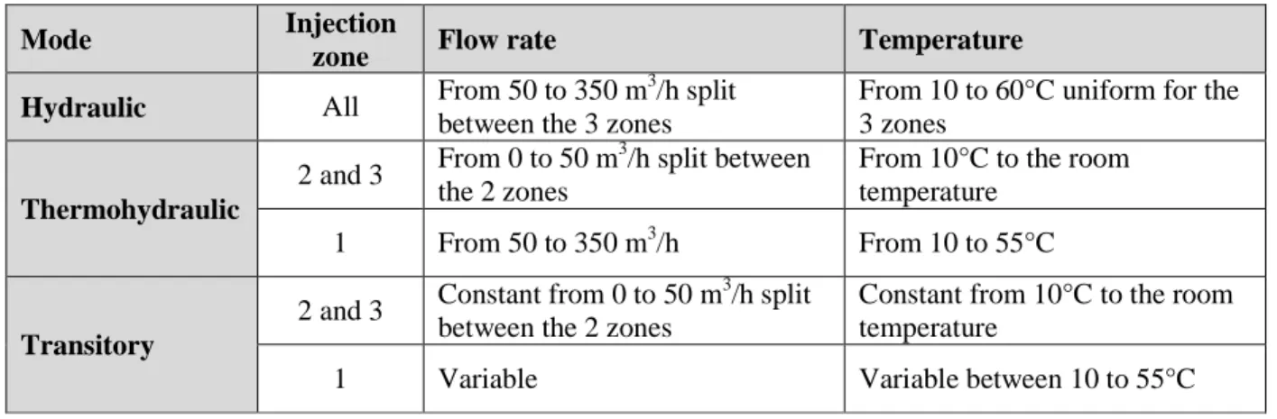
This network allows three operating methods:
• Hydraulic mode: only the MCM is used. The temperature is identical in the three injection points, but the flow rate is controlled independently for each one. The temperature is regulated by the mean of the heater HEAT01 and the exchanger EX01 linked to a cooling system.
• Thermohydraulic mode: the MCM, HSC and CSC are used. As in hydraulic mode, three different flow rates can be imposed on the injection points. But, this time two temperatures can be used; Outlet 1 (cf. fig. 3) with hot water and the two others with cold water. The HSC is used to heat by mixing to the setpoint temperature the water of the MCM; this latter is cooled in the mock-up by injection of cold water from the CSC. The heater HEAT01 cannot be used because the needed power to heat such flow rate is too high. As the level is the mock-up is kept steady, the water overflow is flushed to a tank (not shown on the figure3).
• Transitory mode: it is begun from the thermohydraulic mode and stabilized conditions. All the circuits are used (CIT, CSC, CHC, MCM). It aims at realize a temperature step (manly cold, but also hot) at the injection point 1 (cf. fig. 3). Water from TA01 (in case of hot step) or from TA02 (cold step) is injected downstream the pump P03. The temperature change rate is controlled by regulated valves.
Figure 3. Diagram of the PLATEAU hydraulic circuits
Table I. Operating ranges of the different modes of the PLATEAU facility
Mode Injection
zone Flow rate Temperature
Hydraulic All From 50 to 350 m
3 /h split between the 3 zones
From 10 to 60°C uniform for the 3 zones Thermohydraulic 2 and 3 From 0 to 50 m 3 /h split between the 2 zones
From 10°C to the room temperature
1 From 50 to 350 m3/h From 10 to 55°C
Transitory
2 and 3 Constant from 0 to 50 m 3
/h split between the 2 zones
Constant from 10°C to the room temperature
1 Variable Variable between 10 to 55°C
4. THE UPPER PLENUM MOCK-UP, MICAS
From the state of art of the previous mock-ups built in the 90s in the framework of the EFR program (European Fast Reactor), new needed experimental means has been listed for the ASTRID program. Several issues have been identified for the internal vessel and studies have to be carried on a reduce scale mock-up. The feedback cannot help to validate the innovative system implemented on ASTRID and calculations need validation data. Four main issues have been listed:
• Thermal interface behavior
It is created around the core due to the thermal losses of the internal vessel and the cold by-pass flow at the inlet of the core. In function of his location and moreover if it oscillates, it can damage the internal vessel by thermal fatigue.
• Free surface flow state
Mock-up TA01 TA02 E X 0 1 HEAT01 P01 P02 P03 MCM TIC CSC HSC 1 2 3
The oscillation of the surface flow can induce thermal oscillations on the immerged components (UCS, IHX…) and then damages due to thermal fatigue. Also, some gas can be carried though then IHX if vortexes are created at the surface. Gas getting into the inner core is proscribed.
• Thermohydraulic stability and flow distribution at the IHX inlet
At low reactor power, the hot jet coming from the core is raising rather than getting down. This behavior can introduce new thermal loads to the IHX and the other components immerged in the sodium.
• Thermal and flow pattern in the UCS.
Due to its location, just above the core, the UCS is exposed to high thermal stresses. The knowledge of the inside flow pattern at nominal and reduce reactor power is an essential data to characterize those thermal stresses.
The MICAS mock-up is dedicated to study these issues. A cross-view of this one is shown on the figure 4. Its scale is 1/6 of the ASTRID reactor and some geometrical simplifications have been carried out. For example, the hexagonal pipes in the core (fuel assemblies and related) have been replaced by cylindrical pipes. Nevertheless, the IHX are represented in detail because their geometrical configuration has a great impact on the flow pattern as the fluid is exiting the vessel. The opening height and width of the IHX outlet can be modified by adding tubes around the exit. It allows parametric studies. Due to its location just above the core, the UCS has a great influence on the flow pattern and that’s why its geometry in MICAS is highly detailed.
The flow distribution in the ASTRID core is quite complex. It would be difficult to reproduce it on the MICAS mock-up. It has been simplified into 3 zones. The injection room is show on the bottom of the figure 4; the central zone is corresponding to the core at high temperature (red zone on the figure 4); the intermediate one is related to the reflector; and the external zone is representing the internal fuel assembly storage. The two external zones flow at low temperature. Those 3 zones are connected to the PLATEAU facility (inlets 1 to 3 on the figure 4).
Figure 4. Cross view of the MICAS mock-up
IHX UCS Core P u m p p it
Concerning the measurements, the fluid temperature is measure by using PT100 stick (+/-0.1°C of accuracy). It allows the knowledge of the temperature at different depth versus the location. The bottom part of the internal vessel wall is equipped with PT100. It aims at characterize the thermal interface around the core.
Most of the components are built in transparent polymer for visualizations (high speed video) and measurements (laser Doppler velocity, particle imaging velocity). The mock-up is placed in an external vessel made of 12 plane walls to enhance the optical access. To increase the accessible laser domain, the pump pits include a plane face.
The flow-rate crossing the UCS is evaluated using 3 methods:
• By integrating the velocity field around the UCS outlet; the velocity field being determined by laser techniques.
• By measuring the difference of water level between each sheath and the internal vessel; an abacus of the pressure loss versus the flow-rate for each sheath has to be built.
• By introducing micro-fan flowmeter inside each sheath; this method is rather intrusive and has to be reserved to the large sheaths.
The gas entrainment is determined qualitatively and quantitatively. Rapid imaging focused on the IHX inlet helps to characterize if vortexes are absorbed into the IHX. For the whole IHX, the entrained gas volume has to be evaluated. A possible measurement technique to quantify the whole gas entrained is to introduce just before the P03 pump a liquid/gas separator. This solution is being studied
The inlet conditions of the MICAS mock-up experiments are calculated using the ASTRID reactor conditions in terms of flow-rate and temperature at nominal power. Depending on the study, different similitudes are used; concerning the free surface behavior, the Froude number is employed; for the thermal flow aspects, the Richardson number is used. We defined the dimensionless quantity X* by the ratio between the values of the mock-up and ASTRID: X*=Xmock-up/XASTRID
Then, for each type of study (hydraulic or thermohydraulic), the dimensionless numbers characterizing the flow (Re, We, Pe) can be calculated by setting Fr*=1 or Ri*=1. They are presented in the Table II where ρ is the density, L is the characteristic length, β is the thermal expansion, µ is the dynamic viscosity, α is the thermal diffusivity, σ is the surface tension and ∆T is the maximal temperature difference at the outlet core.
Table II. Dimensionless numbers depending on the study
Dimensionless number Hydraulic – Fr*=1 Thermohydraulic – Ri*=1
Re* √Fr∗ρ ∗L∗ . μ∗ 1 √Ri∗ β∗∆T∗ μ∗ L∗ . Pe* √Fr∗L ∗ . α∗ 1 √Ri∗ β∗∆T∗ α∗ L∗ . We* Fr∗ρ ∗L∗ σ∗ 1 Ri∗ ρ∗β∗ΔT∗ σ∗ L∗ . Q* √Fr∗L∗ . 1 √Ri∗ β∗ΔT∗L∗ .
The dimensionless physical properties (ratio between the water and the sodium properties) are presented in the table III. To calculate the sodium properties, we use the average outlet core temperature, 550°C. The water temperature is taken between 20°C and 60°C. In the Table III, L* is the scale of the MICAS
mock-up. According to Table III, we can calculate the characteristic numbers and the flow rate for each study. The flow-rate is calculated with the ASTRID data at nominal power.
For the hydraulic study, the characteristic numbers are shown in the Table IV depending on the mock-up water temperature. First on all, the flow-rate is independent from the temperature and is in the range of the P03 pump (cf. figure 3) of the PLATEAU facility. Concerning the dimensionless number, Re*, Pe* and We*, we notice they increase versus the water mock-up temperature. That means the similitude is more observed at high temperature and it’s better to carry out the experiments at 60°C.
The Table V shows the dimensionless numbers and the flow-rate for the thermohydraulic study. The temperature difference for the mock-up is set in function of the PLATEAU facility scope, i.e. 50°C. The water physical properties are calculated at the mean temperature at the inlet of the mock-up, i.e. 35°C. The flow-rate is in the range on the P03 pump (cf. figure 3) and is lower than in hydraulic. The Re* and the We* are close to the value in hydraulic.
Table III. Dimensionless physical properties in function of the water temperature.
T(°C) ρ* µ* Cp* β* σ* ∆T* α* L* 20 1.19 4.22 3.31 7.42x10⁻¹ 4.57x10⁻¹ 3.5x10⁻¹ 2.44x10⁻³ 1/6 35 1.19 3.03 3.31 1.23 4.47x10⁻¹ 2.51x10⁻³ 40 1.19 2.75 3.31 1.38 4.37x10⁻¹ 2.57x10⁻³ 60 1.18 1.96 3.31 1.85 4.16x10⁻¹ 2.68x10⁻³
Table IV. Dimensionless numbers and flow-rate depending on the temperature for the hydraulic study
T(°C) Re* Pe* We* Q (m3/h)
20 1.92x10⁻² 1.48x10⁻¹ 7.19x10⁻²
323
40 2.94x10⁻² 1.55x10⁻¹ 7.51x10⁻²
60 4.10x10⁻² 1.62x10⁻¹ 7.80x10⁻²
Table V. Dimensionless numbers and flow-rate for the thermohydraulic study
Re* Pe* We* Q (m3/h)
1.61x10⁻² 19.3 9.46x10⁻² 232
Those initial similarly analysis was useful to define the mock-up experimental parameters range
according the scale reduction. Moreover, CFD have been preceded on the MICAS geometry. They aim at understanding the flow pattern to place the instrumentation at the better location. The calculations have been realized using StarCCM+ v9 on a 13.4 million polyhedral cells mesh. The free surface is modeled by a symmetric condition; it assumes to be flat, the vortexes are not taking into account. Outlet pressure is put at the IHX. Inlet velocity conditions are set in the core location. The core ASTRID flow-rate distribution is observed. Those first calculations aim at studying thermohydraulic flows. The inner core temperature is set at 60°C and the outer at 10°C. The changes of the water physical properties (viscosity, density…) in function of the temperature are taking into account. The turbulence is modeled using the k-ε model. This article is not devoted to discuss about the whole study, some test case results are shown on the figure 5. It presents the velocity and the temperature fields in the internal vessel of MICAS for an equivalent reactor power of 100%.
Figure 5. Cut view of the velocity (left side) and the temperature (right side) field at Ri*=1.
On the figure 5 (left side), we can observe that the outgoing jet from the core is firstly impinging the UCS and then is deflecting down. This behavior is expected since the sodium calculations on the ASTRID reactor exhibit the same flow pattern. A part of the flow is crossing the UCS through the sheaths. 20% of the core flow-rate is coming into the UCS while only 11% is noticed in the ASTRID reactor; this
difference is due to not taking into account the pressure losses in the sheaths. Those latter are generated by in particular the control rod mechanisms. Calculations are in progress to take into account those pressure losses to correct the flow-rate crossing the UCS. Except around the IHX, the other part of the domain are quite dead zones with low velocity. Measurements have to be focused on the jet coming from the core and the flows around the UCS and the IHXs.
On the right side on the figure 5, the image shows that temperature field is quite homogeneous in the internal vessel. The temperature is close to 60°C in a great part of the domain. In particular the entire UCS is at 60°C. Only around the core, the temperature is near 10°C. It corresponds to non-fissile zone of the core. It creates high temperature gradient by the mixing of the cold and the hot jets. Instrumentation has to be adapted to this specific thermal pattern. The instrumental mesh has to be refined in this area. Another area of interest is at the bottom of the internal vessel. A thermal interface is developed at the outlet core elevation. Temperature sensors have been placed along the wall of the vessel to determine the location of this interface.
5. CONCLUSIONS
The ASTRID 4th generation reactor concept includes French and International feedbacks and main advances on the safety and operative point of view. New developments need to be validated. For some issues, numerical codes are not yet able to model correctly all the physical phenomena. Specific experiments have to be carried out, both to study the phenomenological issue and to feed a validation database for the codes. The GISEH platform has been designed in this way. The facilities of this platform use a simulant fluid, water, instead of sodium for convenience. The PLATEAU facility belonging to the GISEH platform is dedicated to study big components such as the vessels. It has been designed very
Temperature (°C) 10 60 Velocity (m/s) 0 0.7 UCS Core IHX
versatile to welcome mock-ups as numerous as possible. Many networks allow three injections in the mock-ups with different flow-rates and temperatures. The first mock-up tested on PLATEAU will be MICAS. It is a reduced scale of the ASTRID internal vessel built in transparent polymer for both visualization of the flow and laser velocimetry. This mock-up is equipped with various measurement apparatuses, such as stick of thermocouples, laser velocimetry. The different issues are studied using similitudes. The Froude number is used to study the free surface and vortices issues, and the Richardson number for the thermal flow instabilities. From those similitudes and the ASTRID data about the flow-rate and the temperature, operating conditions of MICAS are calculated. They are in the range of the ability of the PLATEAU facility. Some CFD calculations have been proceeded to determine the
measurement locations of interest. Concerning the velocity, measurements have to be emphasized around the core exit and the IHX. Focus has to be made at the bottom of the vessel and around the core for the temperatures.
REFERENCES
1. P. Le Coz, J.-F. Sauvage and J.-P. Serpantie, “Sodium-Cooled Fast Reactors: the ASTRID Plant Project”, Proceeding of ICAPP 2011, Nice, 2-6 May, (2011).
2. “4TH-Generation Sodium-Cooled Fast Reactors - The Astrid Technological Demonstrator”, http://www.cea.fr/content/download/131897/2449556/file/4th-generation-sodium-cooled-fast-reactors.pdf (2012).
3. P. Lo Pinto et al., “The Safety orientations during ASTRID conceptual design phase”, Proceeding of FR13, Paper CN-199-267, IAEA CN-199, Paris, France, (2013).
4. G. Rodriguez et al., “Development of experimental facility platform in support of the ASTRID program”, Proceeding of FR13, Paper CN-199-122, IAEA CN-199, Paris, France (2013).
5. O. Gastaldi et al., “Experimental platforms in support of the ASTRID program: Main experimental needs and devoted existing or planned facilities”, Proceeding of ICAPP 2015, Paper 15126, SFEN, Nice, France (2015).