Capillary-Limited Evaporation From
Well-Defined Microstructured Surfaces
The MIT Faculty has made this article openly available.
Please share
how this access benefits you. Your story matters.
Citation
Adera, Solomon, Rishi Raj, and Evelyn N. Wang. “Capillary-Limited
Evaporation From Well-Defined Microstructured Surfaces.” ASME
2013 4th International Conference on Micro/Nanoscale Heat and
Mass Transfer, 11-14 December, 2014, Hong Kong, China, ASME,
2014. © 2013 by ASME
As Published
http://dx.doi.org/10.1115/MNHMT2013-22120
Publisher
American Society of Mechanical Engineers
Version
Final published version
Citable link
http://hdl.handle.net/1721.1/120516
Terms of Use
Article is made available in accordance with the publisher's
policy and may be subject to US copyright law. Please refer to the
publisher's site for terms of use.
CAPILLARY-LIMITED EVAPORATION FROM WELL-DEFINED MICROSTRUCTURED
SURFACES
Solomon Adera1, Rishi Raj1,2, and Evelyn N. Wang1
1
Department of Mechanical Engineering Massachusetts Institute of Technology
Cambridge, MA, 02139 USA
2
Department of Mechanical Engineering Indian Institute of Technology
Patna, Bihar, India 800013
ABSTRACT
Thermal management is increasingly becoming a bottleneck for a variety of high power density applications such as integrated circuits, solar cells, microprocessors, and energy conversion devices. The performance and reliability of these devices are usually limited by the rate at which heat can be removed from the device footprint, which averages well above 100 W/cm2
(locally this heat flux can exceed 1000 W/cm2). State-of-the-art
air cooling strategies which utilize the sensible heat are insufficient at these large heat fluxes. As a result, novel thermal management solutions such as via thin-film evaporation that utilize the latent heat of vaporization of a fluid are needed. The high latent heat of vaporization associated with typical liquid-vapor phase change phenomena allows significant heat transfer with small temperature rise.
In this work, we demonstrate a promising thermal management approach where square arrays of cylindrical micropillar arrays are used for thin-film evaporation. The microstructures control the liquid film thickness and the associated thermal resistance in addition to maintaining a continuous liquid supply via the capillary pumping mechanism. When the capillary-induced liquid supply mechanism cannot deliver sufficient liquid for phase change heat transfer, the critical heat flux is reached and dryout occurs. This capillary limitation on thin-film evaporation was experimentally investigated by fabricating well-defined silicon micropillar arrays using standard contact photolithography and deep reactive ion etching. A thin film resistive heater and thermal sensors were integrated on the back side of the test sample using e-beam evaporation and acetone lift-off. The experiments were carried out in a controlled environmental chamber maintained at the water saturation pressure of ≈3.5 kPa and ≈25 °C. We demonstrated significantly higher heat dissipation capability in excess of 100 W/cm2. These preliminary results
suggest the potential of thin-film evaporation from
microstructured surfaces for advanced thermal management applications.
NOMENCLATURE
Symbols 𝐷 diameter (m) 𝐻 height (m) 𝐼 current (A) 𝐿 pitch (m) 𝑃 pressure (N/m2) 𝑄 heating power (W) 𝑞" heat flux (W/m2) 𝑅 resistance (Ω) 𝑇 temperature (K) 𝑡 time (s) 𝛥𝑇 superheat (𝛥𝑇 = 𝑇𝑤𝑎𝑙𝑙− 𝑇𝑠𝑎𝑡), (K) 𝑉 voltage (v) 𝑊 channel width (m) Subscripts 𝑎𝑚𝑏 ambient 𝑏𝑎𝑐𝑘 back side 𝑝𝑠 power source 𝑠𝑎𝑡 saturation ℎ𝑡𝑟 heater 𝑡𝑜𝑡 total𝑤𝑎𝑙𝑙 solid-liquid contact wall
INTRODUCTION
Advances in many cutting-edge-technologies are becoming increasingly dependent on the capability of removing concentrated heat loads from small areas. For example, early Intel Pentium CPUs utilized forced air convection to dissipate
Proceedings of the ASME 2013 4th International Conference on Micro/Nanoscale Heat and Mass Transfer MNHMT2013 December 11-14, 2013, Hong Kong, China
MNHMT2013-22120
≈30 W/cm2 waste heat. In the last few decades, this heat flux
has increased by more than threefold due to the ever-increasing miniaturization and faster processing speed [1-3] of electronic devices, which has motivated the need to develop more efficient thermal management schemes.
Two-phase cooling strategies have received significant interest due to the large latent heat of vaporization associated with phase change [4-6]. While various approaches such as pool boiling [7-9], flow boiling [10-13], spray cooling [14-16] and heat pipes [17-21] have been pursued by utilizing the latent heat of vaporization to improve thermal performance, thin-film evaporation [22-25] with liquid film thicknesses of few microns promises to be an efficient strategy for dissipating high heat fluxes. Schonberg and Wayner [26] developed an analytical model for predicting the maximum heat load that can be dissipated from the thin-film region. Wang et al. [24, 27] developed a simplified model based on the augmented Young-Laplace equation and obtained an analytical solution for the total heat transfer in the thin-film region. Their model showed that the thin-film region constitutes more than 50% of the total heat flux during evaporation. Yan et al. [28] showed that the heat transfer efficiency of thin-film evaporation is much higher than nucleate boiling heat transfer. In addition to the high heat fluxes, the superheat that is required for phase change in thin-film evaporation is expected to be smaller than that for a bubble growth during nucleate boiling, especially in the initial stages of bubble nucleation [28]. Ma and Peterson [29] numerically studied the thin film profile, heat transfer coefficient, and temperature profile along the axial direction of a triangular groove. Hanlon and Ma [30] showed that when the particles size decreases, the thin-film region can be significantly
increased. While all of these theoretical studies suggest the potential of thin-film evaporation, past experimental studies including using sintered metal powders [21, 31, 32], micro post arrays [33, 34], and carbon nanotubes [35, 36] for implementing thin-film evaporation indicate that limitations associated with transporting the coolant to the heated area exist. Recent studies have used micro/nanostructured surfaces to overcome this limitation by generating capillary pressure for passive liquid transport [37-40]. Nam et al. [41] have numerically characterized the capillary limitation of dense hydrophilic copper micropillar posts. Coso et al. [42] showed an enhancement in heat flux of ≈120 W/cm2 by using biporous
wicks (microscale pin fins separated by microchannels) to overcome the capillary limitation. Microscale fin pins are used to generate high capillary pressure while larger microchannels are used to reduce the overall flow resistance.
In this work, we used a two-tier strategy to overcome the capillary limitation. In the first-tier of surface texturing, we used closely spaced micropillar arrays to generate high capillary pressure, while a second-tier of surface texturing with sparse micropillars was used to create channels with minimal viscous loss for liquid transport. Such a strategy improves the liquid transport for thin-film evaporation by decoupling the capillary pressure from the viscous loss.
EXPERIMENT
We fabricated cylindrical silicon micropillar arrays in a square pattern with diameter D, height H and pitch L. Scanning electron micrographs (SEMs) of the textured area of two samples used in this investigation are shown in Fig. 1a and 1b.
Figure 1: (a) Scanning electron micrograph (SEM) of one level porosity sample # 1 with dimensions D, H, and L of 4.6 μm, 21.7 μm,
and 20.0 μm, respectively. (b) Scanning electron micrograph of biporous sample # 2 with dimensions D, H, and L of 7.7 μm, 24.2 μm, and 20.0 μm, respectively. The microchannel (second level of porosity) with width W=52.0 μm (edge-to-edge) was added to assist liquid transport by reducing the overall viscous loss. The arrows show the longitudinal direction of liquid transport. The SEM images were acquired at a 10˚ inclination. Side (c) and top (d) view of the schematic (not to scale) of a typical test sample used in the experiment. Degassed water was supplied to the water reservoir via a water hose. The capillary pressure that is generated as a result of microstructuring the surface transports the water from the reservoir to the 1x1 cm2 heated area.
The test samples were fabricated using projection photolithography and deep reactive ion etching (DRIE). For sample #1 in Fig. 1a, D, H, and L were 4.6 μm, 21.7 μm, and 20.0 μm, respectively. Biporous wicks with four longitudinal water channels of widths W=52.0 μm (edge-to-edge) were incorporated in sample # 2 where D, H, and L were 7.7 μm, 24.2 μm, and 20.0 μm, respectively (Fig. 1b). The biporous wicks were incorporated to assist liquid transport by reducing the overall flow resistance.
The overall dimensions of the test sample including the liquid reservoirs along the four edges was 3x3 cm2 while the
center 1x1 cm2 area was microstructured for thin-film
evaporation (Fig. 1c and 1d). The microstructured area was surrounded by a 8 mm wide water reservoir which was also created alongside the micropillars during the DRIE process. The depth of the water reservoir was assumed to be the same as the height of the micropillars as shown by the schematic in Fig. 1c. The reservoir was covered from the top using a 500 μm thick borosilicate pyrex glass which was bonded anodically to the silicon substrate by heating the silicon wafer and the pyrex glass to 400 °C. Prior to the anodic bonding, four 2.5 mm diameter holes were laser cut through the pyrex glass (Fig. 1d) for supplying water through a water hose. The back side of the test sample was patterned to create a resistive heater and three temperature sensors using e-beam evaporation and acetone lift-off. The heater covers the center 1x1 cm2 structured area. The
heater and sensors were fabricated using 100 nm thick platinum layer on top of a 20 nm thick titanium seed layer. They were annealed at 300 °C for 4 hours using a conventional oven. The sensors were calibrated before use and their resistance was confirmed to depend linearly on temperature with no hysteresis.
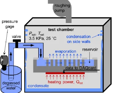
Figure 2: Schematic (not to scale) of the experimental setup.
The water in the canister is kept at the saturation temperature and pressure after degassing using a PID controller. The canister is kept at a higher temperature and pressure than the chamber which was also kept at saturated condition (≈3.5 kPa and ≈25 °C). This setup (the pressure difference between the
canister and the test chamber) allows liquid transport from the canister to the water reservoir. Data was acquired when the chamber reached steady state conditions where the rate of evaporation from the sample and the condensation on the side walls of the test chamber became equal. The condensate is collected at the bottom of the chamber through a manhole at the end of the experiment.
A DC power source (N5752A, Agilent Technologies) was used to supply the required heating power for evaporation. The heating power, heater resistance, back side temperature, and chamber saturation temperature and pressure were monitored and recorded using a LabView script and a data acquisition card (cDAQ-9174, National Instruments). A high speed camera (Phantom 7.1, Vision Research) was used to visualize the phenomena and identify the initiation of dryout.
Prior to each experiment, the samples were thoroughly cleaned with acetone, methanol, isopropanol (IPA) and deionized (DI) water. They were then dried with nitrogen gas followed by oxygen plasma treatment (Harrick Plasma) for 30 minutes to remove organic contaminants. The samples were then placed inside the test chamber while the liquid supply valve was fully closed, and vacuum was pulled to remove the non-condensable gasses from the system. A schematic (not to scale) of the test chamber and liquid supply system are shown in Fig. 2. The reagent grade DI water (CAS no. 7732-18-5, Sigma-Aldrich) in the canister is degassed in priori and kept at constant temperature and pressure using a PID (proportional-integral-derivative) controller. The canister is kept at a higher temperature and pressure than the test chamber which was kept at saturation condition (≈3.5 kPa and ≈25 °C). The pressure difference between the canister and the test chamber was utilized to transport the degassed water to the liquid reservoirs in the test sample. After removing the non-condensable gases from the system, the liquid supply valve was opened and the heater was turned on once a continuous liquid supply was established between the external water canister and the internal water reservoirs next to the micropillars. The capillary pressure then takes over as the mechanism to transport the liquid from the reservoir to the microstructured area which was heated using a platinum thin-film heater. The back side temperature is also measured using the temperature sensors which are integrated with the heater during the microfabrication step.
RESULTS
The result of a typical experimental run on sample # 1 with one level of micro-porosity and D=4.6 μm, H=21.7 μm, and L=20.0 μm is shown in Fig. 3. The input supply voltage to the back side heaters was increased in steps until dryout. The sample was maintained at each input power for a sufficiently large time confirming the steady state behavior at each step. The input voltage (Vps) as a function of elapsed time is shown in Fig. 3a
while the heater electrical resistance (Rhtr) is shown in Fig. 3b.
𝑄𝑡𝑜𝑡 = 𝑉𝑝𝑠𝐼𝑝𝑠, (1) where 𝐼𝑝𝑠 is the power supply current. The total heating power as a function of elapsed time is shown in Fig. 3c and the corresponding back side temperature 𝑇𝑏𝑎𝑐𝑘 along with the saturation chamber temperature 𝑇𝑠𝑎𝑡 is shown in Fig. 3d.
Dryout is observed at a critical power of ≈78W (t ≈28 min., Fig. 3c) beyond which the capillary-induced liquid supply mechanism was not sufficient to provide enough liquid for phase change heat transfer via evaporation. Dryout was also visually confirmed where a dry patch was observed to develop at the center of the heated area. The thermal runaway phenomenon where the sudden decrease in heat removal capability due to dryout resulted in a significant increase in the back side temperature was observed at t ≈28 min. in Fig. 3d. As a result of the increase in temperature, the heater resistance
rapidly increased (Fig. 3b) decreasing the current flow and hence the input power to the heater as shown in Fig. 3c. In order to avoid heater burnout and sample failure, the input power to the sample was cut off once the back side temperature exceeded 150 °C. The results presented in Fig. 3 were highly repeatable and similar values of dryout power were consistently observed during all experimental test runs. The onset of isolated nucleate boiling with localized regions of cyclic bubble nucleation, growth, departure, and rewetting processes were observed at larger superheats (ΔT>45 °C) which resulted in significant increase in the back side temperature fluctuation at higher superheats as shown in Fig. 3d. As a result, the error bars at higher superheats in Fig. 4 were significantly larger than those at lower superheats where the sample was undergoing predominantly thin-film evaporation based heat dissipation mechanism.
Figure 3: A typical experimental result for sample #1 where D=4.6 μm, H=21.7 μm, and L=20.0 μm. (a) Heater supply voltage, (b)
heater resistance, (c) total input heating power, and (d) back side and saturation/chamber temperature as a function of time. The voltage input was increased in steps until dryout at 110 v was observed. All parameters were recorded and monitored during the experiment. The total input heating power was calculated from the power supply voltage and current as given by Eqn. (1). At dryout, the thermal runaway phenomenon (d) was observed due to significantly small convective heat transfer coefficient. As a result of the sudden increase in temperature during dryout, the heater resistance rapidly increased (b), decreasing the input heating power (c). To avoid heater burnout and sample failure, the power input to the heater was shut off once the back side temperature exceeded 150 °C.
A dryout power of 78 W translates approximately to dryout heat flux of 78 W/cm2 for the 1x1 cm2 heated textured area in
the current case. The heat flux is plotted as a function of superheat in Fig. 4. A value of 78 W/cm2 is a significantly high
heat flux and demonstrates the potential of thin-film evaporation for advanced thermal management strategies using
a completely passive capillary pumping scheme. We performed additional experiments with another sample (#2) where the pillar diameter was increased to 7.7 μm while maintaining the height and pitch approximately the same. An increase in pillar diameter for the same pitch implies higher capillarity based pumping pressure as demonstrated in our previous work [40].
Alongside the increase in diameter, we also introduced longitudinal microchannels (second level of porosity) on sample #2. As a result, viscous losses in the micropillar array where the liquid had to travel uniformly through the micropillar array structure to reach the center of the sample further away from the reservoir were minimized due to these bypass liquid lines. The heat flux versus superheat for this sample is also shown in Fig. 4. As expected, significant increase (≈30%) in dryout heat flux (≈102 W/cm2) was observed on this sample
when compared to sample #1 (≈78 W/cm2). Moreover, the heat
flux for a given superheat, i.e. the effective heat transfer coefficient was also increased in sample #2 when compared to sample #1. This result can be explained by the reduction in the thermal resistance in the porous layer where the pillar diameter was increased from 4.6 μm to 7.7 μm. Isolated nucleate boiling was also observed at higher superheats (ΔT > 45 °C) for both samples which made it difficult to identify the contribution of thin-film evaporation to the heat dissipation mechanism. Moreover, due to the large test sample size (3x3 cm2) compared
to the heated area (1x1 cm2), the conduction and convection
losses were not accounted for in this calculation. We are currently working to improve the experimental setup to quantify the heat losses and more systematically investigate the parametric effect of the micropillar array geometry and microchannel width on the dryout heat flux. Nonetheless, the results obtained thus far are encouraging and show that thin-film evaporation is a promising approach to address thermal management needs of the next generation electronic devices.
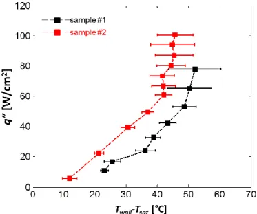
Figure 4: Heat flux as a function of superheat for two test
samples. Sample #1 has dimensions D=4.6 μm, H=21.7 μm, and L=20.0 μm. Sample #2 has dimensions D=7.7 μm, H=24.2 μm, and L=20.0 μm and contains longitudinal bypass microchannels of width 52.0 μm (edge-to-edge) to reduce the overall flow resistance to the liquid transport. Higher dryout heat flux and heat transfer coefficient were observed for the sample with two level of porosity (sample #2).
CONCLUSIONS
We investigated thin-film evaporation using well-defined two-tier microstructured surfaces. The first two-tier contains closely spaced micropillar arrays to generate high capillary pressure, while the second tier contains sparse micropillar arrays to create biporous wicks with microchannels for reducing the overall flow resistance. The microchannels improve liquid transport by providing a less-viscous bypass path for fluid flow. Preliminary experimental results indicate that thin-film evaporation is a promising thermal management strategy to address high heat fluxes in excess of 100 W/cm2. We dissipated
a heat flux of ≈78 W/cm2 by using micropillar array structures
only. By adding a second tier of biporous wicks into the design, we improved the dissipated heat flux to ≈102 W/cm2 (≈30 %
increase). The biporous wick enhanced the thermal performance by improving liquid transport to sustain evaporation and effectively delay dryout. The results presented in this work are preliminary and neither the micropillar array geometry nor the widths of the microchannels have been optimized to demonstrate the true potential of thin-film evaporation. However, we believe that higher heat flux can be dissipated by optimizing the geometry of the pillar array structure and the microchannel width.
ACKNOWLEDGMENTS
This material is based upon work supported by the National Science Foundation Graduate Research Fellowship Program under Grant No. 1122374. The authors gratefully acknowledge funding support from Office of Naval Research (ONR) with Mark Spector as program manager and the SMART program. The authors would also like to acknowledge the MIT Microsystems Technology Laboratory for fabrication staff support and use of equipment. S.A. acknowledges support from the National Science Foundation Graduate Research Fellowship Program (GRFP), and R.R. acknowledges support from Battelle’s National Security Global Business.
REFERENCES
[1] Mahajan, R., Chiu, C.-p., and Chrysler, G., 2006, "Cooling a microprocessor chip," Proc. IEEE, 94(8), pp. 1476-1486. [2] Majumdar, A., 2009, "Thermoelectric devices: helping chips to keep their cool," Nature Nanotechnology, 4(4), pp. 214-215. [3] Pop, E., Sinha, S., and Goodson, K. E., 2006, "Heat generation and transport in nanometer-scale transistors," Proc. IEEE, 94(8), pp. 1587-1601.
[4] Mudawar, I., 2001, "Assessment of high-heat-flux thermal management schemes," IEEE Transactions on Components and Packaging Technologies, 24(2), pp. 122-141.
[5] Qu, W., and Mudawar, I., 2002, "Prediction and measurement of incipient boiling heat flux in micro-channel heat sinks," Int. J. Heat Mass Trans., 45(19), pp. 3933-3945.
[6] Mills, A. F., and Mills, A., 1999, Basic heat and mass transfer, Prentice hall Upper Saddler River, NJ.
[7] Gaertner, R., 1965, "Photographic study of nucleate pool boiling on a horizontal surface," J. Heat Trans., 87, pp. 17-29. [8] Wang, C., and Dhir, V., 1993, "Effect of surface wettability on active nucleation site density during pool boiling of water on a vertical surface," J. Heat Trans., 115(3), pp. 659-669.
[9] Judd, R., and Hwang, K., 1976, "Comprehensive model for nucleate pool boiling heat transfer including microlayer evaporation," J. Heat Trans., 98(4), pp. 623-629.
[10] Gungor, K., and Winterton, R., 1986, "A general correlation for flow boiling in tubes and annuli," Int. J. Heat Mass Trans., 29(3), pp. 351-358.
[11] Kandlikar, S. G., 1990, "A general correlation for saturated two-phase flow boiling heat transfer inside horizontal and vertical tubes," J.f Heat Trans., 112(1), pp. 219-228.
[12] Kandlikar, S. G., 2002, "Fundamental issues related to flow boiling in minichannels and microchannels," Experimental Thermal and Fluid Science, 26(2), pp. 389-407.
[13] Liu, Z., and Winterton, R., 1991, "A general correlation for saturated and subcooled flow boiling in tubes and annuli, based on a nucleate pool boiling equation," Int. J. Heat Mass Trans., 34(11), pp. 2759-2766.
[14] Pais, M., Chow, L., and Mahefkey, E., 1992, "Surface roughness and its effects on the heat transfer mechanism in spray cooling," ASME Transactions J. Heat Trans., 114, pp. 211-219.
[15] Tilton, D. E., and Tilton, C. L., 1993, "High heat flux evaporative spray cooling," Google Patents.
[16] Mudawar, I., and Estes, K., 1996, "Optimizing and predicting CHF in spray cooling of a square surface," Journal of Heat Transfer, 118(3), pp. 672-679.
[17] Babin, B., Peterson, G., and Wu, D., 1990, "Steady-state modeling and testing of a micro heat pipe," ASME Transaction J. Heat Trans., 112(3), pp. 595-601.
[18] Peterson, G., 1994, An introduction to heat pipes: modeling, testing, and applications, John Wiley & Sons, Inc., New York.
[19] Peterson, G., and Ma, H., 1996, "Theoretical analysis of the maximum heat transport in triangular grooves: a study of idealized micro heat pipes," J. Heat Trans., 118(3), pp. 731-739. [20] Khrustalev, D., and Faghri, A., 1995, "Heat transfer in the inverted meniscus type evaporator at high heat fluxes," Int. J. Heat Mass Trans., 38(16), pp. 3091-3101.
[21] Jones, W. K., Liu, Y., and Gao, M., 2003, "Micro heat pipes in low temperature cofire ceramic (LTCC) substrates," IEEE Transactions on Components and Packaging Technologies, 26(1), pp. 110-115.
[22] Potash, M., and Wayner, P., 1972, "Evaporation from a two-dimensional extended meniscus," Int. J. Heat Mass Trans., 15(10), pp. 1851-1863.
[23] Wayner, P., Kao, Y., and LaCroix, L., 1976, "The interline heat-transfer coefficient of an evaporating wetting film," Int. J. Heat Mass Trans., 19(5), pp. 487-492.
[24] Wang, H., Garimella, S. V., and Murthy, J. Y., 2008, "An analytical solution for the total heat transfer in the thin-film
region of an evaporating meniscus," Int. J. Heat Mass Trans., 51(25), pp. 6317-6322.
[25] Ranjan, R., Murthy, J. Y., and Garimella, S. V., 2009, "Analysis of the wicking and thin-film evaporation characteristics of microstructures," J. Heat Trans., 131, p. 101001.
[26] Schonberg, J., and Ayner, P., 1992, "Analytical solution for the integral contact line evaporative heat sink," J. Thermophys. Heat Trans., 6(1), pp. 128-134.
[27] Wang, H., Garimella, S. V., and Murthy, J. Y., 2007, "Characteristics of an evaporating thin film in a microchannel," Int. J. Heat Mass Trans., 50(19), pp. 3933-3942.
[28] Yan, C., and Ma, H. B., 2013, "Analytical solutions of heat transfer and film thickness in thin-film evaporation," J. Heat Trans., 135(3), pp. 031501-031501.
[29] Ma, H., and Peterson, G., 1997, "Temperature variation and heat transfer in triangular grooves with an evaporating film," J. Thermophys. Heat Trans., 11(1), pp. 90-97.
[30] Hanlon, M., and Ma, H., 2003, "Evaporation heat transfer in sintered porous media," ASME Transactions J. Heat Trans., 125(4), pp. 644-652.
[31] Semenic, T., and Catton, I., 2009, "Experimental study of biporous wicks for high heat flux applications," Int. J. Heat Mass Trans., 52(21), pp. 5113-5121.
[32] Cao, X., Cheng, P., and Zhao, T., 2002, "Experimental study of evaporative heat transfer in sintered copper bidispersed wick structures," J. Thermophys. Heat Trans., 16(4), pp. 547-552.
[33] Ding, C., Bogorzi, P., Srivastava, N., Sigurdson, M., Meinhart, C., and MacDonald, N., "Super wetting of micro & nano structured titania surfaces," Proc. Transducers Int. Solid-State Sensors, Actuators and Microsystems Conf. , IEEE, pp. 401-404.
[34] Ding, C., Soni, G., Bozorgi, P., Piorek, B. D., Meinhart, C. D., and MacDonald, N. C., 2010, "A flat heat pipe architecture based on nanostructured titania," J. Microelectromech. Syst., 19(4), pp. 878-884.
[35] Weibel, J. A., Garimella, S. V., Murthy, J. Y., and Altman, D. H., 2011, "Design of integrated nanostructured wicks for high-performance vapor chambers," IEEE Transactions on Components, Packaging and Manufacturing Technology, 1(6), pp. 859-867.
[36] Kim, S. S., Weibel, J. A., Fisher, T. S., and Garimella, S. V., "Thermal performance of carbon nanotube enhanced vapor chamber wicks," Proc. 14th Int. Heat Trans. Conf., ASME. [37] Sangani, A., and Acrivos, A., 1982, "Slow flow past periodic arrays of cylinders with application to heat transfer," Int. J. Multiphase Flow, 8(3), pp. 193-206.
[38] Ishino, C., Reyssat, M., Reyssat, E., Okumura, K., and Quéré, D., 2007, "Wicking within forests of micropillars," Europhys. Lett., 79(5), p. 56005.
[39] Srivastava, N., Din, C., Judson, A., MacDonald, N. C., and Meinhart, C. D., 2010, "A unified scaling model for flow through a lattice of microfabricated posts," Lab on a Chip, 10(9), pp. 1148-1152.
[40] Xiao, R., Enright, R., and Wang, E. N., 2010, "Prediction and optimization of liquid propagation in micropillar arrays," Langmuir, 26(19), pp. 15070-15075.
[41] Nam, Y., Sharratt, S., Byon, C., Kim, S. J., and Ju, Y. S., 2010, "Fabrication and characterization of the capillary performance of superhydrophilic Cu micropost arrays," J. Microelectromech. Syst., 19(3), pp. 581-588.
[42] Coso, D., Srinivasan, V., Lu, M.-C., Chang, J.-Y., and Majumdar, A., 2012, "Enhanced heat transfer in biporous wicks in the thin liquid film evaporation and boiling regimes," J. Heat Trans., 134, pp. 101501-101511.