Publisher’s version / Version de l'éditeur:
Vous avez des questions? Nous pouvons vous aider. Pour communiquer directement avec un auteur, consultez la
Questions? Contact the NRC Publications Archive team at
PublicationsArchive-ArchivesPublications@nrc-cnrc.gc.ca. If you wish to email the authors directly, please see the
first page of the publication for their contact information.
https://publications-cnrc.canada.ca/fra/droits
L’accès à ce site Web et l’utilisation de son contenu sont assujettis aux conditions présentées dans le site
LISEZ CES CONDITIONS ATTENTIVEMENT AVANT D’UTILISER CE SITE WEB.
Client Report (National Research Council of Canada. Construction), 2018-03-28
READ THESE TERMS AND CONDITIONS CAREFULLY BEFORE USING THIS WEBSITE.
https://nrc-publications.canada.ca/eng/copyright
NRC Publications Archive Record / Notice des Archives des publications du CNRC :
https://nrc-publications.canada.ca/eng/view/object/?id=13f65f6c-dd16-4f24-9ee6-71d3bfcc346a
https://publications-cnrc.canada.ca/fra/voir/objet/?id=13f65f6c-dd16-4f24-9ee6-71d3bfcc346a
NRC Publications Archive
Archives des publications du CNRC
For the publisher’s version, please access the DOI link below./ Pour consulter la version de l’éditeur, utilisez le lien
DOI ci-dessous.
https://doi.org/10.4224/40000409
Access and use of this website and the material on it are subject to the Terms and Conditions set forth at
The ASTC rating of constructions with precast concrete hollowcore
floors
The ASTC Rating of Constructions with
Precast Concrete Hollowcore Floors
Canadian Precast/Prestressed Concrete Institute
Report A1-012467.1
28 March, 2018
The ASTC Rating of Constructions with
Precast Concrete Hollowcore Floors
Author
Jeffrey Mahn, Ph.D.
Research Officer
Approved
Philip Rizcallah
Program Leader
Building Regulations for Market Access
NRC Construction
Report No:
A1-012467.1
Report Date:
28 March 2018
Contract No:
A1-012467
Agreement date:
27 September 2017
Program:
Building Regulations for Market Access
37 pages
Executive Summary
This report includes ten examples of calculations of the ASTC ratings for constructions consisting of bare
concrete masonry walls connected to bare 203 mm (8") precast concrete hollowcore floors. Examples
using concrete hollowcore slabs of three different mass per unit areas are presented (269 kg/m
2, 301
kg/m
2and 338 kg/m
2without grout or 273 kg/m
2, 305 kg/m
2and 344 kg/m
2, respectively with grout).
The ASTC rating is also calculated for the addition of linings on the floor of 301 kg/m
2concrete
hollowcore slabs. The examples using the detailed method show that constructions of bare (no liners,
unpainted) normal weight 190 mm thick hollow concrete block masonry walls connected to bare 203
mm (8”) thick precast/prestressed concrete hollowcore slabs can achieve an ASTC rating of at least 47.
Based on the findings from this study, it is expected that constructions of hollow concrete block
masonry walls with a mass per unit area of or greater to 238 kg/m
2connected to precast concrete
hollowcore floors with a mass per unit area equal to or greater than 273 kg/m
2(with grout) will achieve
Table of Contents
1. Motivation and Objective ... 1
2. ASTC Examples ... 2
2.1 Standard Scenarios for the Examples ... 2
2.2 ASTC Examples - 203 mm Precast Hollowcore Floors ... 4
2.3 Footnotes for the Examples ... 26
3. Summary and Conclusions ... 26
References ... 27
Transmission Loss Data ... A-1
Change in Transmission Loss Due to Linings ... B-2
List of Figures
Figure 1: Comparison between STC and ASTC ... 1
Figure 2: Standard Scenario from the NRC Research Report RR-331 for “horizontal room pair” case
where the rooms are side-by side with a separating wall assembly between the rooms. ... 2
Figure 3: Standard Scenario from the NRC Research Report RR-331 for “vertical room pair” case where
one of the pair of rooms is above the other with a floor/ceiling assembly between the two rooms. ... 3
List of Tables
Table 1: Summary of the examples with rooms side-by-side. All of the constructions have separating and flanking
walls of concrete masonry and concrete hollowcore floors and ceilings. ... 4
Table 2: Summary of the examples with rooms one-above-the-other. All of the constructions have flanking walls of
concrete masonry and concrete hollowcore floors and ceilings. ... 5
Table 3: Mass per unit area of the hollowcore floors with and without grout. ... 26
Table 4: Transmission loss of the 203 mm thick concrete hollowcore floors. ... A-1
Table 5: Sound transmission class (STC) and impact insulation class (IIC) ratings of the floors made of concrete
hollowcore slabs. ... A-1
Table 6: Change in the transmission loss due to the installation of linings on the 203 mm 305 kg/m
2concrete
1. Motivation and Objective
The 2015 edition of the National Building Code of Canada (NBCC) includes significant changes to the
acoustic requirements for residential constructions. Earlier editions of the NBCC described the acoustic
requirements in terms of the Sound Transmission Class (STC) rating of the assemblies that separate
dwellings in a building. In the 2015 edition, for constructions that separate dwelling units, the
requirements based on a STC rating were replaced with new requirements based on the Apparent
Sound Transmission Class (ASTC) rating. The NBCC requires that the ASTC rating is at least 47 for
constructions between dwelling units. The requirements for constructions that separate dwelling units
from elevator shafts or refuse chutes remained unchanged in the 2015 NBCC.
The ASTC rating includes contributions from other transmission paths between the rooms (referred to as
flanking paths as shown in Figure 1) and is therefore a better metric of the sound transmission that
occupants in buildings will experience in practice.
Figure 1: Comparison between STC and ASTC
The 2015 NBCC allows for three methods of demonstrating compliance with the acoustic requirements.
The methods include post completion field testing, constructing buildings using the prescribed
acceptable solutions found in Part 9 of the NBCC and the prediction of the ASTC rating using the
prediction methods based on the standards, ISO 15712 [1] and ISO 10848 [2] and described in detail in
the National Research Council Canada Research Report RR-331 Guide to Calculating Airborne Sound
Transmission in Buildings [3]. This report focuses on the method of showing compliance by the
prediction of the ASTC rating.
This report presents ten examples of the calculation of the ASTC rating for constructions with floors
made of 203 mm (8") precast/prestressed concrete hollowcore slabs rigidly connected to concrete
masonry walls. Examples using concrete hollowcore slabs of three different mass per unit areas (273
kg/m
2, 305 kg/m
2and 343 kg/m
2) are included. The ASTC rating is also calculated for the addition of
linings on the floor of 305 kg/m
2concrete hollowcore slabs.
Direct Transmission
(STC) Flanking paths via other surfaces
Apparent Transmission (ASTC) Direct Transmission (STC) Flanking paths via other surfaces Apparent Transmission (ASTC)
2. ASTC Examples
2.1 Standard Scenarios for the Examples
For the purposes of this report, the ASTC ratings are calculated using the Standard Scenarios presented
in the National Research Council Canada Research Report RR-331 for side-by-side and
one-above-the-other rooms. The Standard Scenario rooms are shown in Figure 2 and Figure 3.
Figure 2: Standard Scenario from the NRC Research Report RR-331 for “horizontal room pair”
case where the rooms are side-by side with a separating wall assembly between the
rooms.
Figure 3: Standard Scenario from the NRC Research Report RR-331 for “vertical room pair” case
where one of the pair of rooms is above the other with a floor/ceiling assembly
between the two rooms.
The pertinent dimensions and junction details of the Standard Scenario rooms are:
• For horizontal room pairs (rooms are side-by-side) the separating wall is 2.5 m high by 5 m wide,
the flanking floors and ceilings are 4 m by 5 m and the flanking walls are 2.5 m by 4 m.
• For vertical room pairs (one room is above the other) the separating floor/ceiling is 4 m by 5 m
and the flanking walls in both rooms are 2.5 m high.
• In general, it is assumed that the junctions at one side of the room (at the separating wall if
rooms are side-by-side) are cross junctions, while one or both of the other two junctions are
T-junctions. This enables the examples to illustrate the typical differences between the two
common junction cases.
• For a horizontal room pair, the separating wall has T-junctions with the flanking walls at both the
façade and corridor sides and cross junctions at the floor and ceiling.
• For a vertical room pair, the façade wall has a T-junction with the separating floor, but the
opposing corridor wall has a cross junction, as do the other two walls.
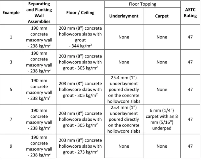
2.2 ASTC Examples - 203 mm Precast Concrete Hollowcore Floors
The following examples use the detailed calculation methods to determine the ASTC rating of
constructions of 190 mm thick hollow concrete block masonry units with a mass per unit area of 238
kg/m
2connected to floors and ceilings of 203 mm (8 inch) thick concrete hollowcore slabs. The
transmission loss values for the concrete block masonry wall are laboratory measured values from the
NRC Report RR-334 [6]. The transmission loss values for the precast concrete hollowcore slabs are
laboratory measured values from the NRC Client Reports A1-004972.1 and A1-012467.2. The
transmission loss values are summarized in Appendix A.
Also presented are examples with toppings of a 25.4 mm (1") thick underlayment poured directly on the
203 mm thick concrete hollowcore floor with a mass per unit area of 305 kg/m
2and a topping of the
underlayment with 6 mm (1/4") carpet and an 8mm (5/16") underpad. The improvements due to linings
are presented in Appendix B.
The examples and ASTC ratings are summarized in Table 1 for side-by-side rooms and in Table 2 for
one-above-the-other rooms.
Table 1: Summary of the examples with rooms side-by-side. All of the constructions have
separating and flanking walls of concrete masonry and concrete hollowcore floors
and ceilings.
Example
Separating
and Flanking
Wall
Assemblies
Floor / Ceiling
Floor Topping
ASTC
Rating
Underlayment
Carpet
1
190 mm
concrete
masonry wall
- 238 kg/m
2203 mm (8") concrete
hollowcore slabs with
grout
- 344 kg/m
2None
None
47
3
190 mm
concrete
masonry wall
- 238 kg/m
2203 mm (8") concrete
hollowcore slabs with
grout - 305 kg/m
2None
None
47
5
190 mm
concrete
masonry wall
- 238 kg/m
2203 mm (8") concrete
hollowcore slabs with
grout - 305 kg/m
225.4 mm (1")
underlayment
poured directly
on the concrete
hollowcore slabs
None
47
7
190 mm
concrete
masonry wall
- 238 kg/m
2203 mm (8") concrete
hollowcore slabs with
grout - 305 kg/m
225.4 mm (1")
underlayment
poured directly
on the concrete
hollowcore slabs
6 mm (1/4")
carpet with an 8
mm (5/16")
underpad
47
9
190 mm
concrete
masonry wall
- 238 kg/m
2203 mm (8") concrete
hollowcore slabs with
grout - 273 kg/m
2Table 2: Summary of the examples with rooms one-above-the-other. All of the constructions
have flanking walls of concrete masonry and concrete hollowcore floors and ceilings.
Example
Separating
Floor / Ceiling
Flanking Wall
Assemblies
Floor Topping
ASTC
Rating
Underlayment
Carpet
2
203 mm (8")
concrete
hollowcore
slabs with grout
- 344 kg/m
2190 mm concrete
masonry wall
- 238 kg/m
2None
None
54
4
203 mm (8")
concrete
hollowcore
slabs with grout
- 305 kg/m
2190 mm concrete
masonry wall
- 238 kg/m
2None
None
51
6
203 mm (8")
concrete
hollowcore
slabs with grout
- 305 kg/m
2190 mm concrete
masonry wall
- 238 kg/m
225.4 mm (1")
underlayment
poured directly on
the concrete
hollowcore slabs
None
52
8
203 mm (8")
concrete
hollowcore
slabs with grout
- 305 kg/m
2190 mm concrete
masonry wall
- 238 kg/m
225.4 mm (1")
underlayment
poured directly on
the concrete
hollowcore slabs
6 mm (1/4")
carpet with an 8
mm (5/16")
underpad
52
10
203 mm (8")
concrete
hollowcore
slabs with grout
- 273 kg/m
2190 mm concrete
masonry wall
- 238 kg/m
2None
None
49
Note that the examples in this report use transmission loss data which can be found in the following reports:
•
A1-012467.1 - The Transmission Loss of 203 mm Thick Prestressed Precast Concrete Hollowcore Floors
•
A1-004972.1 - Measurements of Airborne Sound Transmission Loss (ASTM E90) and Impact Sound
Transmission (ASTM E492) on One Bare Hollow Core Floor Assembly (203 mm)
•
A1-004972.2 - Measurements of Airborne Sound Transmission Loss (ASTM E90) and Impact Sound
Transmission (ASTM E492) on One Bare Hollow Core Floor Assembly (305 mm)
Horizontal Room Pair - 203 mm Precast Concrete Hollowcore Floor 344 kg/m
2Example 1: (Detailed Method)
•
Rooms side-by-side
•
Floors of concrete hollowcore precast slabs
2with walls of
normal weight concrete block walls with rigid junctions
Illustration for this case
Junction of a 190 mm concrete block
separating wall with a floor and ceiling of
203 mm thick precast concrete hollowcore
slabs. (Side view of Junctions 1 and 3)
Junction of the separating wall with a side
wall, both of 190 mm concrete block.
(Plan view of Junctions 2 and 4).
Separating wall assembly (loadbearing) with:
• One wythe of 190 mm hollow concrete block masonry
1constructed
using normal weight units not less than 53% solid, and with mass
per area of 238 kg/m2. No lining on the wall.
Junction 1: Bottom Junction (separating wall / floor) with:
• Floor assembly of precast concrete hollowcore slabs
2of
cross-section 203 mm thick and 2440 mm wide, fully grouted at joints
between adjacent slabs and with a mass per area of 344 kg/m
2.
• No topping, flooring or ceiling.
• Rigid mortared cross-junction with concrete block wall assembly.
Junction 2 or 4: Each Side (separating wall /abutting side wall) with:
• Abutting side wall and separating wall of hollow concrete block
masonry
1with a mass per area of 238 kg/m
2. No lining.
• Rigid mortared T-junctions
Junction 3: Top Junction (separating wall / ceiling) with:
• Ceiling assembly of precast concrete hollowcore slabs
2of
cross-section 203 mm thick and 2440 mm wide, fully grouted at joints
between adjacent slabs, with mass per area of 344 kg/m
2.
• No added ceiling lining
• Rigid mortared cross-junction with concrete block wall assembly
Acoustical Parameters
(For the notes in this table please see the corresponding endnotes on page 26.)
For the separating wall:
internal loss, η_i = 0.015 c_L = 3500
mass (kg/m2) = 238 f_c = 98 (Eq. C.2)
Reference
X-Junction 1 or 3 ISO 15712-1, Eq. E.3 6.1 11.6 8.8 8.8 0.506 T-Junction 2 or 4 ISO 15712-1, Eq. E.4 5.7 - 5.7 5.7 0.420 Total loss ISO 15712-1, Eq. C.1 0.039 at 500 Hz
For flanking elements F and f and Junctions 1 & 3 internal loss, η_i = 0.006 c_L = 3500
mass (kg/m2) = 344 f_c = 91 (Eq. C.2)
Total loss ISO 15712-1, Eq. C.1 0.030 at 500 Hz For flanking elements F and f and Junctions 2 & 4
internal loss, η_i = 0.015 c_L = 3500
mass (kg/m2) = 238 f_c = 98 (Eq. C.2) Total loss ISO 15712-1, Eq. C.1 0.045 at 500 Hz Total loss ISO 15712-1, Eq. C.1 0.042 at 500 Hz
��� ���′ ��� ��� Σ����
����
����
����,2
����,4
ISO Symbol Reference 125 Hz 250 Hz 500 Hz 1000 Hz 2000 Hz 4000 Hz ASTC
Separating Partition (190 mm concrete block wall)
Sound Transmission Loss RR-334, NRC-Mean BLK190(NW) 35 38 44 50 58 62 49
Structural Reverberation Time lab ISO 15712-1, Eq. C.5 0.299 0.191 0.119 0.072 0.042 0.024
Change by Lining on D No Lining 0 0 0 0 0 0
Change by Lining on d No Lining 0 0 0 0 0 0
Structural Reverberation Time in-situ ISO 15712-1, Eq. C.1-C.3 0.267 0.176 0.113 0.069 0.041 0.024
Leakage or Airborne Flanking Sealed & Blocked 0 0 0 0 0 0
Direct TL in-situ ISO 15712-1, Eq. 24 36 38 44 50 58 62 49
��,��� �� �� ��,���� ��,��� ��,����
ISO Symbol Reference 125 Hz 250 Hz 500 Hz 1000 Hz 2000 Hz 4000 Hz ASTC
Junction 1 (Rigid cross junction, 190 mm block separating wall / 203 mm precast hollow core floor 344 kg/m²)
Sound Transmission Loss F1 or f1 Measured 38 46 52 60 65 72 56
Structural Reverberation Time lab Measured 0.458 0.328 0.200 0.168 0.109 0.061
Change by Lining on F1 No Lining 0 0 0 0 0 0
Change by Lining on f1 No Lining 0 0 0 0 0 0
Structural Reverberation Time in-situ ISO 15712-1, Eq. C.1-C.3 0.320 0.220 0.147 0.096 0.061 0.039
TL in-situ for Element F1 ISO 15712-1 Eq. 19 39 47 54 62 67 74 58
TL in-situ for Element f1 ISO 15712-1 Eq. 19 39 47 54 62 67 74 58
Junction 1 - Coupling
In-situ Velocity Level Difference for Ff ISO 15712-1 Eq. 21, 22 9.6 9.8 10.0 10.4 10.8 11.2 In-situ Velocity Level Difference for Fd ISO 15712-1 Eq. 21, 22 11.8 12.0 12.3 12.8 13.4 14.0 In-situ Velocity Level Difference for Df ISO 15712-1 Eq. 21, 22 11.8 12.0 12.3 12.8 13.4 14.0
Flanking Transmssion Loss - Path Values
Flanking TL for Path Ff1 ISO 15712-1 Eq. 25a 47 55 62 70 76 83 66
Flanking TL for Path Fd1 ISO 15712-1 Eq. 25a 48 54 60 68 75 81 65
Flanking TL for Path Df1 ISO 15712-1 Eq. 25a 48 54 60 68 75 81 65
Flanking STC for Junction 1 43 50 56 64 71 77 60
Junction 2 (Rigid T-Junction, 190 mm block separating wall / 190 mm block facade wall)
Transmission Loss Element F2 RR-334, NRC-Mean BLK190(NW) 35 38 44 50 58 62 49
Structural Reverberation Time lab ISO 15712-1 Eq. C5 0.299 0.191 0.119 0.072 0.042 0.024
Change by Lining on F2 No Lining 0 0 0 0 0 0
Change by Lining on f2 No Lining 0 0 0 0 0 0
Structural Reverberation Time in-situ ISO 15712-1, Eq. C.1-C.3 0.226 0.149 0.098 0.061 0.037 0.022
TL in-situ for Element F2 ISO 15712-1 Eq. 19 36 39 45 51 59 62 50
TL in-situ for Element f2 ISO 15712-1 Eq. 19 36 39 45 51 59 62 50
Junction 2 - Coupling
In-situ Velocity Level Difference for Ff ISO 15712-1 Eq. 21, 22 10.8 11.0 11.4 11.9 12.6 13.3 In-situ Velocity Level Difference for Fd ISO 15712-1 Eq. 21, 22 10.9 11.2 11.5 12.1 12.9 13.6 In-situ Velocity Level Difference for Df ISO 15712-1 Eq. 21, 22 10.9 11.2 11.5 12.1 12.9 13.6
Flanking Transmssion Loss - Path Values
Flanking TL for Path Ff2 ISO 15712-1 Eq. 25a 48 51 57 64 73 76 62
Flanking TL for Path Fd2 ISO 15712-1 Eq. 25a 47 50 57 63 72 76 61
Flanking TL for Path Df2 ISO 15712-1 Eq. 25a 47 50 57 63 72 76 61
Flanking STC for Junction 2 43 46 52 59 68 71 57
Junction 3 (Rigid cross junction, 190 mm block separating wall / 203 mm precast hollow core ceiling slab 344 kg/m²)
All values are the same as for Junction 1
Flanking TL for Path Ff3 ISO 15712-1 Eq 25b 47 55 62 70 76 83 66
Flanking TL for Path Fd3 ISO 15712-1 Eq 25b 48 54 60 68 75 81 65
Flanking TL for Path Df3 ISO 15712-1 Eq 25b 48 54 60 68 75 81 65
Flanking STC for Junction 3 43 50 56 64 71 77 60
Junction 4 (Rigid T-junction, 190 mm block separating wall / 190 mm block corridor wall)
All of the input data is the same as for Junction 2, but different junctions at the ceiling and floor result in different loss factors than Junction 2. Structural Reverberation Time in-situ ISO 15712-1, Eq. C.1-C.3 0.244 0.163 0.105 0.065 0.039 0.023
TL in-situ for Element F4 ISO 15712-1 Eq. 19 36 39 45 50 58 62 50
TL in-situ for Element f4 ISO 15712-1 Eq. 19 36 39 45 50 58 62 50
Junction 4 - Coupling
In-situ Velocity Level Difference for Ff ISO 15712-1 Eq. 21, 22 10.4 10.7 11.1 11.7 12.3 13.2 In-situ Velocity Level Difference for Fd ISO 15712-1 Eq. 21, 22 10.7 11.0 11.4 12.0 12.7 13.6 In-situ Velocity Level Difference for Df ISO 15712-1 Eq. 21, 22 10.7 11.0 11.4 12.0 12.7 13.6
Flanking Transmssion Loss - Path Values
Flanking TL for Path Ff4 ISO 15712-1 Eq 25b 47 51 57 63 71 76 62
Flanking TL for Path Fd4 ISO 15712-1 Eq 25b 47 50 56 63 71 76 61
Flanking TL for Path Df4 ISO 15712-1 Eq 25b 47 50 56 63 71 76 61
��2,��� ��2�2 ��2� ���2 ��2,���� ��2,���� ��2 ��2 ��3�3 ��3� ���3 ��4�4 ��4� ���4 ��1,��� ��1�1 ��1� ��,�1,�1,���� ���1 ��1,���� ��1,���� ��,��� ��,���� ��,�1,�,���� ��,�,�1,���� ��,��� ��1 ��1 ��,���� ��,�2,�2,���� ��,�2,�,���� ��,�,�2,���� ��4,���� ��4,���� ��,���� ��,�4,�4,���� ��,�4,�,���� ��,�,�4,���� Example 1
Vertical Room Pair - 203 mm Precast Concrete Hollowcore Floor 344 kg/m
2Example 2: (Detailed Method)
•
Rooms one-above-the-other
•
Floors of concrete hollowcore precast slabs
2with walls of
normal weight concrete block walls with rigid junctions
Illustration for this case
Cross-junction of a separating floor
assembly of 203 mm thick precast
concrete hollowcore slabs with 190 mm
concrete block flanking walls.
(Side view of Junctions 1 and 3)
T-Junction of a separating floor of 203 mm
thick precast concrete hollowcore slabs
with 190 mm concrete block walls. (Plan
view of Junctions 2 and 4).
Separating wall assembly (loadbearing) with:
• Floor assembly of precast concrete hollowcore slabs
2of
cross-section 203 mm thick and 2440 mm wide, fully grouted at joints
between adjacent slabs and with a mass per area of 344 kg/m
2.
• No topping, flooring or ceiling.
Junction 1, 3, 4: Cross-junction of separating floor / flanking wall with:
• One wythe of 190 mm hollow concrete block masonry
1constructed
using normal weight units not less than 53% solid, and with mass
per area of 238 kg/m
2.
• No lining on the walls.
• Rigid mortared cross-junction with concrete block wall assembly.
Junction 2: T-Junction of separating floor / flanking wall with:
• Abutting side wall and separating wall of hollow concrete block
masonry
1with a mass per area of 238 kg/m
2.
• No lining on the walls.
• Rigid mortared T-junctions
NOTE: The sound transmission would be essentially unchanged if the
concrete hollowcore floor slabs were oriented perpendicular to the case
illustrated.
Acoustical Parameters
For the separating floor
internal loss, η_i = 0.006 c_L = 3500
mass (kg/m2) = 344 f_c = 91 (Eq. C.2)
Reference
X-Junction 1, 3 ISO 15712-1, Eq. E.3 11.6 6.1 8.8 8.8 0.782 X-Junction 4 ISO 15712-1, Eq. E.3 11.6 6.1 8.8 8.8 0.626 T-Junction 2 ISO 15712-1, Eq. E.4 8.1 - 5.8 5.8 0.657 Total loss ISO 15712-1, Eq. C.1 0.030 at 500 Hz
For flanking elements F and f and Junctions 1 & 3
internal loss, η_i = 0.015 c_L = 3500
mass (kg/m2) = 238 f_c = 98 (Eq. C.2)
Total loss ISO 15712-1, Eq. C.1 0.039 at 500 Hz For flanking elements F and f and Junctions 2 & 4
internal loss, η_i = 0.015 c_L = 3500
mass (kg/m2) = 238 f_c = 98 (Eq. C.2) Total loss ISO 15712-1, Eq. C.1 0.045 at 500 Hz Total loss ISO 15712-1, Eq. C.1 0.042 at 500 Hz
��� ���′ ��� ��� Σ����
����
����
����,2
����,4
ISO Symbol Reference 125 Hz 250 Hz 500 Hz 1000 Hz 2000 Hz 4000 Hz ASTC
Separating Partition (203 mm precast hollow core floor 344 kg/m²)
Sound Transmission Loss F1 or f1 Measured 38 46 52 60 65 72 56
Structural Reverberation Time lab Measured 0.458 0.328 0.200 0.168 0.109 0.061
Change by Lining on Source Side No Lining 0 0 0 0 0 0
Change by Lining on Receive Side No Lining 0 0 0 0 0 0
Structural Reverberation Time in-situ ISO 15712-1, Eq. C.1-C.3 0.320 0.220 0.147 0.096 0.061 0.039
Leakage or Airborne Flanking No leakage 0 0 0 0 0 0
Direct TL in-situ ISO 15712-1, Eq. 24 40 47 54 62 68 74 58
��,��� �� �� ��,���� ��,��� ��,����
ISO Symbol Reference 125 Hz 250 Hz 500 Hz 1000 Hz 2000 Hz 4000 Hz ASTC
Junction 1 (Rigid Cross junction, 203 mm precast hollow core floor 344 kg/m² / 190 mm block wall) Flanking Path Ff_1
Sound Transmission Loss F1 or f1 RR-334, NRC-Mean BLK190(NW) 35 38 44 50 58 62 49
Structural Reverberation Time lab ISO 15712-1, Eq. C.5 0.299 0.191 0.119 0.072 0.042 0.024
Change by Lining on Source Side No Lining 0 0 0 0 0 0
Change by Lining on Receive Side No Lining 0 0 0 0 0 0
Structural Reverberation Time in-situ ISO 15712-1, Eq. C.1-C.3 0.267 0.176 0.113 0.069 0.041 0.024
TL in-situ for Element F1 ISO 15712-1 Eq. 19 35 38 44 50 58 62 49
TL in-situ for Element f1 ISO 15712-1 Eq. 19 35 38 44 50 58 62 49
Junction 1 - Coupling
In-situ Velocity Level Difference for Ff ISO 15712-1 Eq. 21, 22 13.9 14.2 14.6 15.2 16.0 16.8 In-situ Velocity Level Difference for Fd ISO 15712-1 Eq. 21, 22 11.8 12.0 12.3 12.8 13.4 14.0 In-situ Velocity Level Difference for Df ISO 15712-1 Eq. 21, 22 11.8 12.0 12.3 12.8 13.4 14.0
Flanking Transmssion Loss - Path Values
Flanking TL for Path Ff1 ISO 15712-1 Eq. 25a 51 54 61 67 76 81 65
Flanking TL for Path Fd1 ISO 15712-1 Eq. 25a 50 56 62 70 77 83 67
Flanking TL for Path Df1 ISO 15712-1 Eq. 25a 50 56 62 70 77 83 67
Flanking STC for Junction 1 46 50 57 64 72 77 62
Junction 2 (Rigid T-junction, 203 mm precast hollow core floor 344 kg/m² / 190 mm block façade wall) Flanking Path Ff_2
Transmission Loss Element F2 RR-334, NRC-Mean BLK190(NW) 35 38 44 50 58 62 49
Structural Reverberation Time lab ISO 15712-1, Eq. C.5 0.299 0.191 0.119 0.072 0.042 0.024
Change by Lining on Source Side No Lining 0 0 0 0 0 0
Change by Lining on Receive Side No Lining 0 0 0 0 0 0
Structural Reverberation Time in-situ ISO 15712-1, Eq. C.1-C.3 0.226 0.149 0.098 0.061 0.037 0.022
TL in-situ for Element F2 ISO 15712-1 Eq. 19 36 39 45 51 59 62 50
TL in-situ for Element f2 ISO 15712-1 Eq. 19 36 39 45 51 59 62 50
Junction 2 - Coupling
In-situ Velocity Level Difference for Ff ISO 15712-1 Eq. 21, 22 11.1 11.4 11.7 12.3 13.0 13.7 In-situ Velocity Level Difference for Fd ISO 15712-1 Eq. 21, 22 9.6 9.8 10.1 10.5 11.1 11.7 In-situ Velocity Level Difference for Df ISO 15712-1 Eq. 21, 22 9.6 9.8 10.1 10.5 11.1 11.7
Flanking Transmssion Loss - Path Values
Flanking TL for Path Ff2 ISO 15712-1 Eq. 25a 50 53 60 66 75 79 65
Flanking TL for Path Fd2 ISO 15712-1 Eq. 25a 49 55 61 69 76 81 66
Flanking TL for Path Df2 ISO 15712-1 Eq. 25a 49 55 61 69 76 81 66
Flanking STC for Junction 2 44 49 56 63 71 75 60
Junction 3 (Rigid Cross junction, 203 mm precast hollow core floor 344 kg/m² / 190 mm block wall)
All values are the same as for Junction 1
Flanking STC for Junction 3 46 50 57 64 72 77 62
Junction 4 (Rigid Cross junction, 203 mm precast hollow core floor 344 kg/m² / 190 mm block corridor wall)
All of the input data is the same as for Junction 2, but different junctions at the ceiling and floor result in different loss factors than Junction 2. Structural Reverberation Time in-situ ISO 15712-1, Eq. C.1-C.3 0.244 0.163 0.105 0.065 0.039 0.023
TL in-situ for Element F4 ISO 15712-1 Eq. 19 36 39 45 50 58 62 50
TL in-situ for Element f4 ISO 15712-1 Eq. 19 36 39 45 50 58 62 50
Junction 4 - Coupling
In-situ Velocity Level Difference for Ff ISO 15712-1 Eq. 21, 22 14.2 14.5 14.9 15.5 16.2 17.0 In-situ Velocity Level Difference for Fd ISO 15712-1 Eq. 21, 22 12.4 12.6 13.0 13.4 14.0 14.6 In-situ Velocity Level Difference for Df ISO 15712-1 Eq. 21, 22 12.4 12.6 13.0 13.4 14.0 14.6
Flanking Transmssion Loss - Path Values
Flanking TL for Path Ff4 ISO 15712-1 Eq 25b 53 57 63 69 77 82 68
Flanking TL for Path Fd4 ISO 15712-1 Eq 25b 52 57 64 71 78 84 68
Flanking TL for Path Df4 ISO 15712-1 Eq 25b 52 57 64 71 78 84 68
Flanking STC for Junction 4 47 52 59 65 73 78 63
��1,��� ��1�1 ��1� ��,�1,�1,���� ���1 ��1,���� ��1,���� ��,��� ��,���� ��,�1,�,���� ��,�,�1,���� ��1 ��1 ��2,��� ��2�2 ��2� ���2 ��2,���� ��2,���� ��2 ��2 ��4�4 ��4� ���4 ��,��� ��,���� ��,�2,�2,���� ��,�2,�,���� ��,�,�2,���� ��4,���� ��4,���� ��,���� ��,�4,�4,���� ��,�4,�,���� ��,�,�4,���� Example 2
Horizontal Room Pair - 203 mm Precast Concrete Hollowcore Floor 305 kg/m
2Example 3: (Detailed Method)
•
Rooms side-by-side
•
Floors of precast concrete hollowcore slabs
2with walls of
normal weight concrete block walls with rigid junctions
Illustration for this case
Junction of a 190 mm concrete block
separating wall with a floor and ceiling of
203 mm thick precast concrete hollowcore
slabs. (Side view of Junctions 1 and 3)
Junction of the separating wall with a side
wall, both of 190 mm concrete block.
(Plan view of Junctions 2 and 4).
Separating wall assembly (loadbearing) with:
• One wythe of 190 mm hollow concrete block masonry1 constructed
using normal weight units not less than 53% solid, and with mass
per area of 238 kg/m2. No lining on the wall.
Junction 1: Bottom Junction (separating wall / floor) with:
• Floor assembly of precast concrete hollowcore slabs
2of
cross-section 203 mm thick and 2440 mm wide, fully grouted at joints
between adjacent slabs and with a mass per area of 305 kg/m
2.
• No topping, flooring or ceiling.
• Rigid mortared cross-junction with concrete block wall assembly.
Junction 2 or 4: Each Side (separating wall /abutting side wall) with:
• Abutting side wall and separating wall of hollow concrete block
masonry
1with a mass per area of 238 kg/m
2. No lining.
• Rigid mortared T-junctions
Junction 3: Top Junction (separating wall / ceiling) with:
• Ceiling assembly of precast concrete hollowcore slabs
2of
cross-section 203 mm thick and 2440 mm wide, fully grouted at joints
between adjacent slabs, with mass per area of 305 kg/m
2.
• No added ceiling lining
• Rigid mortared cross-junction with concrete block wall assembly
Acoustical Parameters
(For the notes in this table please see the corresponding endnotes on page 26.)
For the separating wall:
internal loss, η_i = 0.015 c_L = 3500
mass (kg/m2) = 238 f_c = 98 (Eq. C.2)
Reference
X-Junction 1 or 3 ISO 15712-1, Eq. E.3 6.9 10.6 8.8 8.8 0.663 T-Junction 2 or 4 ISO 15712-1, Eq. E.4 5.7 - 5.7 5.7 0.420 Total loss ISO 15712-1, Eq. C.1 0.043 at 500 Hz
For flanking elements F and f and Junctions 1 & 3 internal loss, η_i = 0.006 c_L = 3500
mass (kg/m2) = 305 f_c = 160 (Eq. C.2)
Total loss ISO 15712-1, Eq. C.1 0.025 at 500 Hz For flanking elements F and f and Junctions 2 & 4
internal loss, η_i = 0.015 c_L = 3500
mass (kg/m2) = 238 f_c = 98 (Eq. C.2) Total loss ISO 15712-1, Eq. C.1 0.050 at 500 Hz Total loss ISO 15712-1, Eq. C.1 0.046 at 500 Hz
��� ���′ ��� ��� Σ����
����
����
����,2
����,4
ISO Symbol Reference 125 Hz 250 Hz 500 Hz 1000 Hz 2000 Hz 4000 Hz ASTC
Separating Partition (190 mm concrete block wall)
Sound Transmission Loss RR-334, NRC-Mean BLK190(NW) 35 38 44 50 58 62 49
Structural Reverberation Time lab ISO 15712-1, Eq. C.5 0.299 0.191 0.119 0.072 0.042 0.024
Change by Lining on D No Lining 0 0 0 0 0 0
Change by Lining on d No Lining 0 0 0 0 0 0
Structural Reverberation Time in-situ ISO 15712-1, Eq. C.1-C.3 0.238 0.157 0.102 0.063 0.038 0.022
Leakage or Airborne Flanking Sealed & Blocked 0 0 0 0 0 0
Direct TL in-situ ISO 15712-1, Eq. 24 36 39 45 51 59 62 50
��,��� �� �� ��,���� ��,��� ��,����
ISO Symbol Reference 125 Hz 250 Hz 500 Hz 1000 Hz 2000 Hz 4000 Hz ASTC
Junction 1 (Rigid cross junction, 190 mm block separating wall / 203 mm precast hollow core floor 305 kg/m²)
Sound Transmission Loss F1 or f1 Measured A1-012467.2 36 43 51 57 63 71 54
Structural Reverberation Time lab Measured 0.283 0.192 0.129 0.085 0.055 0.034
Change by Lining on F1 No Lining 0 0 0 0 0 0
Change by Lining on f1 No Lining 0 0 0 0 0 0
Structural Reverberation Time in-situ ISO 15712-1, Eq. C.1-C.3 0.383 0.267 0.176 0.116 0.073 0.046
TL in-situ for Element F1 ISO 15712-1 Eq. 19 35 41 50 55 62 70 53
TL in-situ for Element f1 ISO 15712-1 Eq. 19 35 41 50 55 62 70 53
Junction 1 - Coupling
In-situ Velocity Level Difference for Ff ISO 15712-1 Eq. 21, 22 9.7 9.7 10.0 10.4 10.8 11.4 In-situ Velocity Level Difference for Fd ISO 15712-1 Eq. 21, 22 11.5 11.7 12.0 12.5 13.1 13.8 In-situ Velocity Level Difference for Df ISO 15712-1 Eq. 21, 22 11.5 11.7 12.0 12.5 13.1 13.8
Flanking Transmssion Loss - Path Values
Flanking TL for Path Ff1 ISO 15712-1 Eq. 25a 43 49 58 63 71 79 61
Flanking TL for Path Fd1 ISO 15712-1 Eq. 25a 46 51 58 64 72 79 62
Flanking TL for Path Df1 ISO 15712-1 Eq. 25a 46 51 58 64 72 79 62
Flanking STC for Junction 1 40 46 53 59 67 74 57
Junction 2 (Rigid T-Junction, 190 mm block separating wall / 190 mm block facade wall)
Transmission Loss Element F2 RR-334, NRC-Mean BLK190(NW) 35 38 44 50 58 62 49
Structural Reverberation Time lab ISO 15712-1 Eq. C5 0.299 0.191 0.119 0.072 0.042 0.024
Change by Lining on F2 No Lining 0 0 0 0 0 0
Change by Lining on f2 No Lining 0 0 0 0 0 0
Structural Reverberation Time in-situ ISO 15712-1, Eq. C.1-C.3 0.202 0.135 0.088 0.056 0.034 0.020
TL in-situ for Element F2 ISO 15712-1 Eq. 19 37 39 45 51 59 63 50
TL in-situ for Element f2 ISO 15712-1 Eq. 19 37 39 45 51 59 63 50
Junction 2 - Coupling
In-situ Velocity Level Difference for Ff ISO 15712-1 Eq. 21, 22 11.2 11.5 11.8 12.3 12.9 13.7 In-situ Velocity Level Difference for Fd ISO 15712-1 Eq. 21, 22 11.4 11.6 12.0 12.5 13.2 14.0 In-situ Velocity Level Difference for Df ISO 15712-1 Eq. 21, 22 11.4 11.6 12.0 12.5 13.2 14.0
Flanking Transmssion Loss - Path Values
Flanking TL for Path Ff2 ISO 15712-1 Eq. 25a 49 51 58 64 73 78 63
Flanking TL for Path Fd2 ISO 15712-1 Eq. 25a 48 51 57 64 72 77 62
Flanking TL for Path Df2 ISO 15712-1 Eq. 25a 48 51 57 64 72 77 62
Flanking STC for Junction 2 44 46 53 59 68 73 58
Junction 3 (Rigid cross junction, 190 mm block separating wall / 203 mm precast hollow core ceiling slab 305 kg/m²)
All values are the same as for Junction 1
Flanking TL for Path Ff3 ISO 15712-1 Eq 25b 43 49 58 63 71 79 61
Flanking TL for Path Fd3 ISO 15712-1 Eq 25b 46 51 58 64 72 79 62
Flanking TL for Path Df3 ISO 15712-1 Eq 25b 46 51 58 64 72 79 62
Flanking STC for Junction 3 44 45 53 59 67 74 57
Junction 4 (Rigid T-junction, 190 mm block separating wall / 190 mm block corridor wall)
All of the input data is the same as for Junction 2, but different junctions at the ceiling and floor result in different loss factors than Junction 2. Structural Reverberation Time in-situ ISO 15712-1, Eq. C.1-C.3 0.223 0.147 0.096 0.059 0.037 0.021
TL in-situ for Element F4 ISO 15712-1 Eq. 19 36 39 45 51 59 63 50
TL in-situ for Element f4 ISO 15712-1 Eq. 19 36 39 45 51 59 63 50
Junction 4 - Coupling
In-situ Velocity Level Difference for Ff ISO 15712-1 Eq. 21, 22 10.8 11.1 11.5 12.0 12.6 13.5 In-situ Velocity Level Difference for Fd ISO 15712-1 Eq. 21, 22 11.2 11.5 11.8 12.4 13.0 13.9 In-situ Velocity Level Difference for Df ISO 15712-1 Eq. 21, 22 11.2 11.5 11.8 12.4 13.0 13.9
Flanking Transmssion Loss - Path Values
Flanking TL for Path Ff4 ISO 15712-1 Eq 25b 48 51 57 64 73 77 62
Flanking TL for Path Fd4 ISO 15712-1 Eq 25b 48 51 57 64 72 77 62
Flanking TL for Path Df4 ISO 15712-1 Eq 25b 48 51 57 64 72 77 62
��2,��� ��2�2 ��2� ���2 ��2,���� ��2,���� ��2 ��2 ��3�3 ��3� ���3 ��4�4 ��4� ���4 ��1,��� ��1�1 ��1� ��,�1,�1,���� ���1 ��1,���� ��1,���� ��,��� ��,���� ��,�1,�,���� ��,�,�1,���� ��,��� ��1 ��1 ��,���� ��,�2,�2,���� ��,�2,�,���� ��,�,�2,���� ��4,���� ��4,���� ��,���� ��,�4,�4,���� ��,�4,�,���� ��,�,�4,���� Example 3
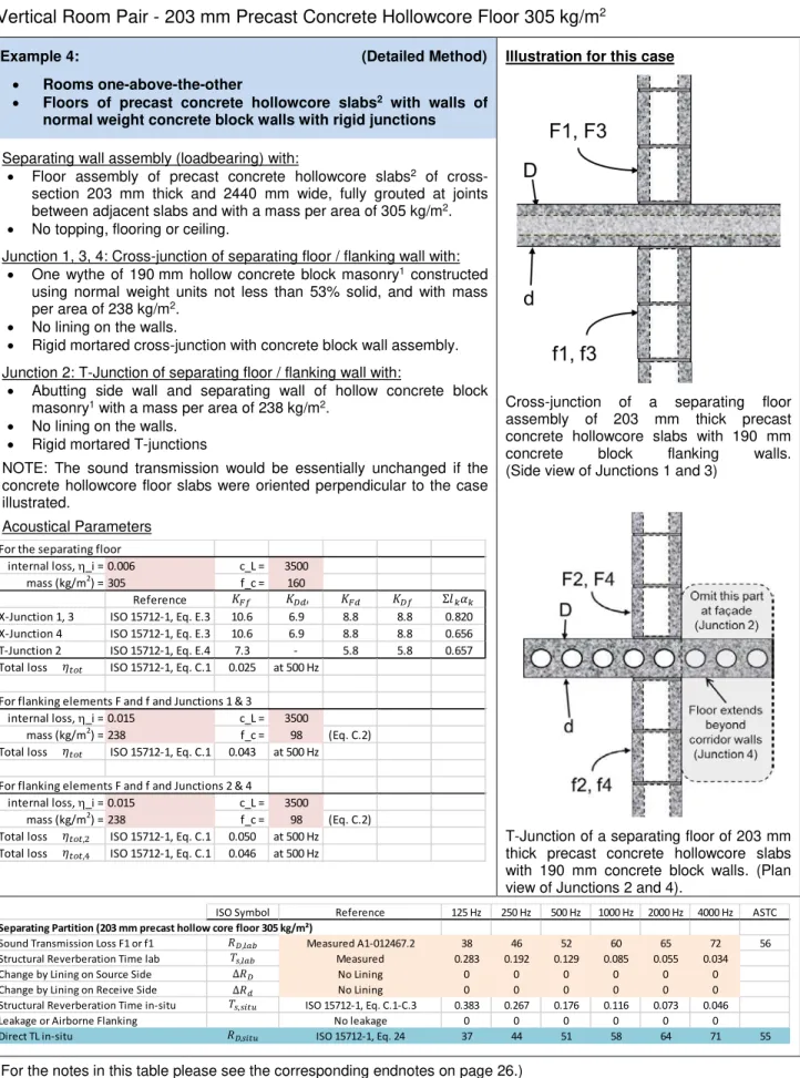
Vertical Room Pair - 203 mm Precast Concrete Hollowcore Floor 305 kg/m
2Example 4: (Detailed Method)
•
Rooms one-above-the-other
•
Floors of precast concrete hollowcore slabs
2with walls of
normal weight concrete block walls with rigid junctions
Illustration for this case
Cross-junction of a separating floor
assembly of 203 mm thick precast
concrete hollowcore slabs with 190 mm
concrete block flanking walls.
(Side view of Junctions 1 and 3)
T-Junction of a separating floor of 203 mm
thick precast concrete hollowcore slabs
with 190 mm concrete block walls. (Plan
view of Junctions 2 and 4).
Separating wall assembly (loadbearing) with:
• Floor assembly of precast concrete hollowcore slabs
2of
cross-section 203 mm thick and 2440 mm wide, fully grouted at joints
between adjacent slabs and with a mass per area of 305 kg/m
2.
• No topping, flooring or ceiling.
Junction 1, 3, 4: Cross-junction of separating floor / flanking wall with:
• One wythe of 190 mm hollow concrete block masonry
1constructed
using normal weight units not less than 53% solid, and with mass
per area of 238 kg/m
2.
• No lining on the walls.
• Rigid mortared cross-junction with concrete block wall assembly.
Junction 2: T-Junction of separating floor / flanking wall with:
• Abutting side wall and separating wall of hollow concrete block
masonry
1with a mass per area of 238 kg/m
2.
• No lining on the walls.
• Rigid mortared T-junctions
NOTE: The sound transmission would be essentially unchanged if the
concrete hollowcore floor slabs were oriented perpendicular to the case
illustrated.
Acoustical Parameters
For the separating floor
internal loss, η_i = 0.006 c_L = 3500 mass (kg/m2) = 305 f_c = 160
Reference
X-Junction 1, 3 ISO 15712-1, Eq. E.3 10.6 6.9 8.8 8.8 0.820 X-Junction 4 ISO 15712-1, Eq. E.3 10.6 6.9 8.8 8.8 0.656 T-Junction 2 ISO 15712-1, Eq. E.4 7.3 - 5.8 5.8 0.657 Total loss ISO 15712-1, Eq. C.1 0.025 at 500 Hz
For flanking elements F and f and Junctions 1 & 3
internal loss, η_i = 0.015 c_L = 3500
mass (kg/m2) = 238 f_c = 98 (Eq. C.2)
Total loss ISO 15712-1, Eq. C.1 0.043 at 500 Hz For flanking elements F and f and Junctions 2 & 4
internal loss, η_i = 0.015 c_L = 3500
mass (kg/m2) = 238 f_c = 98 (Eq. C.2) Total loss ISO 15712-1, Eq. C.1 0.050 at 500 Hz Total loss ISO 15712-1, Eq. C.1 0.046 at 500 Hz
��� ���′ ��� ��� Σ����
����
����
����,2
����,4
ISO Symbol Reference 125 Hz 250 Hz 500 Hz 1000 Hz 2000 Hz 4000 Hz ASTC
Separating Partition (203 mm precast hollow core floor 305 kg/m²)
Sound Transmission Loss F1 or f1 Measured A1-012467.2 38 46 52 60 65 72 56
Structural Reverberation Time lab Measured 0.283 0.192 0.129 0.085 0.055 0.034
Change by Lining on Source Side No Lining 0 0 0 0 0 0
Change by Lining on Receive Side No Lining 0 0 0 0 0 0
Structural Reverberation Time in-situ ISO 15712-1, Eq. C.1-C.3 0.383 0.267 0.176 0.116 0.073 0.046
Leakage or Airborne Flanking No leakage 0 0 0 0 0 0
Direct TL in-situ ISO 15712-1, Eq. 24 37 44 51 58 64 71 55
��,��� �� �� ��,���� ��,��� ��,����
ISO Symbol Reference 125 Hz 250 Hz 500 Hz 1000 Hz 2000 Hz 4000 Hz ASTC
Junction 1 (Rigid Cross junction, 203 mm precast hollow core floor 305 kg/m² / 190 mm block wall) Flanking Path Ff_1
Sound Transmission Loss F1 or f1 RR-334, NRC-Mean BLK190(NW) 35 38 44 50 58 62 49
Structural Reverberation Time lab ISO 15712-1, Eq. C.5 0.299 0.191 0.119 0.072 0.042 0.024
Change by Lining on Source Side No Lining 0 0 0 0 0 0
Change by Lining on Receive Side No Lining 0 0 0 0 0 0
Structural Reverberation Time in-situ ISO 15712-1, Eq. C.1-C.3 0.238 0.157 0.102 0.063 0.038 0.022
TL in-situ for Element F1 ISO 15712-1 Eq. 19 36 39 45 51 58 62 50
TL in-situ for Element f1 ISO 15712-1 Eq. 19 36 39 45 51 58 62 50
Junction 1 - Coupling
In-situ Velocity Level Difference for Ff ISO 15712-1 Eq. 21, 22 13.4 13.7 14.0 14.7 15.3 16.2 In-situ Velocity Level Difference for Fd ISO 15712-1 Eq. 21, 22 11.5 11.7 12.0 12.5 13.1 13.8 In-situ Velocity Level Difference for Df ISO 15712-1 Eq. 21, 22 11.5 11.7 12.0 12.5 13.1 13.8
Flanking Transmssion Loss - Path Values
Flanking TL for Path Ff1 ISO 15712-1 Eq. 25a 51 55 61 68 75 80 66
Flanking TL for Path Fd1 ISO 15712-1 Eq. 25a 49 54 61 68 75 81 65
Flanking TL for Path Df1 ISO 15712-1 Eq. 25a 49 54 61 68 75 81 65
Flanking STC for Junction 1 45 50 56 63 70 76 61
Junction 2 (Rigid T-junction, 203 mm precast hollow core floor 305 kg/m² / 190 mm block façade wall) Flanking Path Ff_2
Transmission Loss Element F2 RR-334, NRC-Mean BLK190(NW) 35 38 44 50 58 62 49
Structural Reverberation Time lab ISO 15712-1, Eq. C.5 0.299 0.191 0.119 0.072 0.042 0.024
Change by Lining on Source Side No Lining 0 0 0 0 0 0
Change by Lining on Receive Side No Lining 0 0 0 0 0 0
Structural Reverberation Time in-situ ISO 15712-1, Eq. C.1-C.3 0.202 0.135 0.088 0.056 0.034 0.020
TL in-situ for Element F2 ISO 15712-1 Eq. 19 37 39 45 51 59 63 50
TL in-situ for Element f2 ISO 15712-1 Eq. 19 37 39 45 51 59 63 50
Junction 2 - Coupling
In-situ Velocity Level Difference for Ff ISO 15712-1 Eq. 21, 22 10.8 11.0 11.4 11.8 12.4 13.2 In-situ Velocity Level Difference for Fd ISO 15712-1 Eq. 21, 22 9.4 9.5 9.9 10.2 10.8 11.4 In-situ Velocity Level Difference for Df ISO 15712-1 Eq. 21, 22 9.4 9.5 9.9 10.2 10.8 11.4
Flanking Transmssion Loss - Path Values
Flanking TL for Path Ff2 ISO 15712-1 Eq. 25a 51 53 59 66 75 79 64
Flanking TL for Path Fd2 ISO 15712-1 Eq. 25a 48 53 59 66 74 80 64
Flanking TL for Path Df2 ISO 15712-1 Eq. 25a 48 53 59 66 74 80 64
Flanking STC for Junction 2 44 48 55 61 69 75 59
Junction 3 (Rigid Cross junction, 203 mm precast hollow core floor 305 kg/m² / 190 mm block wall)
All values are the same as for Junction 1
Flanking STC for Junction 3 45 50 56 63 70 76 61
Junction 4 (Rigid Cross junction, 203 mm precast hollow core floor 305 kg/m² / 190 mm block corridor wall)
All of the input data is the same as for Junction 2, but different junctions at the ceiling and floor result in different loss factors than Junction 2. Structural Reverberation Time in-situ ISO 15712-1, Eq. C.1-C.3 0.223 0.147 0.096 0.059 0.037 0.021
TL in-situ for Element F4 ISO 15712-1 Eq. 19 36 39 45 51 59 63 50
TL in-situ for Element f4 ISO 15712-1 Eq. 19 36 39 45 51 59 63 50
Junction 4 - Coupling
In-situ Velocity Level Difference for Ff ISO 15712-1 Eq. 21, 22 13.7 14.0 14.3 14.9 15.5 16.4 In-situ Velocity Level Difference for Fd ISO 15712-1 Eq. 21, 22 12.2 12.4 12.7 13.1 13.7 14.4 In-situ Velocity Level Difference for Df ISO 15712-1 Eq. 21, 22 12.2 12.4 12.7 13.1 13.7 14.4
Flanking Transmssion Loss - Path Values
Flanking TL for Path Ff4 ISO 15712-1 Eq 25b 53 56 62 69 78 82 67
Flanking TL for Path Fd4 ISO 15712-1 Eq 25b 50 56 62 69 77 83 66
Flanking TL for Path Df4 ISO 15712-1 Eq 25b 50 56 62 69 77 83 66
Flanking STC for Junction 4 46 51 57 64 72 78 62
��1,��� ��1�1 ��1� ��,�1,�1,���� ���1 ��1,���� ��1,���� ��,��� ��,���� ��,�1,�,���� ��,�,�1,���� ��1 ��1 ��2,��� ��2�2 ��2� ���2 ��2,���� ��2,���� ��2 ��2 ��4�4 ��4� ���4 ��,��� ��,���� ��,�2,�2,���� ��,�2,�,���� ��,�,�2,���� ��4,���� ��4,���� ��,���� ��,�4,�4,���� ��,�4,�,���� ��,�,�4,���� Example 4
Horizontal Room Pair - 203 mm Concrete Hollowcore Floor 305 kg/m
2- Underlayment Topping
Example 5: (Detailed Method)
•
Rooms side-by-side
•
Floors of precast concrete hollowcore slabs
2with walls of
normal weight concrete block walls with rigid junctions
Illustration for this case
Junction of a 190 mm concrete block
separating wall with a floor and ceiling of
203 mm thick precast concrete hollowcore
slabs. (Side view of Junctions 1 and 3)
Junction of the separating wall with a side
wall, both of 190 mm concrete block.
(Plan view of Junctions 2 and 4).
Separating wall assembly (loadbearing) with:
• One wythe of 190 mm hollow concrete block masonry
1constructed
using normal weight units not less than 53% solid, and with mass
per area of 238 kg/m
2. No lining on the wall.
Junction 1: Bottom Junction (separating wall / floor) with:
• Floor assembly of concrete hollowcore precast slabs
2of
cross-section 203 mm thick and 2440 mm wide, fully grouted at joints
between adjacent slabs and with a mass per area of 305 kg/m
2.
• Topping of 25.4 mm (1") underlayment poured directly on the slabs.
• Rigid mortared cross-junction with concrete block wall assembly.
Junction 2 or 4: Each Side (separating wall /abutting side wall) with:
• Abutting side wall and separating wall of hollow concrete block
masonry
1with a mass per area of 238 kg/m
2. No lining.
• Rigid mortared T-junctions
Junction 3: Top Junction (separating wall / ceiling) with:
• Ceiling assembly of concrete hollowcore precast slabs2 of
cross-section 203 mm thick and 2440 mm wide, fully grouted at joints
between adjacent slabs, with mass per area of 305 kg/m2.
• No added ceiling lining
• Rigid mortared cross-junction with concrete block wall assembly
Acoustical Parameters
(For the notes in this table please see the corresponding endnotes on page 26.)
For the separating wall:
internal loss, η_i = 0.015 c_L = 3500
mass (kg/m2) = 238 f_c = 98 (Eq. C.2)
Reference
X-Junction 1 or 3 ISO 15712-1, Eq. E.3 6.9 10.6 8.8 8.8 0.602 T-Junction 2 or 4 ISO 15712-1, Eq. E.4 5.7 - 5.7 5.7 0.420 Total loss ISO 15712-1, Eq. C.1 0.042 at 500 Hz
For flanking elements F and f and Junctions 1 & 3 internal loss, η_i = 0.006 c_L = 3500
mass (kg/m2) = 305 f_c = 125 (Eq. C.2)
Total loss ISO 15712-1, Eq. C.1 0.026 at 500 Hz For flanking elements F and f and Junctions 2 & 4
internal loss, η_i = 0.015 c_L = 3500
mass (kg/m2) = 238 f_c = 98 (Eq. C.2) Total loss ISO 15712-1, Eq. C.1 0.048 at 500 Hz Total loss ISO 15712-1, Eq. C.1 0.044 at 500 Hz
��� ���′ ��� ��� Σ����
����
����
����,2
����,4
ISO Symbol Reference 125 Hz 250 Hz 500 Hz 1000 Hz 2000 Hz 4000 Hz ASTC
Separating Partition (190 mm concrete block wall)
Sound Transmission Loss RR-334, NRC-Mean BLK190(NW) 35 38 44 50 58 62 49
Structural Reverberation Time lab ISO 15712-1, Eq. C.5 0.299 0.191 0.119 0.072 0.042 0.024
Change by Lining on D No Lining 0 0 0 0 0 0
Change by Lining on d No Lining 0 0 0 0 0 0
Structural Reverberation Time in-situ ISO 15712-1, Eq. C.1-C.3 0.248 0.163 0.105 0.065 0.039 0.023
Leakage or Airborne Flanking Sealed & Blocked 0 0 0 0 0 0
Direct TL in-situ ISO 15712-1, Eq. 24 36 39 45 51 58 62 50
��,��� �� �� ��,���� ��,��� ��,����
ISO Symbol Reference 125 Hz 250 Hz 500 Hz 1000 Hz 2000 Hz 4000 Hz ASTC
Junction 1 (Rigid cross junction, 190 mm block separating wall / 203 mm precast hollow core floor 305 kg/m²)
Sound Transmission Loss F1 or f1 Measured A1-012467.2 36 43 51 57 63 71 54
Structural Reverberation Time lab Measured 0.283 0.192 0.129 0.085 0.055 0.034
Change by Lining on F1 25.4 mm Underlayment 2 0 1 4 4 3
Change by Lining on f1 25.4 mm Underlayment 2 0 1 4 4 3
Structural Reverberation Time in-situ ISO 15712-1, Eq. C.1-C.3 0.359 0.251 0.169 0.110 0.069 0.042
TL in-situ for Element F1 ISO 15712-1 Eq. 19 35 41 50 56 62 70 53
TL in-situ for Element f1 ISO 15712-1 Eq. 19 35 41 50 56 62 70 53
Junction 1 - Coupling
In-situ Velocity Level Difference for Ff ISO 15712-1 Eq. 21, 22 10.0 10.0 10.2 10.6 11.1 11.7 In-situ Velocity Level Difference for Fd ISO 15712-1 Eq. 21, 22 11.6 11.8 12.1 12.6 13.2 13.9 In-situ Velocity Level Difference for Df ISO 15712-1 Eq. 21, 22 11.6 11.8 12.1 12.6 13.2 13.9
Flanking Transmssion Loss - Path Values
Flanking TL for Path Ff1 ISO 15712-1 Eq. 25a 47 50 60 72 79 85 63
Flanking TL for Path Fd1 ISO 15712-1 Eq. 25a 48 51 59 68 76 82 63
Flanking TL for Path Df1 ISO 15712-1 Eq. 25a 48 51 59 68 76 82 63
Flanking STC for Junction 1 43 46 55 64 72 78 58
Junction 2 (Rigid T-Junction, 190 mm block separating wall / 190 mm block facade wall)
Transmission Loss Element F2 RR-334, NRC-Mean BLK190(NW) 35 38 44 50 58 62 49
Structural Reverberation Time lab ISO 15712-1 Eq. C5 0.299 0.191 0.119 0.072 0.042 0.024
Change by Lining on F2 No Lining 0 0 0 0 0 0
Change by Lining on f2 No Lining 0 0 0 0 0 0
Structural Reverberation Time in-situ ISO 15712-1, Eq. C.1-C.3 0.210 0.140 0.092 0.058 0.035 0.021
TL in-situ for Element F2 ISO 15712-1 Eq. 19 37 39 45 51 59 63 50
TL in-situ for Element f2 ISO 15712-1 Eq. 19 37 39 45 51 59 63 50
Junction 2 - Coupling
In-situ Velocity Level Difference for Ff ISO 15712-1 Eq. 21, 22 11.1 11.3 11.7 12.1 12.8 13.5 In-situ Velocity Level Difference for Fd ISO 15712-1 Eq. 21, 22 11.2 11.5 11.9 12.4 13.0 13.8 In-situ Velocity Level Difference for Df ISO 15712-1 Eq. 21, 22 11.2 11.5 11.9 12.4 13.0 13.8
Flanking Transmssion Loss - Path Values
Flanking TL for Path Ff2 ISO 15712-1 Eq. 25a 49 51 58 64 73 77 62
Flanking TL for Path Fd2 ISO 15712-1 Eq. 25a 48 51 57 64 72 77 62
Flanking TL for Path Df2 ISO 15712-1 Eq. 25a 48 51 57 64 72 77 62
Flanking STC for Junction 2 44 46 53 59 68 72 57
Junction 3 (Rigid cross junction, 190 mm block separating wall / 203 mm precast hollow core ceiling slab 305 kg/m²)
All values are the same as for Junction 1 except the topping
Flanking TL for Path Ff3 ISO 15712-1 Eq 25b 43 49 58 65 71 80 61
Flanking TL for Path Fd3 ISO 15712-1 Eq 25b 46 51 58 65 72 79 62
Flanking TL for Path Df3 ISO 15712-1 Eq 25b 46 51 58 65 72 79 62
Flanking STC for Junction 3 44 45 53 60 67 75 57
Junction 4 (Rigid T-junction, 190 mm block separating wall / 190 mm block corridor wall)
All of the input data is the same as for Junction 2, but different junctions at the ceiling and floor result in different loss factors than Junction 2. Structural Reverberation Time in-situ ISO 15712-1, Eq. C.1-C.3 0.232 0.154 0.100 0.061 0.038 0.022
TL in-situ for Element F4 ISO 15712-1 Eq. 19 36 39 45 51 58 62 50
TL in-situ for Element f4 ISO 15712-1 Eq. 19 36 39 45 51 58 62 50
Junction 4 - Coupling
In-situ Velocity Level Difference for Ff ISO 15712-1 Eq. 21, 22 10.6 10.9 11.3 11.9 12.5 13.3 In-situ Velocity Level Difference for Fd ISO 15712-1 Eq. 21, 22 11.0 11.3 11.7 12.3 12.9 13.7 In-situ Velocity Level Difference for Df ISO 15712-1 Eq. 21, 22 11.0 11.3 11.7 12.3 12.9 13.7
Flanking Transmssion Loss - Path Values
Flanking TL for Path Ff4 ISO 15712-1 Eq 25b 48 51 57 64 71 76 62
Flanking TL for Path Fd4 ISO 15712-1 Eq 25b 47 51 57 64 72 76 62
Flanking TL for Path Df4 ISO 15712-1 Eq 25b 47 51 57 64 72 76 62
��2,��� ��2�2 ��2� ���2 ��2,���� ��2,���� ��2 ��2 ��3�3 ��3� ���3 ��4�4 ��4� ���4 ��1,��� ��1�1 ��1� ��,�1,�1,���� ���1 ��1,���� ��1,���� ��,��� ��,���� ��,�1,�,���� ��,�,�1,���� ��,��� ��1 ��1 ��,���� ��,�2,�2,���� ��,�2,�,���� ��,�,�2,���� ��4,���� ��4,���� ��,���� ��,�4,�4,���� ��,�4,�,���� ��,�,�4,���� Example 5
Vertical Room Pair - 203 mm Precast Hollowcore Floor 305 kg/m
2- Underlayment Topping
Example 6: (Detailed Method)
•
Rooms one-above-the-other
•
Floors of precast concrete hollowcore slabs
2with walls of
normal weight concrete block walls with rigid junctions
Illustration for this case
Cross-junction of a separating floor
assembly of 203 mm thick precast
concrete hollowcore slabs with 190 mm
concrete block flanking walls.
(Side view of Junctions 1 and 3)
T-Junction of a separating floor of 203 mm
thick precast concrete hollowcore slabs
with 190 mm concrete block walls. (Plan
view of Junctions 2 and 4).
Separating wall assembly (loadbearing) with:
• Floor assembly of precast concrete hollowcore slabs
2of
cross-section 203 mm thick and 2440 mm wide, fully grouted at joints
between adjacent slabs and with a mass per area of 305 kg/m
2.
• Topping of 25.4 mm (1") underlayment poured directly on the slabs.
Junction 1, 3, 4: Cross-junction of separating floor / flanking wall with:
• One wythe of 190 mm hollow concrete block masonry
1constructed
using normal weight units not less than 53% solid, and with mass
per area of 238 kg/m2.
• No lining on the walls.
• Rigid mortared cross-junction with concrete block wall assembly.
Junction 2: T-Junction of separating floor / flanking wall with:
• Abutting side wall and separating wall of hollow concrete block
masonry
1with a mass per area of 238 kg/m
2.
• No lining on the walls.
• Rigid mortared T-junctions
NOTE: The sound transmission would be essentially unchanged if the
concrete hollowcore floor slabs were oriented perpendicular to the case
illustrated.
Acoustical Parameters
For the separating floor
internal loss, η_i = 0.006 c_L = 3500
mass (kg/m2) = 305 f_c = 125 (Eq. C.2)
Reference
X-Junction 1, 3 ISO 15712-1, Eq. E.3 10.6 6.9 8.8 8.8 0.773 X-Junction 4 ISO 15712-1, Eq. E.3 10.6 6.9 8.8 8.8 0.618 T-Junction 2 ISO 15712-1, Eq. E.4 7.3 - 5.8 5.8 0.657 Total loss ISO 15712-1, Eq. C.1 0.026 at 500 Hz
For flanking elements F and f and Junctions 1 & 3
internal loss, η_i = 0.015 c_L = 3500
mass (kg/m2) = 238 f_c = 98 (Eq. C.2)
Total loss ISO 15712-1, Eq. C.1 0.042 at 500 Hz For flanking elements F and f and Junctions 2 & 4
internal loss, η_i = 0.015 c_L = 3500
mass (kg/m2) = 238 f_c = 98 (Eq. C.2) Total loss ISO 15712-1, Eq. C.1 0.048 at 500 Hz Total loss ISO 15712-1, Eq. C.1 0.044 at 500 Hz
��� ���′ ��� ��� Σ����
����
����
����,2
����,4
ISO Symbol Reference 125 Hz 250 Hz 500 Hz 1000 Hz 2000 Hz 4000 Hz ASTC
Separating Partition (203 mm precast hollow core floor 305 kg/m²)
Sound Transmission Loss F1 or f1 Measured A1-012467.2 38 46 52 60 65 72 56
Structural Reverberation Time lab Measured 0.283 0.192 0.129 0.085 0.055 0.034
Change by Lining on Source Side 25.4 mm Underlayment 2 0 1 4 4 3
Change by Lining on Receive Side No Lining 0 0 0 0 0 0
Structural Reverberation Time in-situ ISO 15712-1, Eq. C.1-C.3 0.359 0.251 0.169 0.110 0.069 0.042
Leakage or Airborne Flanking No leakage 0 0 0 0 0 0
Direct TL in-situ ISO 15712-1, Eq. 24 39 45 52 62 68 74 56
��,��� �� �� ��,���� ��,��� ��,����
ISO Symbol Reference 125 Hz 250 Hz 500 Hz 1000 Hz 2000 Hz 4000 Hz ASTC
Junction 1 (Rigid Cross junction, 203 mm precast hollow core floor 305 kg/m² / 190 mm block wall) Flanking Path Ff_1
Sound Transmission Loss F1 or f1 RR-334, NRC-Mean BLK190(NW) 35 38 44 50 58 62 49
Structural Reverberation Time lab ISO 15712-1, Eq. C.5 0.299 0.191 0.119 0.072 0.042 0.024
Change by Lining on Source Side No Lining 0 0 0 0 0 0
Change by Lining on Receive Side No Lining 0 0 0 0 0 0
Structural Reverberation Time in-situ ISO 15712-1, Eq. C.1-C.3 0.248 0.163 0.105 0.065 0.039 0.023
TL in-situ for Element F1 ISO 15712-1 Eq. 19 36 39 45 50 58 62 50
TL in-situ for Element f1 ISO 15712-1 Eq. 19 36 39 45 50 58 62 50
Junction 1 - Coupling
In-situ Velocity Level Difference for Ff ISO 15712-1 Eq. 21, 22 13.2 13.5 13.9 14.5 15.2 16.0 In-situ Velocity Level Difference for Fd ISO 15712-1 Eq. 21, 22 11.6 11.8 12.1 12.6 13.2 13.9 In-situ Velocity Level Difference for Df ISO 15712-1 Eq. 21, 22 11.6 11.8 12.1 12.6 13.2 13.9
Flanking Transmssion Loss - Path Values
Flanking TL for Path Ff1 ISO 15712-1 Eq. 25a 51 55 61 67 75 80 66
Flanking TL for Path Fd1 ISO 15712-1 Eq. 25a 49 55 61 68 75 81 65
Flanking TL for Path Df1 ISO 15712-1 Eq. 25a 49 55 61 68 75 81 65
Flanking STC for Junction 1 45 50 56 63 70 76 61
Junction 2 (Rigid T-junction, 203 mm precast hollow core floor 305 kg/m² / 190 mm block façade wall) Flanking Path Ff_2
Transmission Loss Element F2 RR-334, NRC-Mean BLK190(NW) 35 38 44 50 58 62 49
Structural Reverberation Time lab ISO 15712-1, Eq. C.5 0.299 0.191 0.119 0.072 0.042 0.024
Change by Lining on Source Side No Lining 0 0 0 0 0 0
Change by Lining on Receive Side No Lining 0 0 0 0 0 0
Structural Reverberation Time in-situ ISO 15712-1, Eq. C.1-C.3 0.210 0.140 0.092 0.058 0.035 0.021
TL in-situ for Element F2 ISO 15712-1 Eq. 19 37 39 45 51 59 63 50
TL in-situ for Element f2 ISO 15712-1 Eq. 19 37 39 45 51 59 63 50
Junction 2 - Coupling
In-situ Velocity Level Difference for Ff ISO 15712-1 Eq. 21, 22 10.6 10.9 11.2 11.7 12.3 13.1 In-situ Velocity Level Difference for Fd ISO 15712-1 Eq. 21, 22 9.4 9.6 9.9 10.3 10.9 11.5 In-situ Velocity Level Difference for Df ISO 15712-1 Eq. 21, 22 9.4 9.6 9.9 10.3 10.9 11.5
Flanking Transmssion Loss - Path Values
Flanking TL for Path Ff2 ISO 15712-1 Eq. 25a 51 53 59 66 74 79 64
Flanking TL for Path Fd2 ISO 15712-1 Eq. 25a 48 53 59 67 74 80 64
Flanking TL for Path Df2 ISO 15712-1 Eq. 25a 48 53 59 67 74 80 64
Flanking STC for Junction 2 44 48 55 61 69 75 59
Junction 3 (Rigid Cross junction, 203 mm precast hollow core floor 305 kg/m² / 190 mm block wall)
All values are the same as for Junction 1
Flanking STC for Junction 3 45 50 56 63 70 76 61
Junction 4 (Rigid Cross junction, 203 mm precast hollow core floor 305 kg/m² / 190 mm block corridor wall)
All of the input data is the same as for Junction 2, but different junctions at the ceiling and floor result in different loss factors than Junction 2. Structural Reverberation Time in-situ ISO 15712-1, Eq. C.1-C.3 0.232 0.154 0.100 0.061 0.038 0.022
TL in-situ for Element F4 ISO 15712-1 Eq. 19 36 39 45 51 58 62 50
TL in-situ for Element f4 ISO 15712-1 Eq. 19 36 39 45 51 58 62 50
Junction 4 - Coupling
In-situ Velocity Level Difference for Ff ISO 15712-1 Eq. 21, 22 13.5 13.8 14.1 14.8 15.3 16.2 In-situ Velocity Level Difference for Fd ISO 15712-1 Eq. 21, 22 12.2 12.4 12.7 13.2 13.7 14.4 In-situ Velocity Level Difference for Df ISO 15712-1 Eq. 21, 22 12.2 12.4 12.7 13.2 13.7 14.4
Flanking Transmssion Loss - Path Values
Flanking TL for Path Ff4 ISO 15712-1 Eq 25b 53 56 62 69 76 81 67
Flanking TL for Path Fd4 ISO 15712-1 Eq 25b 50 56 62 69 76 82 66
Flanking TL for Path Df4 ISO 15712-1 Eq 25b 50 56 62 69 76 82 66
Flanking STC for Junction 4 46 51 57 64 71 77 62
��1,��� ��1�1 ��1� ��,�1,�1,���� ���1 ��1,���� ��1,���� ��,��� ��,���� ��,�1,�,���� ��,�,�1,���� ��1 ��1 ��2,��� ��2�2 ��2� ���2 ��2,���� ��2,���� ��2 ��2 ��4�4 ��4� ���4 ��,��� ��,���� ��,�2,�2,���� ��,�2,�,���� ��,�,�2,���� ��4,���� ��4,���� ��,���� ��,�4,�4,���� ��,�4,�,���� ��,�,�4,���� Example 6