Publisher’s version / Version de l'éditeur:
Vous avez des questions? Nous pouvons vous aider. Pour communiquer directement avec un auteur, consultez la
première page de la revue dans laquelle son article a été publié afin de trouver ses coordonnées. Si vous n’arrivez pas à les repérer, communiquez avec nous à [email protected].
Questions? Contact the NRC Publications Archive team at
[email protected]. If you wish to email the authors directly, please see the first page of the publication for their contact information.
https://publications-cnrc.canada.ca/fra/droits
L’accès à ce site Web et l’utilisation de son contenu sont assujettis aux conditions présentées dans le site LISEZ CES CONDITIONS ATTENTIVEMENT AVANT D’UTILISER CE SITE WEB.
Proceedings of 14th International Congress on Sound and Vibration, pp. 1-6, 2007-07-09
READ THESE TERMS AND CONDITIONS CAREFULLY BEFORE USING THIS WEBSITE.
https://nrc-publications.canada.ca/eng/copyright
NRC Publications Archive Record / Notice des Archives des publications du CNRC :
https://nrc-publications.canada.ca/eng/view/object/?id=8399231e-3dee-47c6-833a-cb5b3acb1539 https://publications-cnrc.canada.ca/fra/voir/objet/?id=8399231e-3dee-47c6-833a-cb5b3acb1539
NRC Publications Archive
Archives des publications du CNRC
This publication could be one of several versions: author’s original, accepted manuscript or the publisher’s version. / La version de cette publication peut être l’une des suivantes : la version prépublication de l’auteur, la version acceptée du manuscrit ou la version de l’éditeur.
Access and use of this website and the material on it are subject to the Terms and Conditions set forth at
Guide for flanking sound transmission in wood framed construction - airborne sources
http://irc.nrc-cnrc.gc.ca
G u i d e f o r f l a n k i n g s o u n d t r a n s m i s s i o n i n
w o o d f r a m e d c o n s t r u c t i o n – a i r b o r n e s o u r c e s
N R C C - 4 9 4 6 8
N i g h t i n g a l e , T . R . T . ; Q u i r t , J . D . ; K i n g , F .
A version of this document is published in / Une version de ce document se trouve dans: Proceedings of 14th International Congress on Sound and Vibration, Cairns, Australia, July 9-12, 2007, pp. 1-6
The material in this document is covered by the provisions of the Copyright Act, by Canadian laws, policies, regulations and international agreements. Such provisions serve to identify the information source and, in specific instances, to prohibit reproduction of materials without written permission. For more information visit http://laws.justice.gc.ca/en/showtdm/cs/C-42
Les renseignements dans ce document sont protégés par la Loi sur le droit d'auteur, par les lois, les politiques et les règlements du Canada et des accords internationaux. Ces dispositions permettent d'identifier la source de l'information et, dans certains cas, d'interdire la copie de documents sans permission écrite. Pour obtenir de plus amples renseignements : http://lois.justice.gc.ca/fr/showtdm/cs/C-42
IC SV1 4
C a irns • Austra lia
9-12 July, 2007
GUIDE FOR FLANKING SOUND TRANSMISSION IN WOOD
FRAMED CONSTRUCTION – AIRBORNE SOURCES
T.R.T. Nightingale, J.D. Quirt, F. King
Institute for Research in Construction
National Research Council Canada, Ottawa, K1A 0R6, Canada [email protected]
Abstract
This paper reports results from continuing studies of sound transmission between adjacent units in wood-framed multi-dwelling buildings conducted at in the Flanking Transmission Facilities at IRC/NRC. The paper examines how common construction details affect structure-borne (flanking) transmission between adjacent rooms. Previous reports from our multi-year experimental study showed that the dominant flanking path between horizontally, vertically and diagonally separated rooms typically involved the exposed surface of the floor. This paper reports on the most recent study, which revealed that there are a number of other transmission paths involving the sidewalls, and ceilings, which become collectively important once the more obvious paths are addressed. Estimates of the apparent sound insulation were obtained by summing the energy transmitted directly through the separating wall or floor assembly with that for all the flanking paths involving the wall/floor/ceiling surfaces abutting the separating construction. These estimates provide the basis for a design guide [1] to predict sound isolation in typical wood-framed row housing or apartment buildings.
1. INTRODUCTION
This paper reports results from continuing studies of sound transmission between adjacent units in wood-framed multi-dwelling buildings. First, the paper presents some recent extensions of our multi-year experimental study, which has assessed how common construction details affect structure-borne (flanking) transmission between adjacent rooms, for a broad range of wall and floor constructions. Previous reports have focused on the wall and floor surfaces connected at the wall/floor junction - especially the floor surface, which is often the dominant problem. This paper includes a number of other paths that may collectively become significant when more obvious paths are controlled.
Estimates of apparent sound isolation were obtained by summing the energy transmitted directly through the separating wall or floor assembly with that for all the flanking paths involving wall, floor, or ceiling surfaces abutting the separating assembly. These estimates provide the basis for a simplified design guide [1] to predict sound isolation in typical wood-framed row housing or apartment buildings. The Guide presents the sound insulation using
ICSV14 • 9-12 July 2007 • Cairns • Australia
ASTM ratings; for the international audience of this conference, the performance is recast in terms of the equivalent ISO ratings, as Apparent Sound Reduction Index, R´w.
This paper presents a subset for airborne sources and horizontal transmission, for wood-framed constructions with the wall and floor assemblies shown in Figure 1, or minor variants on them. Construction specifications and AutoCAD detail drawings are given elsewhere [2]. References to the pertinent technical standards, and procedures to determine the appropriate sound reduction index – due to direct transmission through just the separating wall or floor assembly between two rooms, or transmission via individual flanking paths involving specific surfaces in the two rooms, or the overall transmission for sound energy via all paths – are also given in Reference [2].
(a)
(b)
(c)
(a)
(b)
(c)
(a)
(b)
(c)
Figure 1: Construction details of the 3 wall/floor systems. Joists were oriented (a) parallel to the wall, (b) perpendicular to the wall, and (c) with joists continuous across the wall, perpendicular to it.
2. RESULTS AND DISCUSSION
As discussed in previous papers [3], sound isolation between adjacent units in a wood-framed building typically involves significant transmission via several paths. Figure 2 compares direct sound transmission through the separating wall between two side-by-side apartments vs. flanking transmission via the floor surfaces for the constructions illustrated in Figure 1.
0 10 20 30 40 50 60 70 80 63 125 250 500 1k 2k 4k Frequency, Hz
Sound Reduction Index for Specific Paths, dB
Joists parallel to wall, RFf,W=47 Joists perpendicular to wall, RFf,W=43 Joists perp. & continuous, RFf,W=39 Floor-Floor Paths (Bare Floor) (Reference curve)
Direct path through wall, RDd,W=50
Figure 2: Path sound reduction index via specific paths with bare OSB subfloor and basic separating wall, as in Figure 1.
ICSV14 • 9-12 July 2007 • Cairns • Australia
In the case shown in Figure 2, (with bare subfloor) most of the sound is transmitted via the floor surfaces. There are other paths – such as via the ceiling or the abutting sidewalls – but they transmit less than these dominant paths. As shown in Figure 3, adding a topping over the subfloor increases the transmission loss for this path; other toppings would provide somewhat different improvements. This increases overall apparent sound reduction, R´w.
Note, however, that when the floor-floor path is improved, other transmission paths become significant - two obvious paths of concern involve the ceiling or the abutting walls. For example, Figure 4 shows the main transmission paths between side-by-side apartment units.
0 10 20 30 40 50 60 70 80 90 63 125 250 500 1k 2k 4k Frequency, Hz Sound Reduc tion Index for s pec ific paths , dB (Reference curve, )
Direct path through wall, RDd,W=50
Joists parallel to wall, RFf,W=59 Joists perpendicular, RFf,W=55
Floor-Floor Paths (with Bonded Concrete Topping)
Joists perpendicular & continuous, RFf,W=58
Figure 3: Path sound reduction index for specific paths with the same basic separating wall, and bonded concrete topping on the OSB subfloor.
Transmission via floor surfaces (Ceiling surfaces isolated)
Transmission through wall Airborne Sound Source Transmission via floor surfaces (Ceiling surfaces isolated)
Transmission through wall Airborne
Sound Source
Ceiling gypsum board on resilient channels Ceiling gypsum board on resilient channels
Figure 4: Typical transmission paths between adjacent 1-level apartment units. The walls parallel to the plane of this figure (side walls) also transmit sound, but resilient channels supporting gypsum board of the ceiling suppress transmission via ceiling-ceiling path.
ICSV14 • 9-12 July 2007 • Cairns • Australia
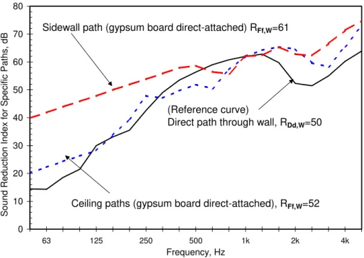
In apartments, the gypsum board ceiling is normally mounted on resilient channels (to enhance isolation from the apartment above), which reduces flanking transmission between the side-by-side units via the ceiling-ceiling path to insignificance. Flanking via an abutting side wall transmits little sound (RFf,w 61 for one wall in the case tested), but this could also
limit overall performance if the separating wall and the floor were improved, and would drop to RFf,w 58 if there were two such walls.
0 10 20 30 40 50 60 70 80 63 125 250 500 1k 2k 4k Frequency, Hz Sound Reduc tion Index for Spec ific Paths , dB
Ceiling paths (gypsum board direct-attached), RFf,W=52
(Reference curve)
Direct path through wall, RDd,W=50 Sidewall path (gypsum board direct-attached) RFf,W=61
Figure 5: Sound reduction for flanking paths not involving transmission via the wall/floor junction.
But in row housing (where transmission between stories within a dwelling unit is not a concern) the ceiling would commonly be screwed directly to the bottom of the joists. Then the ceiling-ceiling flanking path also becomes significant, as indicated in Figure 6; the associated sound transmission for this ceiling-ceiling path is given in Figure 5.
Flanking Transmission via ceiling surfaces Transmission through wall Airborne Sound Source Flanking Transmission via floor surfaces
Flanking Transmission via floor-ceiling
Flanking Transmission via ceiling surfaces Transmission through wall Airborne Sound Source Flanking Transmission via floor surfaces
Flanking Transmission via floor-ceiling
Ceiling gypsum board screwed to joists Ceiling gypsum board screwed to joists
ICSV14 • 9-12 July 2007 • Cairns • Australia
3. THE DESIGN GUIDE
Obviously, all paths should be considered for good design. In the Guide, tables present the combined effect of all paths for typical variants.
Table 1: The table gives Apparent Sound Reduction Index, R´w for “apartment design” in the case with joists perpendicular to separating walls as shown in the drawing to the right (case b in Figure 1). R´w in a given building will not exactly match the tabulated values, but the trends should apply.
Separating wall Basic Wall (Rw 52) Better Wall (Rw 57) Sidewall gypsum board Direct or
resilient Direct Resilient Floor Surface Apparent sound reduction, R´w
No topping (basic) 43 43 44 19 mm OSB stapled to subfloor 48 49 50 25 mm gypsum concrete bonded to subfloor 49 51 51 38 mm gypsum concrete + resilient mat on subfloor 51 53 54
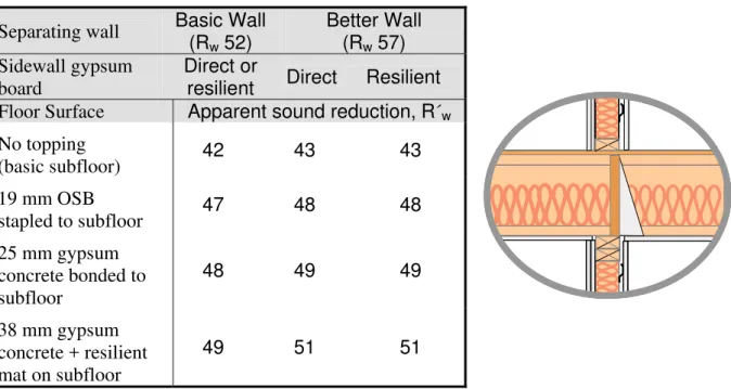
Table 2: The table gives Apparent Sound Reduction Index, R´w for “row house design” in the case with joists perpendicular to separating walls as shown in the drawing to the right – a variant on case (b) in Figure 1. Note the R´w values are significantly lower than corresponding values in Table 1 due to the stronger transmission via the ceiling-ceiling path.
Separating wall Basic Wall (Rw 52) Better Wall (Rw 57) Sidewall gypsum board Direct or
resilient Direct Resilient Floor Surface Apparent sound reduction, R´w
No topping (basic subfloor) 42 43 43 19 mm OSB stapled to subfloor 47 48 48 25 mm gypsum concrete bonded to subfloor 48 49 49 38 mm gypsum concrete + resilient mat on subfloor 49 51 51
In all cases, the overall Apparent Sound Reduction Index, R´w is lower than the Rw for
the separating wall – in some cases it is much lower. By altering design details to balance transmission via specific paths a cost-effective yet satisfactory design can be chosen.
ICSV14 • 9-12 July 2007 • Cairns • Australia
6. SUMMARY
This paper provides a very terse overview of how experimental characterization of the direct and flanking sound transmission paths in wood-framed construction can lead to a manageable set of path transmission terms to represent the effect of specific design tradeoffs. By combining the energy transmitted via all paths it is possible to arrive at estimates of the overall apparent sound reduction, R´w for a range of constructions.
We wish to acknowledge the support of our industry partners: CMHC, Forintek Canada, Marriott International, Owens Corning, Trus Joist, and USG.
REFERENCES
[1] J.D. Quirt, T.R.T Nightingale, and F. King, Guide for Sound Insulation in Wood Frame
Construction, RR-219, NRC-IRC, Canada, (2006)
[2] T.R.T. Nightingale, J.D. Quirt, F. King, R.E. Halliwell, Flanking Transmission in
Multifamily Dwellings: Phase IV, RR-218, NRC-IRC, Canada, (2006)
[3] J.D. Quirt, T.R.T. Nightingale, R.E. Halliwell, Estimates of flanking paths involving the
wall-floor junction in wood framed construction and included references, Proceedings